

Page 1
9400T Back Up Sensor
Congratulations on your purchase of the 9400T
back up sensor, designed to aid operation when
going in reverse. Easy installation and simple to
operate, the 9400T back up sensor is notifies the
driver with a series of beeps when the rear of the
vehicle comes close to anything.
Before using the 9400T back up sensor, be sure to
practice and test the product in order to familiar-
ize yourself with the beep indicators and
detection zones as they vary by vehicle.
Tools Required
■ Tape measure
■ 7/8” hole saw
■ 1/16” drill bit
■ Wire stripper
■ Electrical tape
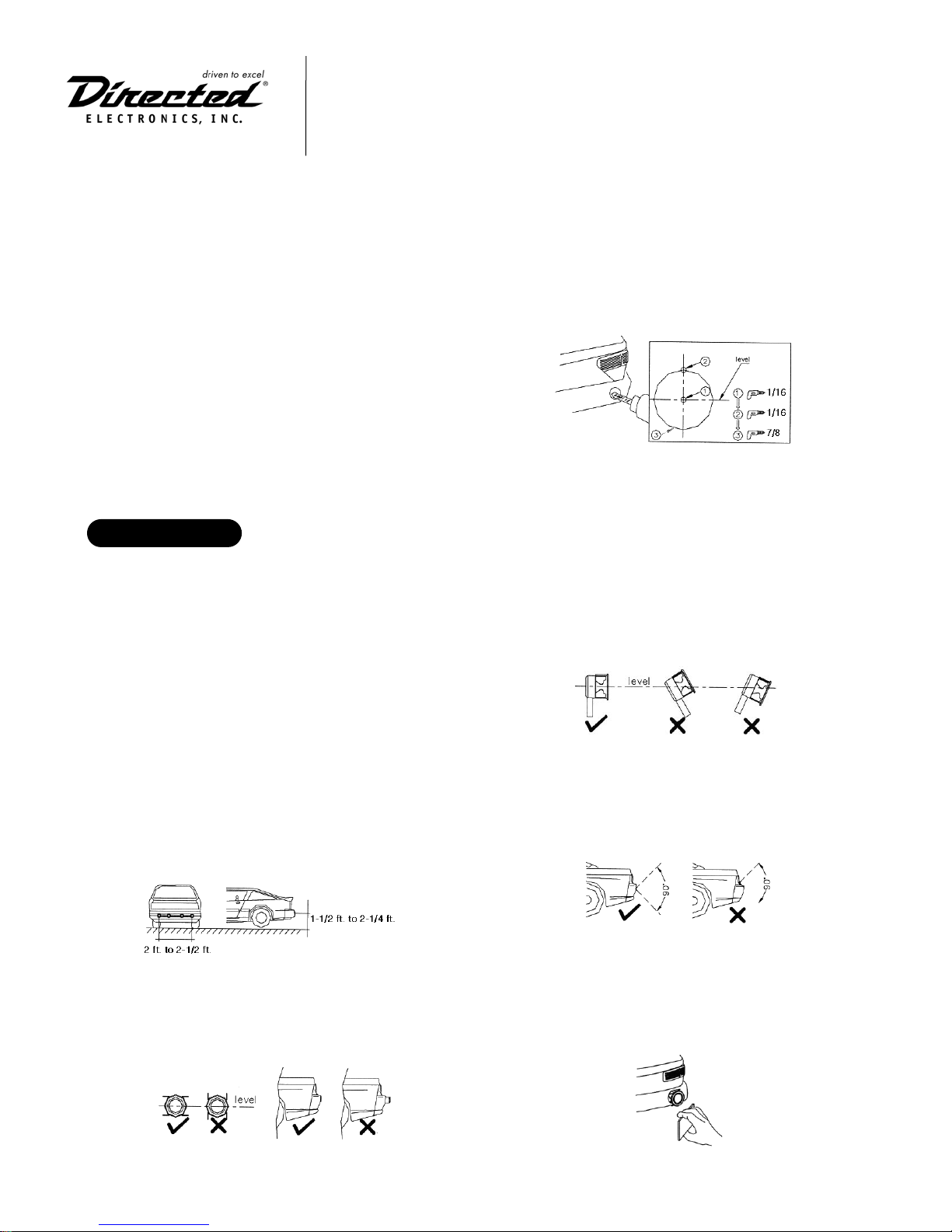
Installation
Install the sensor between 1.5 ft. and 2.25 ft.
above the ground level for optimum performance
and mount on the outer edges of the vehicle’s rear.
NOTE: Mounting the sensors on the rear tip of the vehicle
is NOT recommended as the sensors may get damaged if
rear ended.
To mount the sensors, mark four equally-spaced
points with the two outer sensors no more than 2.5
ft. apart. See the diagram below for hole sizes.
NOTE: Be sure to check the behind the drill area for
obstructions or reinforcements bars.
It is important not drill the hole larger than the
measurement indicated.
Installation Tips
The sensor should be mounted vertically and
level; mounting on a tilt or unleveled surface will
affect sensor performance.
To avoid false warnings from the sensor be sure
there are no obstructions within a 90 degree
lateral range.
After routing and attaching the cables, use a
small block of wood to press the sensors into
place.
Sensor Installation
© 2003 Directed Electronics, Inc.
N9400T 3/03
Page 2
© 2003 Directed Electronics, Inc.
N9400T 3/03
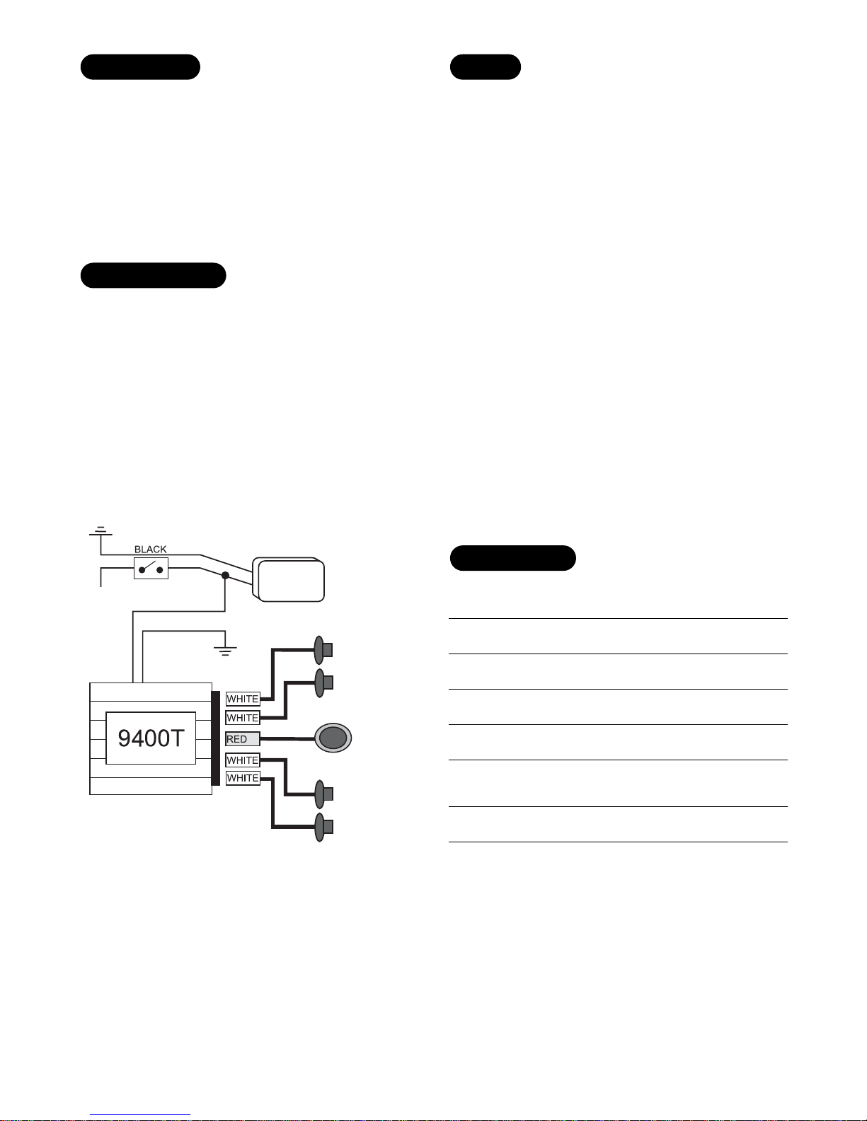
The buzzer should be mounted in an area inside the
vehicle where it can be heard clearly by the driver.
The control module should be located in the trunk
area securely mounted away from any moving parts
and in an area free of moisture and heat
■ RED Wire - Connected to the wire that
provides (+)12V when the vehicle’s
reverse light is on.
■ BLACK Wire - Connected to ground.
■ RED Connector - The buzzer is plugged
into this port.
■ WHITE Connectors - The sensors are
plugged into these ports.
NOTE: To avoid incident during testing, a second person
should watch the rear of the vehicle.
Place the gearshift in reverse. The buzzer will
emit two quick beeps indicating the system is on.
Back up the vehicle slowly.
The first beep pattern indicates the vehicle is 5 ft.
to 5.5 ft. away from the nearest obstacle. As the
vehicle gets closer to the object, the buzzer emits
a different beep patterns. Please refer to the
Detection Range chart for pattern description.
Be aware that certain shapes will mislead the
sensor and it is necessary to test the sensor
backing up against multiple shaped objects.
Objects with a rounded smooth surface may
mislead the reflecting signal.
Detecting
Stage Distance Buzzer Sound
1 5.5 ft. to 5 ft. Two Beeps
2 5 ft. to 3.25 ft. Three Beeps
3 3.25 ft. to 2.25 ft. Four beeps
4 2.25 ft. to 1.5ft. Five beeps
5 1.5 ft. to 1 ft. Three beeps then
four quick beeps
6 1 ft. to 0 ft. One long beep
NOTE: Stop the vehicle when the buzzer makes a constant
sound.
Detection Range
Testing
Wiring Instructions
Warning Buzzer
(+)12V
RED
BLACK
REVERSE
LIGHT
SENSOR 4
SENSOR 3
4
3
BUZZER
2
1
SENSOR 2
SENSOR 1
 Loading...