

Page 1
© 2005 Directed Electronics, Inc. Vista, CA
N556L 05-05
11
556L General Motors
Passlock Interface Module
The 556L General Motors Passlock Interface Module is used when
installing remote start products in GM vehicles equipped with
Passlock I and Passlock II anti-theft systems. The 556L provides
easy interfacing while maintaining the integrity of the vehicle’s
anti-theft system. The 556L interfaces with the Passlock systems
by providing the proper Resistance Code (R-Code) at the appropri-
ate time. The 556L will also provide, when necessary, a negative
signal to the bulb check wire. The 556L has no effect on the
Passlock system when the remote start is not in use. The factory
Passlock anti-theft system will remain fully functional.
IIMMPPOORRTTAANNTT!!
Before beginning the installation, make
sure that you are connecting to the correct type of
Passlock system (either Passlock I,Passlock II or alternate). You can determine which type of system is being
used by referencing the
Vehicle Application Guide
section in this manual.
The GM Passlock System is a key-based, fuel shutdown, anti-theft
system. The Passlock system requires that the key cylinder be
mechanically turned using a key. When the key cylinder is properly
turned, it generates the R-Code, which is sent to the Instrument
Panel Cluster (IPC) in Passlock I systems or the Body Control
Module (BCM) in Passlock II systems. The IPC and the BCM both
house the Passlock decoder, which then interprets the signal.
Unlike the Passkey system, Passlock must detect the correct R-Code
at the correct time. The Passlock I system uses a bulb check wire
to activate the IPC module. This wire is not present in the Passlock
II system. In the Passlock I system, the bulb check wire is
switched to ground when the ignition switch is turned to the crank
position. This initiates a time window during which the IPC ana-
lyzes the R-Code. If the R-Code is valid and received in the proper
window of time, the IPC sends a code via data bus to the
Powertrain Control Module (PCM) to enable the fuel system. The
vehicle will then start and stay running. If the R-Code is incorrect,
the vehicle will start and run for a moment and then shut off.
Passlock II also uses an R-Code, but rather than going through the
IPC, the signal is sent directly to the BCM. The Passlock decoder,
built into the BCM, then interprets the signal.
IIMMPPOORRTTAANNTT!!
See instructions for passlock system that
applies for harness 2.
IIMMPPOORRTTAANNTT!!
Do not attempt to use the 556L before
learning the Resistance Code. (See
Learning the
Resistance Code
section of this manual.)
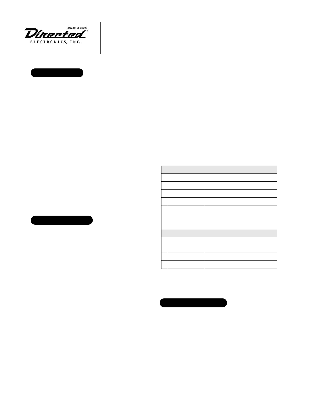
PPaasssslloocckk II WWiirriinngg DDiiaaggrraamm
HHaarrnneessss 11
1 GREEN/BLACK (+) Starter (from vehicle)
2 BLACK/WHITE Bulb check
3 BLACK Passlock ground input
4 PINK (+) Ignition (from vehicle)
5 BLUE (-) Status (from remote start system)
6 VIOLET (-) Starter (from remote start system)
7 RED (+) 12V (+ battery)
HHaarrnneessss 22
1 WHITE R-code
2 YELLOW R-code
3 WHITE/YELLOW R-code in
4 BLACK/YELLOW R-code BCM
PPaasssslloocckk SSyysstteemm DDeettaaiillss
PPrroodduucctt DDeessccrriippttiioonn
Page 2
22
© 2005 Directed Electronics, Inc. Vista, CA
N556L 05-05
GGRREEEENN//BBLLAACCKK::
Not used for this application.
BBLLAACCKK//WWHHIITTEE ((--)) oouuttppuutt ttoo bbuullbb cchheecckk wwiirree::
Connect this wire to
the 20-gauge BLACK bulb check wire in the ignition switch power
harness. This wire will test (-) ground only when the ignition
switch is turned to the crank position. Do not connect to the black
wire in the three-wire Passlock cable.
BBLLAACCKK ((--)) PPaasssslloocckk ggrroouunndd iinnppuutt::
Connect this input to the
Passlock system’s ground reference wire.
PPIINNKK ((++)) iiggnniittiioonn iinnppuutt::
Connect this wire to the heavy gauge pos-
itive (+) PINK wire of the vehicle’s main ignition.
BBLLUUEE ((--)) ssttaattuuss iinnppuutt::
Connect this wire to the (-) status output
(BLUE/WHITE or BLUE) of the Directed remote start system.
VVIIOOLLEETT ((--)) iinnppuutt ffrroomm ssttaarrtteerr rreellaayy::
Connect this wire to the (-)
starter output of the remote start system. This is the VIOLET ribbon
harness wire of the pre-wired relay pack. To verify the correct wire,
test using a digital multimeter and verify that (-) chassis ground is
present on this wire while the remote start system is engaging the
starter motor.
RREEDD ((++)) 1122 vvoolltt iinnppuutt::
Connect this wire to a source of constant
12 volts. This wire has a 5-amp fuse.
WWHHIITTEE::
Not used for this application.
YYEELLLLOOWW RR--CCooddee,, iiggnniittiioonn sswwiittcchh::
Connect this wire to the ignition
switch side of the resistance wire in the three-wire Passlock cable
in the vehicle.
WWHHIITTEE//YYEELLLLOOWW::
Not used for this application.
BBLLAACCKK//YYEELLLLOOWW RR--CCooddee,, oouuttppuutt tto
o vveehhiiccllee ssiiddee::
Connect this wire
to the side of the resistance wire facing away from the ignition
switch. This wire is located in the vehicle's three-wire Passlock
harness.
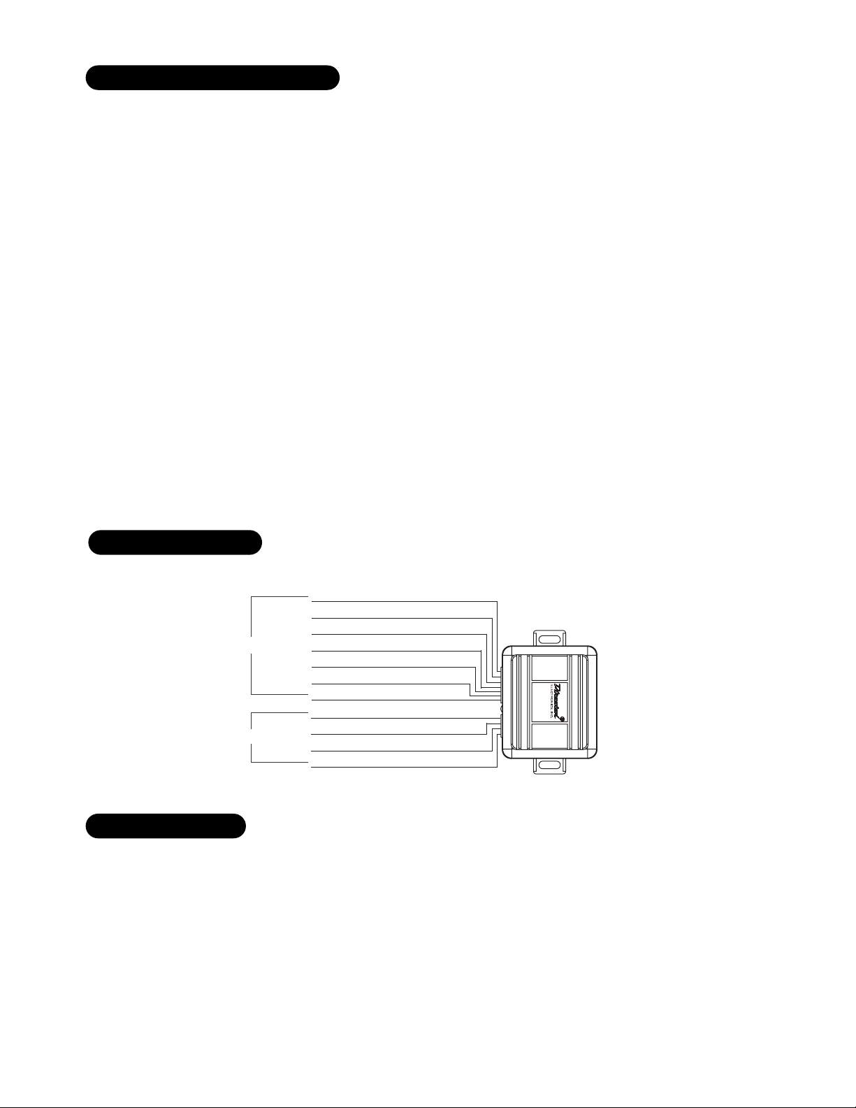
WWiirree CCoonnnneeccttiioonn GGuuiiddee ffoorr PPaasssslloocckk II
PPaasssslloocckk II WWiirriinngg DDiiaaggrraamm
The module must first be programmed before operation, use the
following procedure:
IIMMPPOORRTTAANNTT!!
The vehicle must be started within 15
seconds or the module will automatically exit the learn
routine.
1. Cycle the ignition On/Off 2 times.
2. Start the vehicle and keep it running for at least 10-seconds.
3. The LED on the module will flash 2-times.
4. Wait for the LED to flash once very quickly (within 5-seconds)
of ignition On. The R-code is learned.
3. Programming is now complete. Turn the vehicle’s ignition off
and test remote start at least twice.
NNOOTT EE ::
Refer to the end of this document for
troubleshooting procedures.
10.
Programming is now complete. Reconnect starter wire.
Test remote start at least twice.
PPaasssslloocckk II PPrrooggrraammmmiinngg
GREEN/BLACK—(not used)
BLACK/WHITE—(-) bulb check
BLACK—Passlock ground
HARNESS 1
HARNESS 2
PINK—(+) ignition
BLUE—(-) status input
VIOLET—(-) crank input
RED—(+) 12V
WHITE—(not used)
YELLOW—key side resistance in
WHITE/YELLOW—(not used)
BLACK/YELLOW—vehicle side resistance out
.
Page 3
© 2005 Directed Electronics, Inc. Vista, CA
N556L 05-05
33
GGRREEEENN//BBLLAACCKK::
Not used for this application.
BBLLAACCKK//WWHHIITTEE::
Not used for this application.
BBLLAACCKK ((--)) PPaasssslloocckk ggrroouunndd iinnppuutt::
Connect this input to the
Passlock system’s ground reference wire.
PPIINNKK ((++)) iiggnniittiioonn iinnppuutt::
Connect this wire to the heavy gauge pos-
itive (+) PINK wire of the vehicle’s main ignition.
BBLLUUEE ((--)) ssttaattuuss iinnppuutt::
Connect this wire to the (-) status output
(BLUE/WHITE or BLUE) of the Directed remote start system.
VVIIOOLLEETT ((--))::
Not used for this application.
RREEDD ((++)) 1122 vvoolltt iinnppuutt::
Connect this wire to a fused source of con-
stant 12 volts.
WWHHIITTEE::
Not used for this application.
YYEELLLLOOWW RR--CCooddee,, iiggnniittiioonn sswwiittcchh::
Connect this wire to the ignition
switch side of the Passlock II system’s cut resistance wire.
WWHHIITTE
E//YYEELLLLOOWW::
No connection.
BBLLAACCKK//YYEELLLLOOWW RR--CCooddee,, oouuttppuutt ttoo vveehhiiccllee ssiiddee::
Connect this wire
to the side of the resistance wire facing away from the ignition
switch.
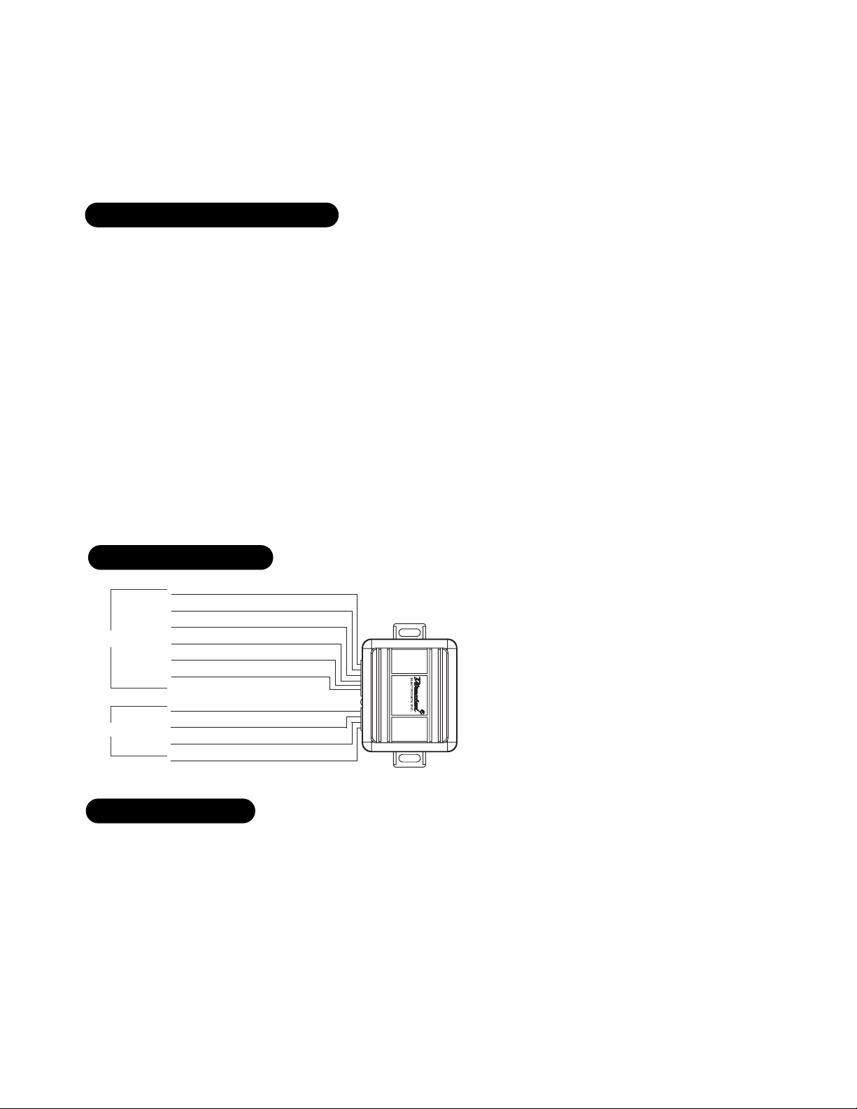
WWiirree CCoonnnneeccttiioonn GGuuiiddee ffoorr PPaasssslloocckk IIII
PPaasssslloocckk IIII WWiirriinngg DDiiaaggrraamm
The module must first be programmed before operation, use the
following procedure:
IIMMPPOORRTTAANNTT!!
The vehicle must be started within 15
seconds or the module will automatically exit the learn
routine.
1. Cycle the ignition On/Off 2 times.
2. Start the vehicle and keep it running for at least 10-seconds.
3. The LED on the module will flash 2-times.
4. Wait for the LED to flash once very quickly (within 5-seconds)
of ignition On. The R-code is learned.
3. Programming is now complete. Turn the vehicle’s ignition off
and test remote start at least twice.
NNOOTT EE ::
Refer to the end of this document for
troubleshooting procedures.
PPaasssslloocckk IIII PPrrooggrraammmmiinngg
NNOOTT EE ::
Refer to the end of this document for
troubleshooting procedures.
GREEN/BLACK—(not used)
BLACK/WHITE—(not used)
BLACK—Passlock ground
HARNESS 1
HARNESS 2
PINK—(+) ignition input
BLUE—(-) status input
VIOLET—(not used)
RED—(+) 12V
WHITE—(not used)
YELLOW—key side resistance in
WHITE/YELLOW—(not used)
BLACK/YELLOW—vehicle side resistance out
.
Page 4

44
© 2005 Directed Electronics, Inc. Vista, CA
N556L 05-05
CCAANNYYOONN//CCOOLLOORRAADDOO WWiirriinngg DDiiaaggrraamm
GGRREEEENN//BBLLAACCKK::
(+) starter wire.
BBLLAACCKK//WWHHIITTEE::
Not used for this application.
BBLLAACCKK ((--)) PPaasssslloocckk ggrroouunndd iinnppuutt::
This wire must be connect to a
good chassis ground.
PPIINNKK ((++)) iiggnniittiioonn iinnppuutt::
Connect this wire to the heavy gauge pos-
itive (+) PINK wire of the vehicle’s main ignition.
BBLLUUEE ((--)) s
sttaattuuss iinnppuutt::
Connect this wire to the (-) status output
(BLUE/WHITE or BLUE) of the Directed remote start system.
VVIIOOLLEETT ((--))::
Not used for this application.
RREEDD ((++)) 1122 vvoolltt iinnppuutt::
Connect this wire to a source of constant
12 volts. This wire has a 5-amp fuse.
WWHHIITTEE RR--CCooddee,, kkeeyy ssiiddee::
Connect this wire to the ignition switch
side of the Passlock system’s cut resistance wire..
YYEELLLLOOWW::
Not used for this application.
WWHHIITTEE//YYEELLLLOOW
W::
Connect to the uncut reference resistance in wire
of the ignition switch.
BBLLAACCKK//YYEELLLLOOWW RR--CCooddee,, oouuttppuutt ttoo vveehhiiccllee ssiiddee::
Connect this wire
to the side of the resistance wire facing away from the ignition
switch.
WWiirree CCoonnnneeccttiioonn GGuuiiddee ffoorr
CCaannyyoonn//CCoolloorraaddoo IInntteerrffaaccee
CCAANNYYOONN//CCOOLLOORRAADDOO WWiirriinngg IInntteerrffaaccee
GREEN/BLACK—(+) starter wire
BLACK/WHITE—(not used)
BLACK—chassis ground
HARNESS 1
HARNESS 2
PINK—(+) ignition input
BLUE—(-) status input
VIOLET—(not used)
RED—(+) 12V
WHITE—keyside resistance in
YELLOW—(not used)
WHITE/YELLOW—uncut wire + reference
BLACK/YELLOW—vehicle side resistance out
.
KEY
CYLINDER
WHITE/YELLOW (556L)
WHITE/YELLOW
or
WHITE/BLACK
BCM
CUT
WHITE (556L)
BLACK/YELLOW (556L)
WHITE/BLUE
or
WHITE
Page 5

© 2005 Directed Electronics, Inc. Vista, CA
N556L 05-05
55
The module must be programmed before first operation, use the
following procedure:
IIMMPPOORRTTAANNTT!!
The vehicle must be started within 15
seconds or the module will automatically exit the learn
routine.
1. Cycle the ignition On/Off four times (1/2 to 1 second).
2. On the 5
th
time crank the engine and hold in that position.
3. There will be a series of 4 flashes, continue to hold in the
crank position for 10-20 seconds until a 5
th
quick flash is
obtained.
4. The R code is now learned, turn the engine off and remove the
ignition key.
5. Programming is now complete. Test the remote start at least
twice.
CCAANNYYOONN//CCOOLLOORRAADDOO PPrrooggrraammmmiinngg
Refer to vehicle specific information on DirectWire or refer to doc-
ument 1059.
VVeehhiiccllee AApppplliiccaattiioonn GGuuiiddee
Page 6

66
© 2005 Directed Electronics, Inc. Vista, CA
N556L 05-05
If the vehicle remote starts and then quickly dies, follow the below
steps in order to resolve the problem.
1. Shut down the remote start
2. Is the Theft System light flashing or off? If the light is off
advance to step 3. If the light is flashing advance to step 4.
3. Start the vehicle with the key.
■ If the vehicle starts make sure the BLACK wire on the
556L is soldered to the center BLACK wire of the vehicle
passlock wires, also verify that the bulb check wire has
been correctly identified and is soldered to the BLACK/
WHITE wire of the 556L, Check the connection on the
VIOLET wire of the 556L to the relay satellite ribbon
harness VIOLET wire, both of these wires are required for
passlock 1.
■ If the vehicle does not start and the Theft System light
remains solid, recheck all connections and meter the
passlock wires to verify you have interfaced with the
correct wires.
4. Wait five seconds and attempt to restart the vehicle with the
key. If the vehicle will not start with the key advance to step 5.
If the vehicle starts and stays running, recheck all connec-
tions. The vehicle has entered Short Tamper mode caused by
a failure of the passlock module to read the R-code within the
time window allowed, verify that the blue/black off the 556L
is seeing a ground trigger when remote started, and is sol-
dered to the Blue status output from the remote start unit. If
3 attempts are made to start the vehicle in which no R-code
is read the passlock system will enter Long Tamper mode
5. The system has entered Long Tamper mode, this mode will not
allow the vehicle to start for 10 minutes, long tamper mode
is almost always caused by the wrong R-code being sent to
the passlock module. This will immediately cause a No-Start
condition, even if an attempt is made to start the vehicle
with the key, In this case wait 10 minutes and reattempt to
learn the R-code after all connections have been verified.
If the vehicle remote starts and then quickly dies, follow the below
steps in order to resolve the problem.
1. Shut down the remote start.
2. Is the Theft System light flashing or off? If the light is off
advance to step 3. If the light is flashing advance to step 4.
3. Start the vehicle with the key.
■ If the vehicle starts, use a meter to confirm that the
correct wires have been interfaced. Verify all connec-
tions and make sure the BLACK wire on the 555L is
soldered to the ORANGE/BLACK or BLACK wire of the
vehicle passlock wires. Then verify that the VIOLET and
BLACK/WHITE wires from the 555L are NOT connected to
anything, the YELLOW goes to the key cylinder side of
the yellow passlock wire, and the BLACK/YELLOW goes to
the car side of the YELLOW passlock wire.
■ If the vehicle does not start with the key advance to
step 4.
4. Wait five seconds, then attempt to start the vehicle with the
key.
■ If the vehicle will not start with the key advance to step
5.
■ If the vehicle starts and stays running, recheck all con-
nections. The vehicle has entered the Short Tamper
mode. This is caused by a failure of the passlock module
to read the R-code within the time window allowed.
Verify that the BLUE/BLACK wire off the 555L is seeing
a ground trigger when remote started and is soldered to
the BLUE status output from the remote start unit. If
three attempts are made to start the vehicle in which no
R-code is read the passlock system will enter Long
Tamper mode.
5. The system has entered Long Tamper mode. This will not
allow the vehicle to start for 10 minutes. Long tamper mode
is almost always caused by the wrong R-code being sent to
the passlock module. This will immediately cause a No-Start
condition, even if an attempt is made to start the vehicle
with the key. In this case wait 10 minutes and reattempt to
learn the R-code after all connections have been verified.
TTrroouubblleesshhoooottiinngg PPaasssslloocckk 22TTrroouubblleesshhoooottiinngg PPaasssslloocckk 11
Page 7

© 2005 Directed Electronics, Inc. Vista, CA
N556L 05-05
77
Page 8

© 2005 Directed Electronics, Inc. Vista, CA
N556L 05-05
 Loading...