

Page 1

Security System 3808A
Installation Guide
This product is intended for installation by a professional
installer only! Attempts to install this product by a person other than a trained professional may result in severe
damage to a vehicle’s electrical system and components.
© 2012 Directed Electronics, Vista, CA
N3808A 2012-01
Page 2
Bitwriter®, Code Hopping™, Doubleguard®, ESP™, FailSafe®, Ghost Switch™, Learn Routine™, Nite-Lite®, Nuisance Prevention® Circuitry, Revenger®, Silent Mode™,
Soft Chirp®, Stinger®, Valet®, Vehicle Recovery System®,
VRS®, and Warn Away® are all Trademarks or Registered
Trademarks of Directed Electronics.
The Bitwriter® (p/n 998U)
requires chip version 2.8 or
newer to program this unit.
Bitwriters with a date code of 6a or older require an IC upgrade (p/n
998M). Some bitwriters with a date code of 6B do not require the IC
upgrade, refer to tech tip # 1112 for more information.
Page 3

Contents
Wiring Diagram ............................................................................................................................. 5
10 Pin Main Harness ................................................................................................................. 5
4 pin Auxiliary/Pin switch Monitor Harness .................................................................................. 8
3 pin Door Lock Harness ............................................................................................................ 9
5 pin RKE (Remote Keyless Entry) Harness .................................................................................... 9
Light flash Polarity Setting ......................................................................................................... 10
Programming System Features ........................................................................................................ 11
Feature Menu ......................................................................................................................... 11
Feature Descriptions (consumer factory default settings are in bold) ............................................... 12
Remote Control Programming and Deletion ...................................................................................... 14
System Testing and Impact Sensor Adjusting ..................................................................................... 15
RF Security Setting ................................................................................................................... 15
OEM Security Setting ............................................................................................................... 16
Dealer Security ....................................................................................................................... 16
Nuisance Prevention Circuitry (NPC) ............................................................................................... 17
Long Term Event History ................................................................................................................. 17
Table of Zones .............................................................................................................................. 17
Rapid Resume Logic ...................................................................................................................... 17
Troubleshooting: Alarm .................................................................................................................. 18
Page 4

4
© 2012 Directed. All rights reserved.
Page 5
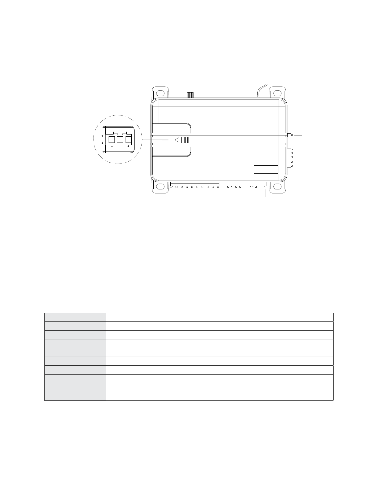
Wiring Diagram
Light Flash
Polarity Jumper Detail
LIGHT FLASH POLARITY
(10A (MAXIMUM) FUSE JUMPER)
Sensor
Adjustment
Antenna
(Red Plug)
Programmer Port
(Blue Plug)
Valet/LED Port
10 Pin Main Harness
BLACK (-) CHASSIS GROUND
RED (+) 12V CONSTANT POWER
WHITE/BLACK LIGHT FLASH RELAY ISOLATION WIRE (87a)
WHITE (+/-) LIGHT FLASH RELAY OUTPUT (30)
YELLOW (+) IGNITION INPUT
RED/WHITE
BROWN
ORANGE
VIOLET
GREEN (-) DOOR TRIGGER INPUT
© 2012 Directed. All rights reserved.
(-) 200 mA TRUNK POP OUTPUT
(-) 200 mA HORN/SIREN OUTPUT
(-) 500 mA GROUND WHEN ARMED OUTPUT
(+) DOOR TRIGGER INPUT
5
Page 6
This system can be configured in two different ways.
1. as an add-on security system to the vehicles factory keyless entry system.
2. as a full security system added to the vehicle.
This guide covers the installations of both configurations and is labeled respectively.
BLACK (-) CHASSIS GROUND
This wire is the main unit’s source of ground. DO NOT connect this wire to any factory ground points; they
can cause noise and/or current loss which can affect system performance. Ground the main unit and any
accessories to the same point in the vehicle, (preferably the kick panel). Scrape away any paint and use a
factory bolt or make your own ground with a self-tapping screw and a star washer
[Required connection for both configurations]
RED (+) 12V CONSTANT INPUT
This wire supplies power to the main units’ micro-controller. Remove the supplied fuse before connecting to
the positive terminal of the battery or a constant +12V supply to the ignition switch.
Note: Always use a fuse within 12 inches of the point you obtain (+)12V. Do not use the 15A fuse in the
harness for this purpose. This fuse protects the module.
[Required connection for both configurations]
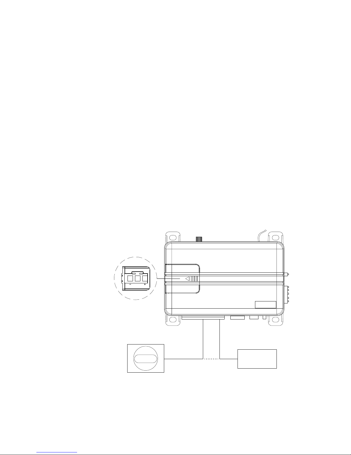
WHITE/BLACK LIGHT FLASH ISOLATION WIRE (PIN 87a of onboard relay)
This wire is a parking light flash input from the vehicle light switch that connects to pin 87a of the on-board
light flash relay. It is used for vehicles requiring light switch isolation during light flash output. For vehicles
with multiplex light circuits that require switch isolation, the on-board light flash fuse can be replaced with
the specified resistor value (paying attention to the circuit polarity). See diagram below for wiring information.
Note: Replace fuse with specied resistor value
if connecting to multiplex light circuit
(paying special attention to polarity selection).
Light Flash
Polarity Jumper Detail
LIGHT FLASH POLARITY
(10A (MAXIMUM) FUSEJ UMPER)
Light Switch
WHITE/BLACK
Multiplex wire
in vehicle
[Vehicle specific optional connection both configurations]
Cut
X X
WHITE
To control module
in vehicle
6
© 2012 Directed. All rights reserved.
Page 7

WHITE PARKING LIGHT OUTPUT
This wire should be connected to the parking light wire in the vehicle. See setting the light flash polarity section of this guide for polarity settings.
Note: For parking light circuits that draw 10 amps or more, the internal jumper must be switched to a (-)
light flash output. (See setting the light flash polarity section of this guide.) P/N 8617 or a standard automotive SPDT relay must be used on the light flash output wire.
[Required connection for both configurations]
YELLOW (+) IGNITION INPUT
Connect this wire to the (+)12V ignition wire. This wire must show (+)12V with the key in Run position and
during cranking. Take care to insure that this wire cannot be shorted to the vehicle chassis at any point.
[Required connection for both configurations]
RED/WHITE (-) 200mA TRUNK RELEASE OUTPUT
When the system receives the code controlling trunk release, for longer than 1.5 seconds, the RED/WHITE
wire will supply an output as long as the transmission continues (up to 25 seconds max). This is often used
to operate a trunk/hatch release or other relay-driven function.
Important! This output is only intended to drive a relay. It cannot be connected directly to a high current
device
[Optional connection for both configurations]
BROWN (-) 200mA HORN OUTPUT
This wire supplies a (-) 200 mA output that can be used to honk the vehicle horn or it can be connected to
the (-) input of an optional siren.. It outputs a single pulse when locking the doors with the remote, and two
pulses when unlocking with the remote. This wire also outputs pulses for 30 seconds when Panic Mode is
activated. If the vehicle has a (+) horn circuit P/N 8617 or a standard automotive SPDT relay must be used
on the horn output wire.
NOTE: This wire can be programmed as a siren output see features programming.
[Required connection for both configurations]
ORANGE (-) 500mA GROUND WHEN ARMED OUTPUT
This wire supplies a (-) 500 mA ground as long as the system is armed. This output ceases as soon as the
system is disarmed. The GWA can be hooked up to an optional starter kill relay, a voice module or any accessory that requires a ground when armed.
NOTE: If an optional remote start is added to the system, this wire will act as an anti-grind output.
[Optional connection for both configurations]
VIOLET (+) DOOR TRIGGER INPUT
This wire is used in vehicles that have a positive (+) switched dome light circuit. Connect the violet wire to a
wire that shows (+) 12V when any door is opened, and ground when the door is closed. [Required connection for both configurations but not required if the vehicle has a (-) door trigger circuit]
GREEN (-) DOOR TRIGGER INPUT
This wire is used in vehicles that have a negative (-) switched dome light circuit. Connect the green wire to a
wire that shows (-) when any door is opened, and (+)12V when the door is closed. [Required connection for
both configurations but not required if the vehicle has a (+) door trigger circuit]
© 2012 Directed. All rights reserved.
7
Page 8

4 pin Auxiliary/Pin switch Monitor Harness
Trunk Pin Input
Flex Output (-) Activation Input
(-) Status Output
Ignition Input Ignition Output
ALARM MODULE
REMOTE START
MODULE
To Trunk pin in
vehicle (if used)
BLACK/WHITE (-) 200 mA FLEX 2 OUTPUT (DOME LIGHT SUPERVISION)
BLUE/BLACK (-) 200 mA FLEX 1 OUTPUT (2nd UNLOCK)
GRAY (N/O or N/C) HOOD TRIGGER INPUT
BLUE (-) TRUNK/MUX TRIGGER INPUT
BLACK/WHITE (-) 200mA FLEX 2 OUTPUT
From factory this output is used for a dome light supervision relay, this output can be programmed for other
functions (see features programming table/descriptions for options and how to activate with an add-on
security system).
Important! This output is only intended to drive a relay. It cannot be connected directly to a high current
device.
[Optional connection for both configurations]
BLUE/BLACK (-) 200mA FLEX 1 OUTPUT
From factory this output is used for optional progressive unlock, A progressive unlock system unlocks the
driver’s door when the unlock button is pressed and unlocks the passenger doors if the unlock button is
pressed again within 15 seconds after unlocking the driver’s door. This output can be programmed for other
functions (see features programming table/descriptions for options and how to activate with an add-on
security system).
Important! This output is only intended to drive a relay. It cannot be connected directly to a high current
device.
[Optional connection for both configurations]
GRAY (N/O or N/C) HOOD TRIGGER INPUT
Connect to a wire that changes state when the hood is opened. N/O = rests at ground when the hood is
OPEN, N/C= rests at ground when the hood is CLOSED (see features programming table for options).
[Optional connection for both configurations]
BLUE (-) TRUNK/MUX TRIGGER INPUT
Connect to a wire that goes to ground (-) when the trunk is opened or to the pre-trigger and full trigger
outputs of an optional Directed Electronics dual zone sensor. This wire is also used for sensor shunt when
adding an optional remote start. See diagram below for sensor shunt wiring information.
[Optional connection for both configurations]
8
© 2012 Directed. All rights reserved.
Page 9

3 pin Door Lock Harness
GRAY/BLACK (+)
Shunt Input
(+) Trunk Release
Motor Wire
BLUE (-)
Trunk Pin Input
ALARM MODULE
To Trunk Pin
To BCM/Control Relay
Trunk Release
Solenoid
GREEN (-) 200mA LOCK OUTPUT
EMPTY NOT USED
BLUE (-) 200mA UNLOCK OUTPUT
GREEN (-) LOCK OUTPUT
Connect to a wire that pulses ground to activate the vehicle door lock relay. (Usually at the door lock switch
or BCM).
[Optional connection for both configurations]
BLUE (-) UNLOCK OUTPUT
Connect to a wire that pulses ground to activate the vehicle door unlock relay. (Usually at the door unlock
switch or BCM).
[Optional connection for both configurations]
NOTE: For door lock wiring diagrams refer to document #1041 under the Resources tab at www.directechs.com
5 pin RKE (Remote Keyless Entry) Harness
GRAY/BLACK (+) OEM TRUNK SHUNT INPUT
RED/BLACK (+/-) DISARM DEFEAT INPUT
RED (+) DISARM INPUT
GREEN/BLACK (+/-) ARM DEFEAT INPUT
DARK GREEN (+) ARM INPUT
GRAY/BLACK (+) TRUNK SHUNT INPUT
Connect to a wire that pulses (+)12V when the OEM trunk release is activated. If the system is armed when
the trunk is opened with the OEM remote, the shock sensor and trunk trigger will be bypassed until the trunk
is closed. See diagram below for sensor shunt wiring information.
NOTE: The blue (-) trunk pin input must be connected for feature to work correctly.
[Optional add-on security connection]
© 2012 Directed. All rights reserved.
9
Page 10

RED/BLACK (+/-) DISARM DEFEAT INPUT
Connect to a wire that pulses (+) 12V OR ground when ALL doors unlock (usually the passenger door motor
or driver door unlock switch). Disarming will be defeated if this wire receives a pulse simultaneously with
the Disarm input. This is a polarity selectable input, (see features programming table for options).
[Required add-on security system connection]
RED (+) DISARM INPUT
Connect to a wire (usually the driver door motor) that pulses (+) 12V when the driver door unlocks using the
OEM remote to disarm the system. This wire triggers the Disarm command for the system.
[Required add-on security connection]
GREEN/BLACK (+/-) ARM DEFEAT INPUT
Connect to a wire that pulses (+) 12V OR ground when the doors lock (usually the driver door lock switch).
Arming will be defeated if this wire receives a pulse simultaneously with the Arm input. This is a polarity
selectable input, (see features programming table for options).
[Optional add-on security connection]
DARK GREEN (+) ARM INPUT
Connect to a wire (usually the driver door motor) that pulses (+) 12V when the doors lock. This wire triggers
the Arm command for the system.
[Required add-on security connection]
Light flash Polarity Setting
The internal fuse is used to determine the light flash output. In the (+) position, the on-board relay outputs (+)
12V on the WHITE wire. In the (-) position, the on-board relay will supply a (-) output. When wiring into a
multiplex circuit, you can replace the fuse with a resistor (paying attention to the polarity setting). (Refer to
diagram on White/ Black wire description).
Note: For parking light circuits that draw 10-amps or more, the internal jumper must be switched to a (-)
light flash output. P/N 8617 or a standard automotive SPDT relay must be used on the light flash output
wire.
Light Flash
Polarity Jumper Detail
Note: Replace fuse with specied resistor value
if connecting to multiplex light circuit
(paying special attention to polarity selection).
LIGHT FLASH POLARITY
(10A (MAXIMUM) FUSEJ UMPER)
[Required connection for both configurations]
10
© 2012 Directed. All rights reserved.
Page 11

Programming System Features
The System Features Learn Routine dictates how the unit operates. It is possible to access and change any of
the feature settings using the Valet button. However, this process can be simplified by using the Bitwriter.
Note : The Bitwriter requires chip version 2.8 or newer to program this unit.
To program features:
1. Open a door, turn the ignition on and then off
2. Press/release the Valet button the number of times corresponding to the menu item number and feature
you wish to change in Feature Menu table below and then press/hold
3. The horn/siren sounds and the LED flashes the specified number to confirm the selected item.
4. The button can be released (Exit in 30 seconds if no action is performed)
5. Select the option by pressing the Arm/Disarm buttons of a programmed dealer master or consumer
remote control.
• Pulsing +12V on the Arm input wire selects options when a remote has not been programmed
6. The horn/siren sounds and the LED flashes to indicate the selected option
7. To save the option and select the next menu item to program - return to Step 2 above.
8. To exit turn the ignition on, the horn/siren sounds twice to confirm.
NOTE: When installed as an Add-on Security System or an Add-on Sensor System; pressing the Lock/Unlock buttons of the OEM Remote selects options as in Step 5 above.
The learn routine Exits if any of the following occurs:
• Theopendoorisclosed
• Theignitionisturnedon
• Thereisnoactivityfor30seconds
• Thevaletbuttonispressedtoomanytimes
Feature Menu
Menu
12** Sensor Add Arming Type Active
Feature Option 1 Option 2 Option 3 Option 4 Option 5
Item
1 Security Features On*
2 Arming Type Active* Passive-no lock
3 Arm/Disarm chirps
4 Ignition control locks No ignition locks*
5 Panic On*
6 Hood Trigger type
7 Horn function Siren
8 Door trigger error chirp
9 Door lock output
10 Arm defeat polarity
11 Disarm defeat polarity
13 Flex Output 1 Domelight Supervi-
14 Flex Output 2
15 OEM Alarm Arming
On
Normally Open
(On)
(0.8sec)
(Positive)
(Positive)
sion
(Domelight Supervision)
Instant
(Off)
(Passive-lock)
(Off)*
Lock and unlock
(Off)
Normally Closed
(Horn 10 ms)
Off
3.5 sec 0.4 sec. double unlock (0.4
Negative
Negative
(Passive)
(Factory Alarm
Disarm)
Factory Alarm
Disarm
Delay
Lock only Unlock only
Horn 20 ms Horn 40 ms Horn 50 ms
sec)
2nd unlock Factory Alarm
Trigger
2nd unlock Factory Alarm
Trigger
Remote Start
Report
Remote Start
Report
**This feature does not apply to this system
© 2012 Directed. All rights reserved.
11
Page 12

Table Notes:
1. Items 1-5
• * indicates default Consumer mode options when changed to a Consumer mode of operation. Any
changes must be made after the system is set to Consumer mode.
• BOLD type indicates Dealer Security mode default settings when a Dealer Master Remote has been
programmed to the system.
2. Items 6-14
• These options are specific to the vehicle interface and remain as programmed when the system is
changed to Dealer mode or Consumer mode.
3. Quick access:
• To turn on the honk/chirp feature without entering programming; simply turn on the ignition and press
and hold the Valet button, the unit will respond with a single honk/chirp when turning the feature
ON.
• To turn off the honk/chirp feature follow the above steps, the unit will respond with a double honk/
chirp when turning the feature off.
Feature Descriptions (consumer factory default settings are in bold)
Security Features:
• On: The main unit will monitor all alarm zones and trigger as normal when activated.
• Off: Trigger zones will be ignored when armed and will not trigger if activated (convenience functions still operate as normal)
Arming Type:
• Active: the remote must be used to arm the system
• Passive Arm w/o lock: after exiting the vehicle the system will automatically arm. The doors will not
lock
• Passive Arm w/lock: after exiting the vehicle the system will automatically arm and lock the doors
Note: In consumer mode; passive arming occurs 60 seconds after the door is closed. in dealer mode;
passive arming occurs 30 seconds after after the door is closed.
Arm/Disarm Chirps:
• On: arm, disarm, and sensor warn-away chirps are active
• Off: arm and disarm chirps are defeated, warn-away chirps are active
Ignition Controlled Locks:
• No Ignition-locking: the door lock/unlock outputs will not activate when ignition is turned on/off
• Lock & Unlock: the door lock & unlock output will activate when ignition is turned on & off
• Lock Only: the door lock output will activate when ignition is turned on
• Unlock Only: the door unlock output will activate when ignition is turned off
Panic:
• On: the Panic output can be activated at any time
• Off: the Panic output is defeated
Hood Trigger Type:
• Normally Open: for vehicles with a hood switch that rests at ground when the hood is OPEN
• Normally Closed: for vehicles with a hood switch that rests at ground when the hood is CLOSED
Horn Function:
• Siren Function: The horn output will emulate the siren output when arming/disarming and will stay
on constant for panic/trigger outputs
• Horn Function 10/20/40/50ms: The horn output will pulse for the selected duration when arming/
disarming and pulse 600ms on/600ms off during panic/trigger outputs
12
© 2012 Directed. All rights reserved.
Page 13

Door Trigger Error Chirp:
• On: if the door trigger is active when arming, the horn/siren will emit an additional sound as an
alert notification
• Off: an active door trigger when arming will not create an alert output
Door Lock Output:
• 0.8 seconds: the door lock output pulses will be 800ms in duration
• 3.5 seconds: the door lock pulses will be 3.5 seconds in duration
• 0.4 seconds: the door lock pulses will be 400ms in duration
• Double Unlock (0.4 seconds): the unlock output only will pulse twice and will be 400ms in duration
Arm Defeat Polarity(for add-on security setting):
• Positive: Arm defeat wire requires a positive pulse to defeat the arm operation
• Negative: Arm defeat wire requires a negative pulse to defeat the arm operation
Note: in both options above the Ignition Override will also be functional
Disarm defeat polarity (for add-on security setting):
• Positive: Disarm defeat wire requires a positive pulse to defeat the disarm operation
• Negative: Disarm defeat wire requires a negative pulse to defeat the disarm operation
Sensor Add Arming Type (for sensor-add setting):
• Active: requires same activation input on door motor wires as RKE security to arm the sensor
• Passive: sensor arms by timer duration after the ignition is turned off and vehicle is exited.
Note: This feature does not apply to this system.
Flex Output 1:
• Dome light: The output will turn on for 30 seconds (or until the ignition is turned on) each time the
system is disarmed. If on, it will turn off if the system state changes from disarmed to armed.
• FAD (Factory Alarm Disarm): The output will pulse once for 800ms when disarming or activating
the trunk release. The disarm pulse will begin 500mS before the unlock or trunk release output
begins.
• 2nd unlock: The output will pulse for 800ms upon the 2nd Disarm command from a remote. It will
also pulse when ignition is turned off for ignition controlled unlocking; only if the user activated the
2nd unlock output prior to entering the vehicle.
• FAT (Factory alarm trigger): The output will pulse once for 800ms when the on-board shock sensor
detects a full trigger. This setting is used when adding this system to a vehicle to trigger the factory
alarm.
• Remote Start Report: The output will pulse once for 800ms when the
button on the remote is
pressed OR when pressing the LOCK button on the OEM remote twice.
NOTE: when programmed for remote start report the
panic will be controlled by pressing the
Flex Output 2:
• Dome light: The output will turn on for 30 seconds (or until the ignition is turned on) each time the
system is disarmed. If on, it will turn off if the system state changes disarmed to armed.
• FAD (Factory Alarm Disarm): The output will pulse once for 800ms when disarming or activating
the trunk release. The disarm pulse will begin 500ms before the unlock or trunk release outputs
begin.
• 2nd unlock: The output will pulse for 800ms upon the 2nd Disarm command from a remote. It will
also pulse when ignition is turned off for ignition controlled unlocking; only if the user activated the
2nd unlock output prior to entering the vehicle.
• FAT (Factory alarm trigger): The output will pulse once for 800ms when the on-board shock sensor
detects a full trigger. This setting is used when adding this system to a vehicle to trigger the factory
alarm.
• Remote Start Report: The output will pulse once for 800ms when the button on the remote is
pressed OR when pressing the LOCK button on the OEM remote twice.
NOTE: when programmed for remote start report the
panic will be controlled by pressing the
© 2012 Directed. All rights reserved.
button will no longer control the panic feature,
button on the remote for 3 seconds.
button will no longer control the panic feature,
button on the remote for 3 seconds.
13
Page 14

OEM Alarm Arming (for add-on security system setting)
AUX
AUX
• Instant: When Armed by a pulse on the Arm input, the arming operation will be same as using a
TX to arm.
• Delay: When Armed by a pulse on the Arm input, the arming operation will have a 30 second Ignition Override timer before fully arming. If the Ignition is turned on before the end of the 30 seconds
the system will disarm.
Remote Control Programming and Deletion
1. Open a door and turn the ignition on .
2. Press/release once and then press/hold the Valet button (one horn/siren sound confirms selection) or
press/release twice and then press/hold to delete remote controls (two horn/siren sounds confirms selection).
3. The button can be released (Learning exits in 30 seconds).
4. Press/hold the remote control
remote controls press the
5. The horn/siren emits one sound to confirm. If deleting the Dealer Master Remote press and hold the "insert unlock icon" button until the transmit LED turns on solid (10 seconds)
6. Repeat for each Consumer remote to be learned (up to four). For additional Dealer Master Remote controls, enter the same code of the original Dealer Master Remote that has already been programmed to
the system.
7. Turn the ignition off or wait 30 second to exit learning, the horn/siren emits 2 sounds to confirm.
Note: If consumer remotes have been programmed to the system the main unit will be placed in dealer
mode by programming a Dealer Master Remote to the system. However, if a Dealer Master remote has
been programmed, it must be deleted before the system will accept the Consumer remotes.
button until the transmit LED turns on solid (10 seconds) or if deleting all
button of a programmed remote.
Menu Table:
Item Function
1 sound/flash Auto learn new remote
2 sounds/flashes Delete all remote controls
Basic Remote Functions Table
Press and Release
Button
Arm Silent Arm Arm and Panic
Disarm Silent Disarm No Function
Shift and Sensor
Bypass
Optional Remote
Starter
Shift (Press/
release “AUX”
first)
No Function Trunk release
Car Finder Panic on
NOTE: See Owner/Dealer Master Remote Guide for more details
Press/Hold
for 2 secs.
on
14
© 2012 Directed. All rights reserved.
Page 15

System Testing and Impact Sensor Adjusting
RF Security Setting
Arming
1. Press the
2. Doors lock, Lights flash and the horn/siren sounds once
• For silent arming; press the AUX button prior to pressing the
3. Dome light turns off, starter kill becomes active, and the status LED begins flashing.
4. While arming, the system tests the trigger inputs for status. If any trigger inputs are active when arming
the horn/siren sounds a second time as a notification, both the onboard impact sensor and the active
input are bypassed. The open zone is bypassed until corrected and the impact sensor is bypassed for
a maximum of 4 minutes. While bypassed, the active input is indicated by the status LED flashes (see
table of zones for LED flashes).
5. Sensor testing:
a. Gently impact the vehicle with increasing intensity to test the pre-trigger level (10 horn/siren sounds.
b. Impact that location more heavily to test the full-trigger level (horn/siren/lights for 30 sec.)
c. Adjust the sensor pot until the desired levels are obtained
Note: The Nuisance Prevention feature bypasses the sensor after three full-triggers; to reset if active,
disarm the system and turn the ignition on/off.
6. Protected entry tests:
• Open each door, the horn/siren sounds quickly and then begin the full-trigger output
• Open the hood or trunk, or turn on the ignition to immediately begin the full-trigger output.
Note: The Nuisance Prevention feature bypasses an input that stays active for three full-triggers; close the
input to reset.
Sensor Bypass
1. Press and release the AUX button within 5 seconds after
pre-trigger output is bypassed
2. Press and release the AUX button again within 5 seconds, the lights flash three times and the pre-trigger and full-trigger outputs are bypassed
3. Press the
button on the remote
button.
button, the lights flash two times and the
button anytime to reset the sensor
Disarming
1. Press the
2. Doors unlock, Lights flash and the horn/siren sounds two times. If the system has been triggered, the
horn/siren sounds four times or five times if the sensor is bypassed
• For silent disarming; press the AUX button prior to pressing the
3. Dome light turns on, starter kill becomes inactive, and the status LED turns off.
• If triggered, the status LED continues to flash to indicate triggered inputs (see table of zones). Turn
on the ignition to reset the LED.
4. Press the
Trunk Release
1. Press and hold the AUX button
2. Factory alarm will disarm if the output is connected
3. Trunk opens
Note: If the system is armed, the trunk input and sensor is bypassed until the trunk is closed. Trunk shunt
bypass requires the Blue trunk trigger input to be connected to the vehicle to bypass when armed (see Blue
wire description for wiring information).
Panic
1. Press and hold the
2. The lights flash and the horn/siren sounds for 30 seconds.
3. Press the
Car Finder
1. Press and release the AUX button prior to pressing the
2. The horn/siren emits one sound and the lights flash 10 times
3. Press the
button
button.
button again to unlock the passenger doors if 2nd unlock is connected
button
,
or
buttons to reset
button
or
buttons to stop the feature.
© 2012 Directed. All rights reserved.
15
Page 16

OEM Security Setting
Arming
1. Press the Lock button on the OEM remote
2. Doors lock, lights flash and the horn/siren sounds once, starter kill becomes active, and the status LED
begins flashing.
3. While arming, the system tests the trigger inputs for status. If any trigger inputs are active when arming
the horn/siren sounds a second time as a notification, both the onboard impact sensor and the active
input are bypassed. The open zone is bypassed until corrected and the impact sensor is bypassed for
a maximum of 4 minutes. While bypassed, the active input is indicated by the status LED flashes (see
table of zones for LED flashes).
4. The shock sensor is enabled after a one minute delay.
Note: The system can be disarmed if the ignition is turned on during this one minute delay (see features
programming table for options).
5. Sensor tests, adjustments, and protected entry tests are the same as for an RF Security System.
Arming defeat
1. Press the driver door lock switch.
2. The system does not arm if the Arm Defeat input wire is connected to the lock switch.
Disarming
1. Press the Unlock button on the OEM remote
2. Doors unlock, Lights flash and horn/siren sounds two times. If the system has been triggered, the horn/
siren sounds 4 times or 5 times if the sensor is bypassed
3. Dome light turns on, starter kill becomes inactive, and the status LED turns off.
• If triggered, the status LED continues to flash to indicate triggered inputs (see table of zones). Turn
on the ignition to reset the LED.
Disarming defeat
1. Press the driver door unlock switch
2. The system does not disarm if the Disarm Defeat input wire is connected to either a passenger door
unlock motor wire or the driver door unlock switch.
Trunk release bypass while Armed
1. Press the Trunk release button on the OEM remote
2. Trunk opens
3. If the system is armed, the trunk shunt input causes the trunk input and sensor to be bypassed until the
trunk is closed.
Note: trunk release bypass requires the Gray/black trunk shunt input and Blue trunk trigger input to be connected to the vehicle to bypass when armed (see Gray/Black wire description for wiring information).
Dealer Security
The following instructions assume the use of a dealer master remote control.
Arming
Passive
1. Turn the ignition off and close the doors, hood, and trunk.
2. The LED flashes quickly for 30 seconds.
• An open door, trunk, or hood stops/resets the 30 second timer. If still open after 15 minutes the starter
kill becomes active.
3. The system arms as described when using a Dealer Master Remote.
Dealer Master Remote Operation
1. Press the
2. Doors lock, Lights flash, starter kill becomes active, and the status LED begins flashing.
3. IF Security features are programmed on, the description under RF Security Arming is applicable.
button.
Page 17

Disarming
1. Press the
2. Doors unlock, Lights flash twice, dome light turns on, starter kill becomes inactive, and the status LED turns
off.
3. Passive arming begins (see previously described Arming Passive).
Car Finder
1. Press and release the AUX button prior to pressing the
2. The horn/siren emits one sound and the lights flash 10 times
3. Press the
button.
or
buttons to stop the feature.
button
Nuisance Prevention Circuitry (NPC)
NPC monitors all alarm zones and, if any are triggered three times within an hour, bypasses them until
corrected. If a point of entry (trunk, hood, or door) is left open following a forced entry, it is bypassed. It becomes active again only after being closed. Bypassed sensors automatically reset after one hour and after
the vehicle is driven. Disarming then re-arming the alarm does not reset bypassed sensors.
Long Term Event History
The system stores the last two full triggers in memory. These are not erasable. Each time the unit sees a full
trigger, the older of the two triggers in memory is replaced by the new trigger. To access long term event
history:
1. With the ignition Off, press and hold the Valet button
2. Turn the ignition On.
3. Release the Valet button.
4. Within 5 seconds, press and release the Valet button. The status LED flashes in groups indicating the
last two zones that triggered the unit for 1 minute or until the ignition is turned off. Refer to table of
zones.
Note: The Warn Away triggers are not stored to memory and are not reported.
Table of Zones
When arming the system with an active zone or when the system has been triggered, the LED will flash to
indicate the zone that is active or has been triggered. A zone is represented by the number of LED flashes
used by the system to identify a particular type of input.
LED Flashes Input Trigger
1
2
3
4
5
6
Note: The Pre-trigger does not report on the LED
Trunk Input
Shock Sensor
Door Trigger
Not Used
Ignition Trigger
Hood Input
Rapid Resume Logic
This system will store its current state to non-volatile memory. If power is lost and then reconnected the system will recall the stored state from memory. This means if the unit is in valet mode and the battery is disconnected for any reason, such as servicing the vehicle, when the battery is reconnected the system will still be
in valet mode. This applies to all states of the system including arm, disarm and valet mode.
© 2012 Directed. All rights reserved.
17
Page 18

Troubleshooting: Alarm
Shock sensor doesn’t trigger the alarm:
• Was the onboard shock sensor adjusted before the brain was mounted? If so re-adjust the sensor.
• Has the onboard shock sensor been turned down all the way? If so re-adjust the sensor
• Has the NPC® system been triggered? If so, you hear 5 chirps when disarming. To check this,
turn the ignition key on and off to clear the NPC® memory, and then retest the shock sensor. For a
detailed description of NPC®, see Nuisance Prevention Circuitry section of this guide.
Door input does not immediately trigger full alarm. Instead, sounds are heard for the first 3 seconds:
• That’s how the progressive two-stage door input works! This is a feature of this system even if the
door is instantly closed again, the progression from pretrigger sounds to full trigger sounds continues.
Closing the door triggers the system, but opening the door does not:
• Have you correctly identified the type of door switch system? This happens often when the wrong
door input has been used.
System does not passively arm until it is remotely armed and then disarmed:
• Is passive arming programmed ON?
• Are the door inputs connected? Is the blue or gray wire connected to the door trigger wire in the
vehicle?
• Either the green or the violet should be used instead.
Door input does not respond with the progressive trigger, but with immediate full alarm:
• Does the Status LED indicate that the trigger was caused by the shock sensor? (See Table of Zones
section of this guide.) The shock sensor, if set to extreme sensitivity, may be detecting the door unlatching before the door switch sends its signal. Reducing the sensitivity can solve this problem.
Door locks operate backwards.
• This unit has easily-reversed lock/unlock outputs. Recheck wire connections to see if you have
reversed these.
18
© 2012 Directed. All rights reserved.
 Loading...