

Page 1
© 2011 Directed Electronics. All rights Reserved.
1
Quick Reference Install Guide
3000-series Remote Start with Keyless Entry
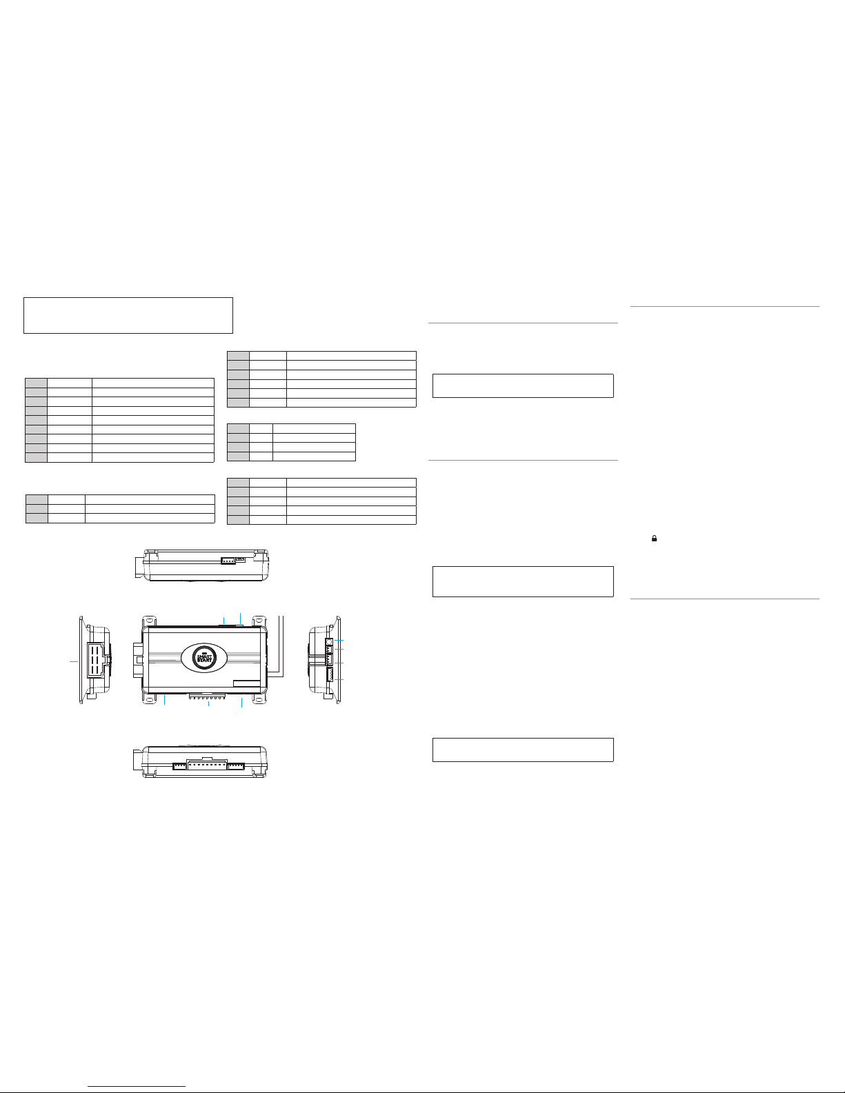
Control Button
(Valet Switch)
Door Lock/unlock
Harness
Side View
Antenna
Antenna
LED (Programming
indicator)
Parking light Jumpers
Primary Harness Remote Start Harness
Heavy
Gauge
Relay
Side View
Satellite Harness
Red 4-pin port, Bitwriter/ESP2 or D2D
Wiring Connections
Main Harness (H1), 9-pin connector
H1/1
LIGHT GREEN BLACK (-) 200mA FACTORY ALARM DISARM
H1/2
GREEN/WHITE (-) 200mA FACTORY ALARM REARM
H1/3
YELLOW (+) IGNITION OUT (TO ALARM)
H1/4
WHITE/BLUE (-) ACTIVATION INPUT
H1/5
ORANGE (-) 500mA GROUND WHEN LOCKED/ANTI-GRIND OUTPUT
H1/6
BROWN (-) 200mA HORN OUTPUT
H1/7
RED/WHITE (-) 200mA TRUNK RELEASE OUTPUT
H1/8
BLACK GROUND
H1/9
WHITE (+/-) LIGHT FLASH OUTPUT
Remote start (H2) 6-pin connector
H2/1
PINK OUTPUT TO PRIMARY IGNITION CIRCUIT
H2/2
PURPLE OUTPUT TO STARTER CIRCUIT
H2/3
ORANGE OUTPUT TO ACCESSORY CIRCUIT
H2/4
RED (+) (30A) HIGH CURRENT 12V INPUT
H2/5
PINK/WHITE OUTPUT TO SECOND IGNITION/ACCESSORY CIRCUIT
H2/6
RED (+) (30A) HIGH CURRENT 12V INPUT
Satellite harness - 4-pin connector
1
BLUE (-) 200mA STATUS OUTPUT
2
ORANGE (-) 200mA ACCESSORY OUTPUT
3
PURPLE (-) 200mA STARTER OUTPUT
4
PINK (-) 200mA IGNITION OUTPUT
Remote Start harness (H3), 5-pin connector
H3/1
BLACK/WHITE (-) NEUTRAL SAFETY SWITCH INPUT
H3/2
VIOLET/WHITE TACHOMETER INPUT WIRE
H3/3
BROWN (+) BRAKE SHUTDOWN INPUT WIRE
H3/4
GRAY (-) HOOD PIN SWITCH SHUTDOWN WIRE
H3/5
BLUE/WHITE (-) 200 mA 2ND STATUS/REAR DEFOGGER
Installation Points
Tach Learning
To learn the tach signal:
1. Start the vehicle with the key.
2. Within 5 seconds, press and hold the Valet button.
3. After 3 seconds the LED will light constant when the tach signal is learned.
4. Release the Valet button.
Important: This unit can learn the tachometer with the analog input or
through D2D using an interface module. The unit confirms which source
is used.
When programming tach learning with:
• Analog, the parking lights flash one time
• D2D inerface module, the parking lights flash twice
If the tachometer input on the system is connected to the vehicle, the D2D tachometer
input will be ignored.
Virtual Tach
Note: Virtual tach is not recommended for diesel trucks
To program Virtual Tach:
1. After the install is complete, remote start the car.
2. If the car does not start on the first attempt, let the remote start attempt again.
3. Once the car starts, let it run until the parking lights come on.
4. When the parking lights come on, shut off the remote start with the remote that’s it! Virtual Tach is programmed.
Virtual Tach handles disengaging the starter motor during remote starting – it does
not address over-rev. If the customer wants to have the over-rev protection capability, the tach wire must be connected. This may involve more installation shop
charges than initially quoted.
Important: If the Virtual Tach mode over cranks or doesn't crank the
vehicle long enough to start and run the car, use the Bitwriter to add or
subtract the starter output time. You can adjust the output time in increments of 50msec of the learned time using the Bitwriter.
Red 4-pin port, Bitwriter/ESP2 or D2D programming
The Red 4-pin plug may be configured as a Bitwriter/ESP2 or D2D port.
The factory default is Bitwriter/ESP2 mode.
To use as D2D mode follow the below steps:
1. Make sure White/Blue activation wire is grounded.
2. Power the unit up. The system LED flashes for 5 seconds to confirm D2D mode
change.
3. Remove the White/Blue wire from ground.
To change from D2D to Bitwriter/ESP2 mode:
1. Make sure the White/Blue activation wire is grounded.
2. Power the unit up, the system LED turns on solid for 5 seconds to confirm Bitwriter/ESP2 mode change.
3. Remove the White/Blue wire from ground.
The procedure can be repeated to toggle from one mode to the other.
Important: If you power up the system with the White/Blue activation
wire ungrounded, the system LED will come on solid for 5 seconds indicating the system is in Bitwriter/ESP2 mode.
Reset and Deletion
If a feature/virtual tach needs to be reset or the remote controls need to be deleted,
use the following procedure.
1. Turn the ignition to the ON position (The heavy gauge pink wire must be connected).
2. Within 10 seconds, press and release the Valet button: 2 times if you want to
delete remotes, 3 times to reset features or 4 times to reset virtual tach. These
features are described next.
Delete remotes: This feature erases all remotes from the memory of the
system. This is useful in cases when a customer’s remote is lost or stolen.
Note: This does not reset the programmed features of the system or reset
the Virtual Tach setting.
Reset Features: This resets all features of the system to the factory default
settings.
Note: This feature does not delete the remotes from the system or reset
the Virtual Tach setting
Virtual Tach Reset: Deletes all previously learned values for Virtual Tach,
and on the next remote start sequence the unit begins virtual tach initialization.
Note: The “Zap” feature on the Bitwriter does not reset the Virtual tach
setting.
3. Once you have selected the function step, press the Valet button once more
and hold it. The LED flashes and the horn honks to confirm the selected functional step. Do not release the Valet button
4. While holding the Valet button, Activate remote start input. When the white/
5. blue H1/4 is pulsed, the horn sounds to confirm the reset.*
* If using the optional RF kit p/n: 9474T (1-way remote and receiver), press
the
button on the remote control to reset features.
Once the feature is reset, the Valet button can be released.
Remote Start Shutdown Diagnostics
To perform shutdown diagnostics:
1. With the ignition Off, press and hold the Valet button.
2. Turn the ignition On and then back Off while holding the Valet button.
3. Release the Valet button.
4. Press and release the Valet button. The LED flashes to report the last
shutdown for one minute or until the ignition is turned on, as shown in the
following table:
LED Flashes Shutdown Mode
1 flash Timed out
2 flashes Over-rev shutdown
3 flashes Low or no RPM, low battery (voltage and virtual tach modes)
4 flashes Transmitter shutdown (or optional push button)
5 flashes (-) Hood Shutdown (H3/4 GRAY)
6 flashes (+) Shutdown (H3/3 BROWN)
7 flashes (-) Neutral safety shutdown (H3/1 BLACK/WHITE)
8 flashes Wait-to-start timed out
Door Lock, 3-pin connector
1
BLUE (-) UNLOCK
2
EMPTY NOT USED
3
GREEN (-) LOCK
Page 2
© 2011 Directed Electronics. All rights Reserved.
2
QRNADSS4003 2011 -12
Programming System Features
The System Features Learn Routine dictates how the unit operates. It is possible to access and change most of the
feature settings using the Valet button.
1. Turn the ignition on, then off.
2. Select a Menu. Press and hold the Valet button. The number of LED flashes and horn honks indicates the
menu number. A single LED flash and honk indicates menu 1. Two LED flashes and 2 honks indicates menu
2.
3. When the desired menu LED flashes and honks are heard, release the Valet button.
4. Select a Feature. Press and release the Valet button the number of times corresponding to the feature you
wish to change. Then press and hold one more time to select the feature. The LED flashes and the horn
honks to indicate which feature is selected.
5. Program the Feature. While holding the Valet button, Pulse the white/blue H1/4 wire, the LED will turn on
or off indicating the feature setting. If the feature has more than two selections, each time this input is pulsed
the next available setting will be picked. For example if 60 minute runtime is chosen, (Menu 2 feature 2) the
LED flashes 3 times.
If using optional 9474T RF kit
This is the alternative to step 5: Program the Feature. While holding the Valet button, you can program the feature
using the remote control. For features with only two options;
= option 1 while
= option 2.
For features with more than two options;
selects the options in ascending order. The LED flashes and the horn
honks indicating which option is selected.
Once a feature is programmed:
• Other features can be programmed within the same menu
• Another menu can be selected
• The learn routine can be exited if programming is complete
To access another feature in the same menu:
1. Press and release the Valet button the number of times necessary to advance from the feature you just programmed to the next one you want to program.
2. Then press the Valet button once more and hold it.
To select another menu:
1. Press and hold the Valet button.
2. After 3 seconds, the unit advances to the next menu, the horn honks and LED flashes indicating which menu
has been accessed.
The learn routine exits if any of the following occurs:
• The ignition is turned On
• There is no activity for 30 seconds
• The Valet button is pressed too many times
Bitwriter - Only Options
If programming with the Bitwriter®, the learn routine can be locked or unlocked. If the learn routine has
previously been locked, it must be unlocked with Bitwriter® - this cannot be done manually with the Valet
button.
The Bitwriter® gives you access to a wider range of system options. These features and the adjustments that
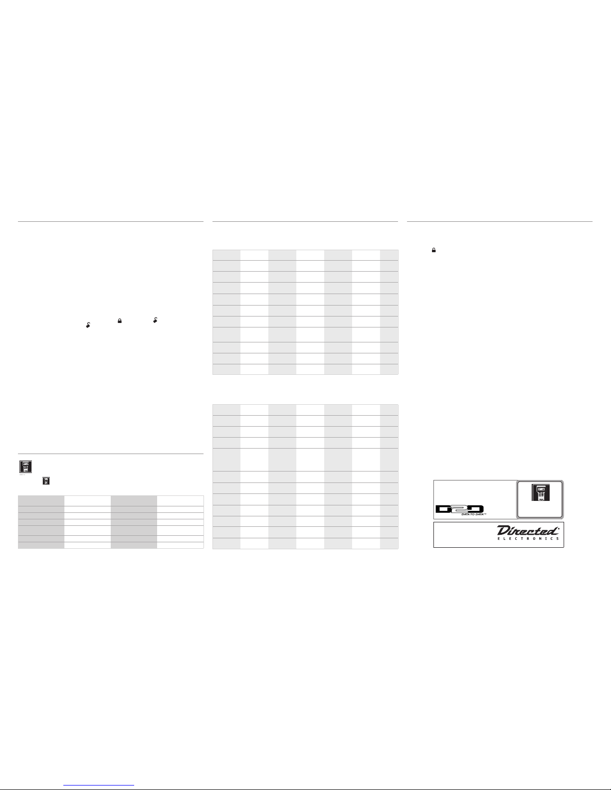
may be programmed are described in the table below.
Menu Item Feature Default Options
1
Engine Runtime
12 min.
1-60 min.
2
Diesel start type
Off
Timed
3
Diesel start delay time (seconds)
15 sec
1-90 sec.
4
Virtual Tach Fine Tune
Not initialized
0 to 1 second in 50 millisecond
increments
5
Remote control programming
Unlocked
Locked
6
Feature Programming
Unlocked
Locked
Feature Menus
Default settings are in bold typ e.
Menu 1
Feature # Feature Opt. 1 Opt. 2 Opt. 3 Opt.4 Opt. 5+
1 Horn function
Off
Siren
20 mS
Siren
30 mS
Siren
40 mS
Siren
50 mS
2 Ignition con-
trolled lock
On
Off
3 Ignition con-
trolled unlock
On
Off
4 Doorlock out-
put duration
0.8 sec
.
3.5 sec. 0.4 sec.
5 Double pulse
unlock
Off
On
6 Double pulse
lock
Off
On
7 Factory Alarm
Disarm function
with unlock
Before unlock Remote start
only
8 Factory Alarm
Disarm Pulses
Single
Double
9 Comfort
Closure
Comfort
Closure 1
Off
Comfort
Closure 2
10 Panic
On
Off
Menu 2
Feature # Feature Opt. 1 Opt. 2 Opt. 3 Opt.4 Opt. 5+
1 Engine check-
ing
Virtual tach
voltage Off tachometer
2 Engine
Runtime
12 min
24 min 60 min
3 Park light
output
Pulsed
Constant
4 Cranking time
0.6 sec
.
0.8 sec. 1.0 sec. 1.2 sec. 1.4,
1.6,
1.8,
2.0,
4.0 sec
5 Activation
pulse count
1 pulse
2 pulses 3 pulses
6 2nd Ignition
behavior
Ignition
Accessory
7 Accessory
output
Off during
wait-to-start
On during
wait-to-start
8 2nd Status
behavior
Normal
Latch rear
defogger
Pulse rear
defogger
9 Anti-grind
On
Off
10 Diesel start
delay
Off
Timed 15 sec Timed 30 sec. Timed 45 sec.
11 Timer mode
run time
12 min
3 min 6 min 9 min
Optional Remote Programming (for use when adding 9474T Remote Kit)
1. Turn key to the ON position
2. Within 5 seconds, press and release Valet button one time.
3. Within 5 seconds, press and hold the Valet button. The LED will flash one time and the horn honks to confirm
entry into remote programming.
4. Press the
button on the remote control.
5. The horn honks to confirm the remote has been programmed.
6. Release the Valet button, and turn the key to the Off position.
7. The horn sounds one long honk to confirm that remote programming has been exited.
The programming routine exits if any of the following occurs:
The ignition is turned off
There is no activity for 30 seconds
The Valet button is pressed too many times
Bitwriters with a date code of 6a or older require an IC
upgrade (p/n 998M). Some bitwriters with a date code
of 6B do not require the IC upgrade, refer to tech tip #
1112 for more information.
The Bitwriter® (p/n 998U)
requires chip version 2.7 or
newer to program this unit.
See full Installation Guide for more
detailed information on this system.
Such information and more can be
found online at:
www.directechs.com
Logo, Directed with designed in USA.eps
 Loading...