

Page 1

20402 & 29402
VATS / PASSLOCK / TRANSPONDER
Universal Alarm Bypass Module
English p1
Français p17
Español p29
Page 2
© 2006 Directed Electronics 1 N20402 08-06
VATS / PASSLOCK / TRANSPONDER
Universal Alarm Bypass Module
Model #s 20402 & 29402
This module lets you bypass virtually any type of factory passive anti-theft system
on the market today to remotely start your vehicle without permanently disabling
the vehicle’s anti-theft system.
In 1983, General Motors came out with their rst Vehicle Anti- Theft System
known as VATS which uses a resistor pellet in the key. Since that time, other more
sophisticated theft systems have followed. These theft systems are still resistance
based, and use a “Transponder” which is a tiny pellet or chip embeded within the
the head of the ignition key.
Contents:
1 Universal Alarm Bypass Module
1 8 position wire harness
1 Transponder loop w/connector
2 Cable Ties
1 Instruction booklet
2 Double-stick foam tape
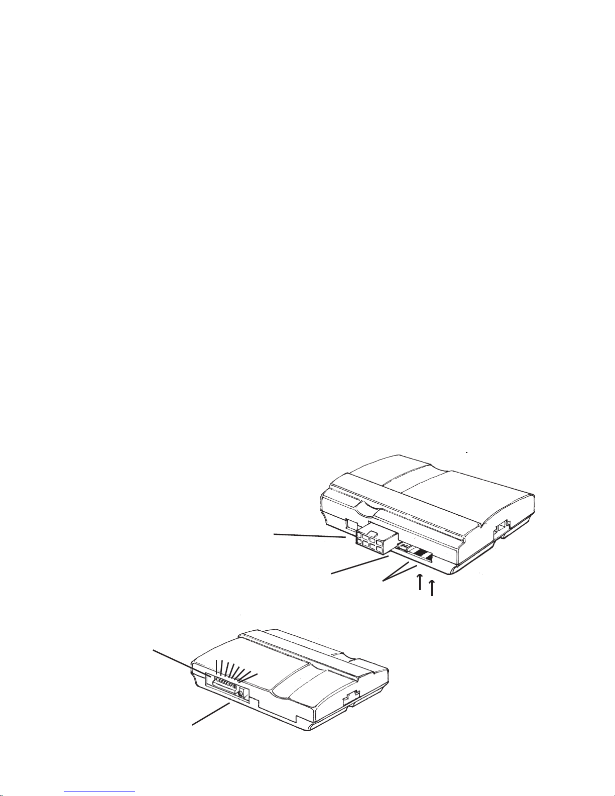
8 position harness
connector
Transponder Loop
connector
2 Resistor
Measuring Pads
8 position
dip-switch
Variable Resistor
FRONT VIEW
BACK VIEW
Up is OFF
Down is ON
1 2 3 4 5 6 7 8
Page 3

N20402 08-06 2 © 2006 Directed Electronics
List of vehicles and the types of security systems
Lista de Vehículos y tipos de sistemas de seguridad:
Make Model Year Immobilizer
Type
Cadillac Escalade Ext 2002-06 Passlock II
Cadillac Seville 1998-2004 Transponder
Cadillac SRX 2004-06 Transponder
Cadillac Catera 1997-2001 Transponder
Cadillac DTS 2006 Transponder
Cadillac SRX 2004-06 Transponder
Cadillac Allante 1991-93 VATS
Cadillac Brougham 1990-95 VATS
Cadillac De Ville 1990-99 VATS
Cadillac Eldorado 1990-2002 VATS
Cadillac Fleetwood 1990-96 VATS
Cadillac Seville 1990-97 VATS
Chevrolet Astro 1998-2005 Passlock II
Chevrolet Avalanche 2002-06 Passlock II
Chevrolet Blazer 1998-2005 Passlock II
Chevrolet Express Van 1998-2006 Passlock II
Chevrolet Impala 2000-06 Passlock II
Chevrolet Monte Carlo 2000-05 Passlock II
Chevrolet S-10 Pickup 1998-2004 Passlock II
Chevrolet Silverado 1999-2006 Passlock II
Chevrolet Suburban 1998-2006 Passlock II
Chevrolet Tahoe 1998-2006 Passlock II
Chevrolet Trailblazer 2002-06 Passlock II
Chevrolet Venture 2000-05 Transponder
Chevrolet Cavalier 1995-2005 Passlock I
Chevrolet Equinox 2005-06 Passlock II
Chevrolet Malibu 1997-2006 Passlock II
Chevrolet Monte Carlo 2000-05 Passlock II
Chevrolet S-10 Pickup 1998-2004 Passlock II
Chevrolet Silverado 1998-2005 Passlock II
Chevrolet SSR 2003-06 Passlock II
Chevrolet Aveo 2004-06 Transponder
Chevrolet Impala 2006 Transponder
Chevrolet Uplander 2005-06 Transponder
Make Model Year Immobilizer
Type
Acura CL 1998-2003 Transponder
Acura Integra 2000-01 Transponder
Acura MDX 2001-06 Transponder
Acura TL 1999-2006 Transponder
Acura TSX 2004-06 Transponder
Acura NSX 1997-2005 Transponder
Acura RL 1996-2004 Transponder
Audi A4 2000-04 Transponder
Audi A6 2000-04 Transponder
Audi A8 2000-03 Transponder
Audi Allroad 2001-04 Transponder
Audi S4 2002 Transponder
Audi TT 2000-04 Transponder
Buick LaCrosse 2005-06 Transponder
Buick LeSabre 2000-05 Transponder
Buick Park Avenue 2000-05 Transponder
Buick Rainier 2004-06 Passlock II
Buick Rendezvous 2002-06 Transponder
Buick LeSabre 2000-05 Transponder
Buick Park Avenue 1997-2005 Transponder
Buick Skylark 1996-98 Passlock I
Buick LaCrosse 2005-06 Transponder
Buick Lucerne 2006 Transponder
Buick Terraza 2005-06 Transponder
Buick Century 1993 VATS
Buick Century 1994-2005 VATS
Buick Reatta 1990-91 VATS
Buick Regal 1993-2004 VATS
Buick Riviera 1990-99 VATS
Buick Roadmaster 1993-96 VATS
Cadillac CTS 2003-06 Transponder
Cadillac De Ville 2000-05 Transponder
Cadillac Escalade 1999-2006 Passlock II
Cadillac Escalade ESV 2003-06 Passlock II
Liste de véhicules avec leurs types de systèmes de sécurité
English Français
Transponder = Transpondeur
VATS = SAV
Page 4

© 2006 Directed Electronics 3 N20402 08-06
Chevrolet Camaro 1986-2002 VATS
Chevrolet Caprice 1993-96 VATS
Chevrolet Corvette 1984-2004 VATS
Chevrolet Impala 1994-96 VATS
Chevrolet Lumina 1993-2000 VATS
Chevrolet Monte Carlo 1995-99 VATS
Chevrolet Monte Carlo 2001-06 Passlock II
Chrysler 300M 1999-2004 Transponder
Chrysler Cirrus 2000 Transponder
Chrysler Concorde 1998-2004 Transponder
Chrysler LHS 1999-2001 Transponder
Chrysler Prowler 2001-02 Transponder
Chrysler PT Cruiser 2001-05 Transponder
Chrysler Sebring Convert-
ible
1998-2005 Transponder
Chrysler Sebring Sedan 2001-05 Transponder
Chrysler Town and Country 2001-03 Transponder
Chrysler Voyager 2001-03 Transponder
Chrysler 300 2005-06 Transponder
Chrysler Pacica 2004-06 Transponder
Chrysler PT Cruiser 2006 Transponder
Chrysler Town and Country 2004-05 Transponder
Chrysler Crossre 2004-05 Transponder
Chrysler Sebring Coupe 2001-05 Transponder
Dodge Caravan 2001-03 Transponder
Dodge Dakota pickup 2001-04 Transponder
Dodge Durango 2001-03 Transponder
Dodge Intrepid 1998-2004 Transponder
Dodge Neon 2000-05 Transponder
Dodge Ram Pickup 2002-05 Transponder
Dodge Stratus 2000 Transponder
Dodge Stratus Sedan 2001-05 Transponder
Dodge Caliber 2007 Transponder
Dodge Caravan 2004-05 Transponder
Dodge Charger 2006 Transponder
Dodge Dakota pickup 2005 Transponder
Dodge Magnum 2005-06 Transponder
Dodge Durango 2004-06 Transponder
Dodge Ram Pickup 2006 Transponder
Dodge Sprinter 2003-05 Transponder
Dodge Stratus Coupe 2001-05 Transponder
Ford Contour 1998-2000 Transponder
Ford Crown Victoria 1998-2006 Transponder
Ford Escape 2001-06 Transponder
Ford Excursion 2000-05 Transponder
Ford Expedition 1997-2006 Transponder
Ford Explorer 1998-2006 Transponder
Ford Explorer Sport
Trac
2001-05 Transponder
Ford F Series Light
Duty
1998-2006 Transponder
Ford Five Hundred 2005-06 Transponder
Ford Focus 2000-06 Transponder
Ford Freestar 2004-06 Transponder
Ford Freestyle 2005-06 Transponder
Ford Fusion 2006 Transponder
Ford GT 2005-06 Transponder
Ford Mustang 1996-2006 Transponder
Ford Ranger 1998-2006 Transponder
Ford Taurus 1998-2006 Transponder
Ford Thunderbird 1997,
2002-05
Transponder
Ford Windstar 1999-2003 Transponder
Ford Taurus 1996-97 Transponder
GMC Denali 1999-2001 Passlock II
GMC Envoy 1999-2006 Passlock II
GMC Envoy XL 2002-06 Passlock II
GMC Envoy XUV 2004-05 Passlock II
GMC Safari 1998-2005 Passlock II
GMC Safari 2005 Passlock II
GMC Savana Van 1998-2006 Passlock II
GMC Sierra 1998-2006 Passlock II
GMC Sonoma 1998-2004 Passlock II
GMC Yukon 1999-2006 Passlock II
GMC Yukon XL 2000-06 Passlock II
GMC Jimmy 1998-2001 Passlock II
GMC Suburban 1998-2006 Passlock II
Honda Prelude 1997-2001 Transponder
Honda Accord 1998-2006 Transponder
Honda Civic 2001-06 Transponder
Honda CR-V 2002-06 Transponder
Honda Element 2003-05 Transponder
Honda Fit 2007 Transponder
Honda Odyssey 1999-2006 Transponder
Honda Pilot 2003-05 Transponder
Honda Ridgeline 2006 Transponder
Honda Accord Hybrid 2005 Transponder
Honda Insight 2000-05 Transponder
Honda Odyssey 1998 Transponder
Page 5

N20402 08-06 4 © 2006 Directed Electronics
Honda S2000 2000-05 Transponder
Hummer H2 2003-05 Transponder
Hyundai Accent 2004-05 Transponder
Hyundai Azera 2006 Transponder
Hyundai Elantra 2001-05 Transponder
Hyundai Santa Fe 2003-05 Transponder
Hyundai Sonata 2004-06 Transponder
Hyundai Tiburon 2003-05 Transponder
Hyundai Tucson 2005 Transponder
Hyundai XG300 2001 Transponder
Hyundai XG350 2002-05 Transponder
Inniti FX35/FX45 2003-05 Transponder
Inniti G20 2000-02 Transponder
Inniti G35 Coupe 2003-05 Transponder
Inniti G35 Sedan 2003-05 Transponder
Inniti I30 1999-2001 Transponder
Inniti I35 2002-04 Transponder
Inniti M45 2003-04 Transponder
Inniti Q45 1998-2005 Transponder
Inniti QX4 1999-2003 Transponder
Inniti QX56 2004-05 Transponder
Isuzu Ascender 2003-06 Passlock II
Isuzu Hombre 1998-2000 Passlock II
Isuzu Axiom 2003-04 Transponder
Isuzu Rodeo 2003-04 Transponder
Isuzu Rodeo Sport 2003 Transponder
Jaguar S-type 2000-05 Transponder
Jaguar XJ Series 2004-05 Transponder
Jaguar XJ8 1998-2003 Transponder
Jaguar XJR 1998-2003 Transponder
Jaguar XK Series 2004 Transponder
Jaguar XK Series 2005 Transponder
Jaguar XK8 1998-2003 Transponder
Jaguar XKR 2000-03 Transponder
Jaguar X-type 2002-05 Transponder
Jeep Cherokee 1999-2001 Transponder
Jeep Grand Cherokee 1999-2005 Transponder
Jeep Liberty 2002-05 Transponder
Jeep Wrangler 1998-2005 Transponder
Jeep Commander 2006 Transponder
Kia Amanti 2004-05 Transponder
Kia Optima 2005 Transponder
Kia Spectra (2.0L) 2004-05 Transponder
Kia Sportage 2005 Transponder
Land Rover Discovery Series II 2000-04 Transponder
Land Rover Freelander 2002-05 Transponder
Land Rover LR3 2005 Transponder
Land Rover Range Rover 1999-2005 Transponder
Lexus ES 300 1998-2003 Transponder
Lexus GS 300 1998-2005 Transponder
Lexus GS 400 1998-2000 Transponder
Lexus GS 430 2001-05 Transponder
Lexus IS 300 2001-05 Transponder
Lexus LS 400 1998-2000 Transponder
Lexus LX 470 1998-2002 Transponder
Lexus RX 300 1998-2003 Transponder
Lexus SC 300 1998-2000 Transponder
Lexus SC 400 1998-2000 Transponder
Lexus ES 330 2004-06 Transponder
Lexus GX 470 2003-06 Transponder
Lexus LS 400 1997 Transponder
Lexus LS 430 2001-06 Transponder
Lexus LX 470 2003-06 Transponder
Lexus RX 330 2004-06 Transponder
Lexus RX 400h 2006 Transponder
Lexus SC 430 2002-06 Transponder
Lincoln Aviator 2003-05 Transponder
Lincoln Blackwood 2002 Transponder
Lincoln Continental 1998-2002 Transponder
Lincoln LS 2000-06 Transponder
Lincoln Mark LT 2006 Transponder
Lincoln Navigator 1998-2006 Transponder
Lincoln Town Car 1998-2006 Transponder
Lincoln Zephyr 2006 Transponder
Lincoln Mark VIII 1997-98 Transponder
Mazda 3 2004-05 Transponder
Mazda 6 2003-05 Transponder
Mazda B 2500, B 3000,
B 4000
1999-2000 Transponder
Mazda B Series 2001-05 Transponder
Mazda RX-8 2004-05 Transponder
Mazda Tribute 2001-05 Transponder
Mazda 5 2006 Transponder
Mazda 626 1998-2002 Transponder
Mazda CX-7 2007 Transponder
Mazda Miata 2001-06 Transponder
Mazda Millenia 1998-2002 Transponder
Mazda MPV 2000-05 Transponder
Mercedes
Benz
C 230 1998-2000 SWITCH-
BLADE
KEYS ONLY
Page 6

© 2006 Directed Electronics 5 N20402 08-06
Mercedes
Benz
C 280 1998-2000 SWITCH-
BLADE
KEYS ONLY
Mercedes
Benz
C Class 2001-02 SWITCH-
BLADE
KEYS ONLY
Mercedes
Benz
CL Class 1998-99 SWITCH-
BLADE
KEYS ONLY
Mercedes
Benz
CLK Class 1998 SWITCH-
BLADE
KEYS ONLY
Mercedes
Benz
CLK Class 1999-2002 SWITCH-
BLADE
KEYS ONLY
Mercedes
Benz
E Class 1997-2002 SWITCH-
BLADE
KEYS ONLY
Mercedes
Benz
ML 320 1998-2000 SWITCH-
BLADE
KEYS ONLY
Mercedes
Benz
ML 430 1999-2000 SWITCH-
BLADE
KEYS ONLY
Mercedes
Benz
ML Class 2001-02 SWITCH-
BLADE
KEYS ONLY
Mercedes
Benz
S 320 1997 SWITCH-
BLADE
KEYS ONLY
Mercedes
Benz
S 420 1997 SWITCH-
BLADE
KEYS ONLY
Mercedes
Benz
S 500 1997 SWITCH-
BLADE
KEYS ONLY
Mercedes
Benz
S Class 1998-2002 SWITCH-
BLADE
KEYS ONLY
Mercedes
Benz
SL Class 1998-99 SWITCH-
BLADE
KEYS ONLY
Mercedes
Benz
SLK Class 1998-2002 SWITCH-
BLADE
KEYS ONLY
Mercury Cougar 1999-2002 Transponder
Mercury Grand Marquis 1999-2006 Transponder
Mercury Marauder 2003-04 Transponder
Mercury Mariner 2005-06 Transponder
Mercury Milan 2006 Transponder
Mercury Montego 2005-06 Transponder
Mercury Monterey 2004 Transponder
Mercury Monterey 2005-06 Transponder
Mercury Mountaineer 1998-2006 Transponder
Mercury Mystique 1998-2000 Transponder
Mercury Sable 1996-2005 Transponder
Mercury Cougar 1997 Transponder
Mercury Grand Marquis 1998 Transponder
Mercury Mountaineer 1997 Transponder
Mini Cooper 2002-05 Transponder
Mitsubishi Diamante 2000-04 Transponder
Mitsubishi Eclipse 2000-06 Transponder
Mitsubishi Endeavor 2004-05 Transponder
Mitsubishi Galant 2000-05 Transponder
Mitsubishi Lancer 2003-05 Transponder
Mitsubishi Montero 2001-05 Transponder
Mitsubishi Montero Sport 2000-04 Transponder
Mitsubishi Outlander 2004-05 Transponder
Mitsubishi Raider 2006 Transponder
Nissan 350Z 2003-05 Transponder
Nissan Altima 2000-05 Transponder
Nissan Armada 2005 Transponder
Nissan Frontier 2005 Transponder
Nissan Maxima 1999-2005 Transponder
Nissan Murano 2003-05 Transponder
Nissan Pathnder 1999-2005 Transponder
Nissan Pathnder 2000-05 Transponder
Nissan Pathnder Armada 2004 Transponder
Nissan Quest 2004-05 Transponder
Nissan Sentra 2000-05 Transponder
Nissan Titan 2004-05 Transponder
Nissan Xterra 2005 Transponder
Oldsmobile Alero 2000-04 Passlock II
Oldsmobile Aurora 1995-99 VATS
Oldsmobile Aurora 2001-03 Transponder
Oldsmobile Bravada 1999-2004 Passlock II
Oldsmobile Intrigue 1998-2002 Passlock II
Oldsmobile Silhouette 2000-04 Transponder
Oldsmobile Achieva 1996-98 Passlock I
Oldsmobile Cutlass 1997-99 Passlock II
Oldsmobile Cutlass Ciera 1995-96 VATS
Oldsmobile Cutlass Supreme 1995-97 VATS
Oldsmobile Eighty-Eight 1995-97 VATS
Oldsmobile Eighty-Eight LSS 1998-99 VATS
Oldsmobile Ninety-Eight 1992-98 VATS
Oldsmobile Regency 1997-98 VATS
Plymouth Breeze 2000 Transponder
Plymouth Neon 2000-01 Transponder
Plymouth Prowler 1999-2000 Transponder
Pontiac Aztek 2001-05 Passlock II
Pontiac Bonneville 1992-2005 VATS
Pontiac Grand Am 1996-98 Passlock I
Page 7

N20402 08-06 6 © 2006 Directed Electronics
Pontiac Grand Am 1999-2005 Passlock II
Pontiac Montana 2000-05 Transponder
Pontiac Sunre 2000-05 Passlock II
Pontiac Transport 2000 Transponder
Pontiac Grand Prix 2000-05 Transponder
Pontiac Sunre 1995-2005 Passlock I
Pontiac Sunre 1996-99 Passlock I
Pontiac Sunre 2000-05 Passlock II
Pontiac Torrent 2006 Passlock II
Pontiac Montana SV6 2005-06 Transponder
Pontiac Solstice 2006 Transponder
Pontiac Firebird 1986-2002 VATS
Porsche 911 Carrera 993 1995-98 Transponder
Porsche 911 Carrera 996 1999-2004 Transponder
Porsche Boxster 1997-2004 Transponder
Saab 9-3 1999-2004 Transponder
Saab 9-5 1999-2004 Transponder
Saab 9-7X 2005 Transponder
Saturn S-Series 2000-02 Passlock II
Saturn L-Series 2000-05 Passlock II
Saturn S-Series 2000-02 Passlock II
Saturn Vue 2002-05 Passlock II
Saturn Relay 2005-06 Transponder
Saturn Sky 2007 Transponder
Scion tC 2005-06 Transponder
Subaru B9 Tribeca 2006 Transponder
Subaru Forester 2005-06 Transponder
Subaru Impreza 2005-06 Transponder
Subaru Legacy 2005-06 Transponder
Subaru Outback 2005-06 Transponder
Suzuki Grand Vitara 2006 Transponder
Suzuki Verona 2004-06 Transponder
Toyota 4Runner 1999-2002 Transponder
Toyota Avalon 1998-2004 Transponder
Toyota Camry 1998-2004 Transponder
Toyota Highlander 2001-03 Transponder
Toyota Land Cruiser 1998-2002 Transponder
Toyota RAV4 2001-03 Transponder
Toyota Sequoia 2001-02 Transponder
Toyota Sienna 1999-2003 Transponder
Toyota Solara 1999-2003 Transponder
Toyota 4Runner 2003-06 Transponder
Toyota Avalon 2005-06 Transponder
Toyota Camry 2005-07 Transponder
Toyota Corolla 2005-06 Transponder
Toyota Highlander 2004-06 Transponder
Toyota Highlander Hybrid 2006 Transponder
Toyota Land Cruiser 2003-06 Transponder
Toyota Matrix 2005-06 Transponder
Toyota MR2 2000-05 Transponder
Toyota Prius 2001-05 Transponder
Toyota RAV4 2004-06 Transponder
Toyota Sequoia 2003-06 Transponder
Toyota Sienna 2004-06 Transponder
Toyota Solara 2004-06 Transponder
Toyota Tacoma 2005-06 Transponder
Toyota Yaris 2006-07 Transponder
Volkswagen Beetle 1999-2004 Transponder
Volkswagen Cabrio 2000-02 Transponder
Volkswagen Eurovan 2001-03 Transponder
Volkswagen Golf w/ power
windows
2000-04 Transponder
Volkswagen Golf w/o power
windows
2000-04 Transponder
Volkswagen GTI w/ power
windows
2000-04 Transponder
Volkswagen GTI w/o power
windows
2000-04 Transponder
Volkswagen Jetta V 2005 Transponder
Volkswagen Jetta w/ power
windows
2000-04 Transponder
Volkswagen Jetta w/o power
window
2000-04 Transponder
Volkswagen Passat 2000-04 Transponder
Volvo C70 1998-2004 Transponder
Volvo S40 2000-2005 Transponder
Volvo S60 2001-04 Transponder
Volvo S70 1998-2000 Transponder
Volvo S80 1999-2004 Transponder
Volvo S90 1998-99 Transponder
Volvo V40 2000-04 Transponder
Volvo V50 2005 Transponder
Volvo V70 1998-2004 Transponder
Volvo V90 1998-99 Transponder
Volvo XC70 2003-04 Transponder
Volvo XC90 2003-04 Transponder
Page 8

© 2006 Directed Electronics 7 N20402 08-06
Determine which type system you have in your vehicle. If unsure -- follow the
chart on the previous pages to determine the system you have. There are several
types of systems as outlined below:
General Motors VATS and PASSLOCK 1 and PASSLOCK 2 theft systems. For
these, you will be required to dial-in a resistor value which matches the one on your
security system. The method is described on the following pages for each type
system using the dip switches and the variable resistor. The variable resistor is a
10 turn potentiometer which can be dialed up from zero ohms to 1,000 ohms.
SATURN vehicles up to the 2000 model year simply hook up to the Universal
Alarm Bypass Module as shown on page 13. If you have a 2000 model year or
later Saturn vehicle, see page 14.
TRANSPONDER / PASSKEY 3 / P.A.T.S. systems require a transponder (or
extra key) to be used with our system. Follow the directions beginning on page
14.
Page 9

N20402 08-06 8 © 2006 Directed Electronics
Dip Switch # 2 3 4 5 6
Resistor Value 0.825 1.65 3.32 6.65 13.3 Final Resistance (k ohms)
ON ON ON ON ON 0.000 +Variable Resistor Value
OFF ON ON ON ON 0.825 +Variable Resistor Value
ON OFF ON ON ON 1.650 +Variable Resistor Value
OFF OFF ON ON ON 2.475 +Variable Resistor Value
ON ON OFF ON ON 3.320 +Variable Resistor Value
OFF ON OFF ON ON 4.145 +Variable Resistor Value
ON OFF OFF ON ON 4.970 +Variable Resistor Value
OFF OFF OFF ON ON 5.795 +Variable Resistor Value
ON ON ON OFF ON 6.650 +Variable Resistor Value
OFF ON ON OFF ON 7.475 +Variable Resistor Value
ON OFF ON OFF ON 8.300 +Variable Resistor Value
OFF OFF ON OFF ON 9.125 +Variable Resistor Value
ON ON OFF OFF ON 9.970 +Variable Resistor Value
OFF ON OFF OFF ON 10.795 +Variable Resistor Value
ON OFF OFF OFF ON 11.620 +Variable Resistor Value
OFF OFF OFF OFF ON 12.445 +Variable Resistor Value
ON ON ON ON OFF 13.300 +Variable Resistor Value
OFF ON ON ON OFF 14.125 +Variable Resistor Value
ON OFF ON ON OFF 14.950 +Variable Resistor Value
OFF OFF ON ON OFF 15.775 +Variable Resistor Value
ON ON OFF ON OFF 16.620 +Variable Resistor Value
OFF ON OFF ON OFF 17.445 +Variable Resistor Value
ON OFF OFF ON OFF 18.270 +Variable Resistor Value
OFF OFF OFF ON OFF 19.095 +Variable Resistor Value
ON ON ON OFF OFF 19.950 +Variable Resistor Value
OFF ON ON OFF OFF 20.775 +Variable Resistor Value
ON OFF ON OFF OFF 21.600 +Variable Resistor Value
OFF OFF ON OFF OFF 22.425 +Variable Resistor Value
ON ON OFF OFF OFF 23.270 +Variable Resistor Value
OFF ON OFF OFF OFF 24.095 +Variable Resistor Value
ON OFF OFF OFF OFF 24.920 +Variable Resistor Value
OFF OFF OFF OFF OFF 25.745 +Variable Resistor Value
DipSwitch #1 Dip Switch #7 Dip Switch #8
VATS OFF OFF OFF
PASSLOCK 1 ON ON OFF
PASSLOCK 2 OFF OFF OFF
Use this chart with VATS, PASSLOCK 1 and PASSLOCK 2.
All resistor values shown are in ‘K-ohms’ -- or 1,000 ohms. Thus the
1.650 value shown in the third row is 1,650 ohms or 1.65 K ohms.
Page 10
© 2006 Directed Electronics 9 N20402 08-06
VATS:
Before performing this set up, make sure the vehicle will start with the transmitter
if you leave the ignition key in the key cylinder.
1. Put dip switch 1, 7 and 8 into the OFF (up) position
2. Measure the resistance of the key. It should be between 392 ohms and 11,800
ohms. To do this, put the ohm meter probes on each side of the key pellet. This
value should be close to one of the following (all values in ohms): 392, 523, 681,
887, 1.13K, 1.47K, 1.87K, 3.01K, 3.74K, 4.75K, 6.04K, 7.5K, 9.53K, 11.8K.
3. Locate the closest value which is less than your desired value on the chart on
page 8. Set dip-switches 2 through 6 as shown on page 8.
4. Put your ohm meter (multi-meter) probes on the two silver resistance measuring
pads through the opening shown in the drawing -- making good contact with
these two silver pads on the board. (See drawing on page 1). Or put your two
probes into the two holes on the bottom of the case making contact with the
underside of the silver pads. Either contact point method will work.
5. With the probes held rmly, nish reaching the nal resistance value needed
for your system by turning the screw on the variable resistor on the side of the
unit next to the dip switches. Turn the screw until the resistance value matches
the resistance value of the key.
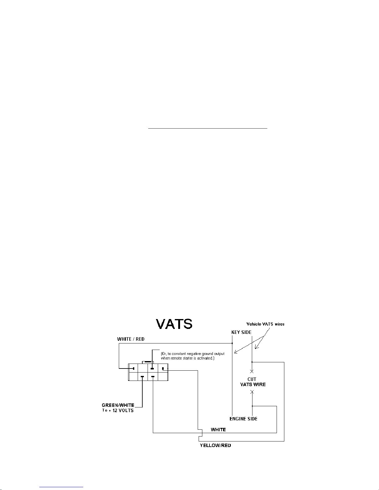
6. Locate the pair of VATS wires (sometimes White/Black striped and Purple/
Black striped). These wires are often in a plastic tube. Be careful not to cut
into the Yellow Air Bag wires! The Air Bag wires are often in a yellow plastic
tube that is clearly marked. The VATS wires run from the ignition switch down
the column under the dash. Connect the Universal Alarm Bypass Module using
the diagram below.
Dip Switch #1 Off
Dip Switch #7 Off
Dip Switch #8 Off
*See page 16 if you do not have a Status wire on your remote
starter
White/Green to Status wire
Page 11

N20402 08-06 10 © 2006 Directed Electronics
PASSLOCK 1:
1. Put dip switches 1 and 7 in the ON (down) position and dip switch 8 in the OFF
(up) position.
2. Remove the bottom half of the steering column shroud.
3. Locate the small three wire harness (with White, Black and Yellow wires)
running down from the ignition key cylinder on the top right hand side of the
steering column into the instrument panel. These wires are usually the smallest
wires in the harness.
4. Cut the Yellow wire in half and strip back both ends. Remove some of the
insulation on the Black wire without cutting the wire. The White wire is not
used.
5. Turn the ignition key to the “ON” or “RUN” position and place the vehicle into
reverse.
6. With the ignition key still in and turned to the “RUN” position, measure the
resistance between the key side of the Yellow wire (connected to the + positive
lead of your digital meter) and the Black wire (connected to the - negative side
of your digital meter).
7. Turn the ignition key to the “START” position and release it. Denote the
resistance reading as this will be the resistance that will need to be duplicated.
Repeat this step several times to verify that you have a consistent reading.
8. When you have identied the correct resistance use the chart on page 8 to set
the resistance on the bypass module. Locate the closest value which is less than
your desired value. Set dip-switches 2 through 6 to match the chart on page 8
for this value.
9. Put your ohm meter (multi-meter) probes on the two silver resistance measuring
pads through the opening shown in the drawing -- making good contact with
these two silver pads on the board. (See drawing on page 1). Or put your two
probes into the two holes on the bottom of the case making contact with the
underside of the silver pads. Either contact point method will work.
10. With the probes held rmly -- dial-in the nal resistance value needed for your
system by turning the screw on the variable resistor on the side of the unit
next to the dip switches. Turn the screw until the resistance value matches the
resistance value of the key.
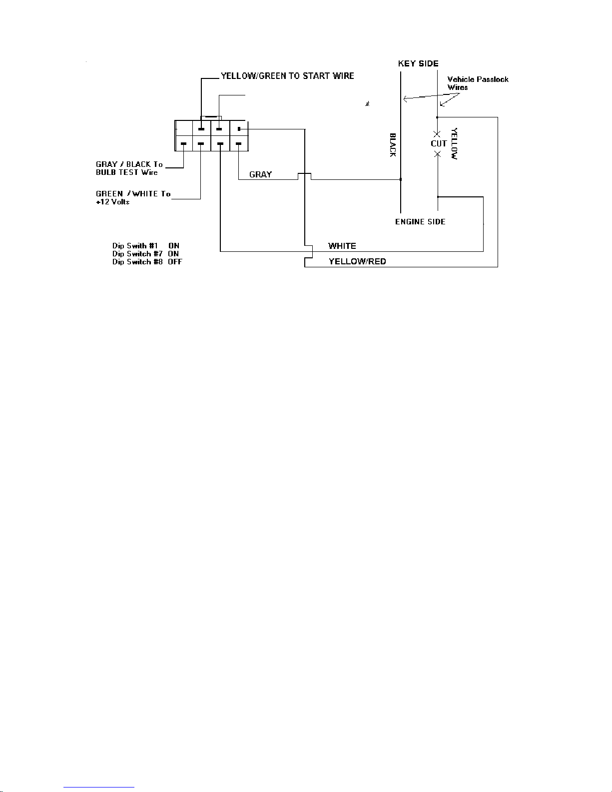
11. Locate the Black “Bulb Test” wire on the left side of the steering column in
cavity “D” or “E” of the Black 5-way connector, just above the main ignition
switch connector. This is a different wire than the Black wire mentioned in
the above steps.
12. Connect the bypass module using the diagram below. Be sure to tape over any
connections to not leave any exposed wires.
Page 12
© 2006 Directed Electronics 11 N20402 08-06
PASSLOCK 2:
1. Turn dip switches 1, 7, and 8 to the OFF (up) position.
2. Remove the bottom half of the steering column shroud.
3. Locate the small three wire harness (with Red/White, Yellow and Orange/
Black wires on trucks and White, Yellow and Black on cars) that come
off the ignition lock cylinder. These are usually the smallest wires.
4. Cut the Yellow wire in half and strip back both ends. Remove the insulation
on the Orange/Black wire (trucks) or the Black wire (cars) without cutting
the wire. The Red/White or White wire is not used.
5. Turn the key to the “Run” position and place the vehicle in Reverse.
6. Connect the key side of the Yellow wire to the + positive lead of your digital
meter and the Black wire (cars) or Orange/Black wire (trucks) to the - nega-
tive lead of your digital meter.
7. Turn the ignition key to the “START” position and release it. Denote the
resistance reading as this will be the resistance that will need to be duplicated.
Repeat this step several times to verify that you have a consistent reading.
*See page 16 if you do not have a Status wire
PASSLOCK 1
To verify the Passlock 1 installation has the correct resistance value
and that the installation is correct -- hold the WHITE/GREEN wire
to ground and start the vehicle with the key. If the vehicle starts
and stays running - the installation is correct.
WHITE/GREEN to WHITE/
BLACK Status wire from
the remote starter.*
Page 13
N20402 08-06 12 © 2006 Directed Electronics
*See page 16 if you do not have a Status wire
8. When you have identied the correct resistance use the chart on page 8 to set
the resistance on the bypass module. Locate the closest value which is less
than your desired value. Set dip-switches 2 through 6 to match the chart on
page 8 with this value.
9. Put your ohm meter (multi-meter) probes on the two silver resistance measuring
pads through the opening shown in the drawing -- making good contact with
these two silver pads on the board. (See drawing on page 1). Or put your two
probes into the two holes on the bottom of the case making contact with the
underside of the silver pads. Either contact point method will work.
10. With the probes held rmly -- dial-in the nal resistance value needed for your
system by turning the screw on the variable resistor on the side of the unit
next to the dip switches. Turn the screw until the resistance value matches
the resistance value of the key.
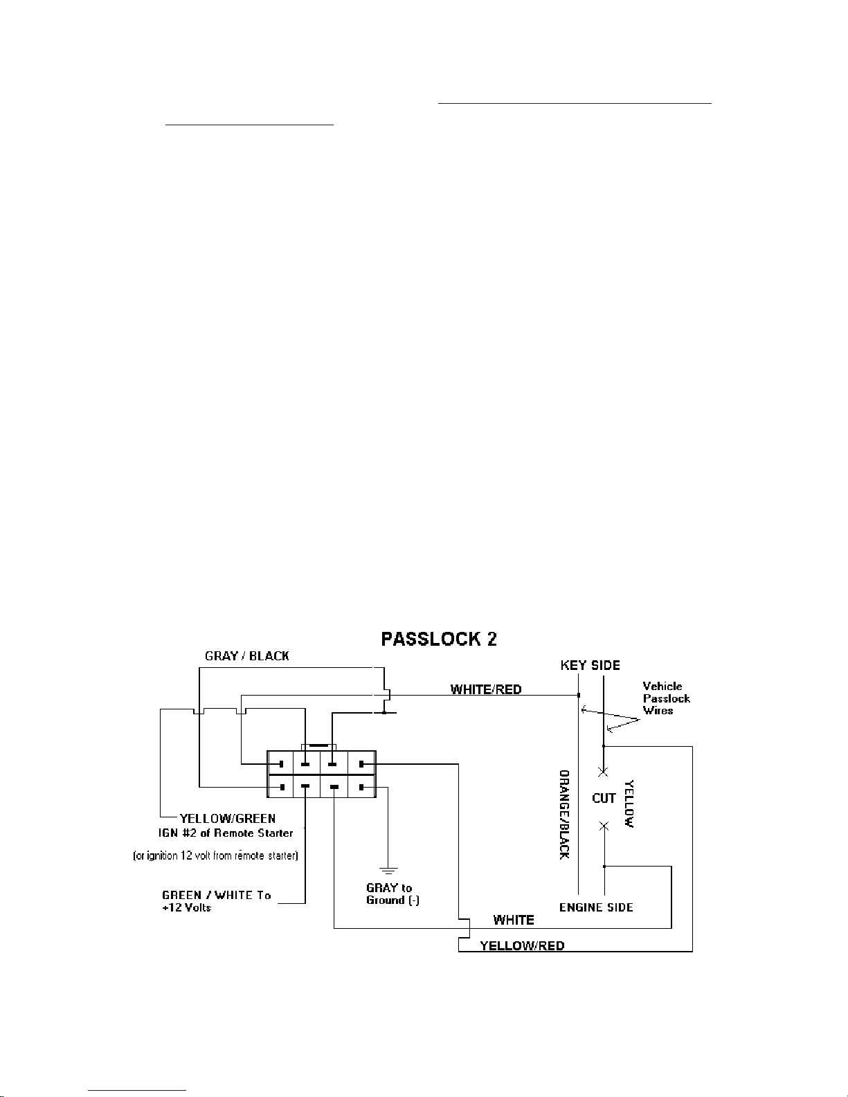
11. Connect the bypass module using the diagram on the next page. Be sure to
tape over any connections to not leave any exposed wires.
To verify that this installation is correct -- hold the WHITE/GREEN wire
and the GRAY/BLACK wire to ground and start the vehicle with the key.
If the vehicle starts and stays running - the installation is correct.
WHITE/GREEN TO WHITE/BLACK
Status output from car starter
(or to constant negative ground
output when remote starter is
Page 14

© 2006 Directed Electronics 13 N20402 08-06
SATURN:
Saturn vehicles up to the 2000 model year with factory keyless entry have a
unique bypass.
1. Set all dip switches to the OFF (up) position.
2. Locate the Alarm Module behind the right rear quarter trim panel (trunk area).
Connect the Pink and Yellow/Black wires of Connector J and D of the alarm
module as shown.
3. Cut the Pink wire in half and connect as shown.
*See page 16 if you do not have a Status wire
Dip Switch #1 Off
Dip Switch #7 Off
Dip Switch #8 Off
WHITE/GREEN TO WHITE/BLACK
Status output from car starter (or
to constant negative ground output
when remote starter is activated).*
Page 15

N20402 08-06 14 © 2006 Directed Electronics
TRANSPONDER / PASSKEY 3 / P.A.T.S.:
‘Smart Key’ & other Transponder systems
Note: For this type of security system - you must sacrice one of the spare keys that
comes with the car. This key will be used for the transponder. The dealership
can progam a spare key, but make sure they program all keys to the vehicle
since learning just one transponder could erase all other key transponders
(including the key used for the Bypass Module).
1. Set all dip switches on the bypass module to the OFF (up) position.
2. Remove the transponder from the key (there maybe a door on the top of the
key that can be opened and the transponder can be removed). Or, the entire
key may be mounted inside the Bypass Module. Be sure to cut the key in half
or grind off some of the teeth to render it unusable.
3. Pull apart the case and place the transponder, or the head of the key, inside the
10 wire loop on the circuit board. Transponders are directional and must be
placed along the same direction that the key would lay. Use the double stick
foam tape provided -- one layer on the circuit board and then the transponder,
or key, and nally the second double-stick foam tape layer on top of it to
hold key securly in place. Make sure the white wires inside the module do not
crisscross each other.
Place Key with Transponder inside case on pc
board as shown. Use double stick tape to hold
to the key in place.
Page 16

© 2006 Directed Electronics 15 N20402 08-06
4. The transponder LOOP goes underneath the steering column and up toward
the ignition key cylinder and needs to be positioned so that there are 2 turns
around the ignition key cylinder as shown below. Transponder systems often
have a black plastic ring around the ignition lock switch. This is the vehicle’s
transponder pick-up antenna. It is important that the two loops of the Bypass
Module be mounted on or as close to this black plastic ring as possible. Slide
the tube up toward the ignition switch to tighten up the loops of wire. Tape in
place to hold. Plug the other end of the transponder loop into the Universal
Alarm Bypass Module.
5. Now start the vehicle with the remote starter. If the vehicle starts and runs
for at least 30 seconds the transponder bypass is correct. Note: If the vehicle
does not start with the remote starter, try adjusting or changing the position
of the transponder in the Bypass Module or adjusting the position of the two
loop wire around the transponder pick-up antenna mentioned above.
Note: The key that the transponder was removed from will no longer start
the vehicle.
White/Green to Status wire of Remote Starter
Page 17

N20402 08-06 16 © 2006 Directed Electronics
For Car Starters that do not have a Status output: You will need a Status
output from your remote car starter for each kind of immobilizer listed on the
preceding pages. Most of our remote starters use the WHITE/BLACK wire in the
control harness as the Status output. If you have a brand of remote car starter that
does not have a Status output, follow the relay hook-up below using Bosch 30 Amp
relays for creating the Status output.
Status output to control
alarm bypass module
Page 18

Français
Page 19

N20402 08-06 18 © 2006 Directed Electronics
SAV / PASSLOCK / TRANSPONDEUR
Module universel de contournement d’alarme
Modèles de série 20402 & 29402
Ce module permet de contourner presque tout type de système antivol passif intégré actuellement sur le marché et de faire démarrer votre véhicule à distance sans
désactiver en permanence son système antivol.
En 1983, General Motors a inventé son premier système antivol, le VATS (SAV
en français), qui utilise une pastille de résistance intégrée à la clé. Depuis lors,
d’autres systèmes plus avancés ont vu le jour. Ils sont encore aujourd’hui basés
sur une résistance et utilisent un transpondeur, une petite pastille ou puce intégrée
à la tête de la clé de contact.
Contenu:
1. 1 module universel de contournement d’alarme
2. 1 faisceau électrique à 8 positions
3. 1 boucle de transpondeur avec raccord
4. 2 attaches de câbles
5. 1 livret d’instructions
6. 2 isolants adhésifs à double face
Raccord de faisceau à 8
positions
Raccord de boucle de
transpondeur
2 contacts de mesure de
résistance
Commutateur DIP à 8
positions
Résistance variable
AVANT
ARRIÈRE
La position relevée est OFF
La position abaissée est
ON
1 2 3 4 5 6 7 8
Page 20

© 2006 Directed Electronics 19 N20402 08-06
Trouvez quel type de système protège votre véhicule. Dans le doute, utilisez le
tableau de la pages précédente (p2 - p6) pour le savoir. Il existe plusieurs types de
systèmes, tel qu’expliqué ci-dessous.
Pour les systèmes antivol SAV, PASSLOCK 1 et PASSLOCK 2 de General Mo-
tors, vous devrez régler la valeur de la résistance pour correspondre à celle de votre
système de sécurité. La méthode est décrite aux pages suivantes pour chaque type
de système. Utilisez les commutateurs DIP et la résistance variable. Cette résistance
est un potentiomètre à dix échelons qui peut être réglé de zéro à 1 000 ohms.
Les véhicules SATURN datant d’avant 2000 sont simplement branchés au mod-
ule universel de contournement d’alarme tel qu’expliqué à la page 25. Si votre
Saturn date de 2000 ou plus tard, référez-vous à la page 26.
Dans le cas des systèmes de type TRANSPONDEUR, PASSKEY 3 et
P.A.T.S., un transpondeur ou une clé supplémentaire devra être utilisée avec
notre système. Suivez les instructions des pages 26 et 27.
Page 21

N20402 08-06 20 © 2006 Directed Electronics
Commutateur Dip # 2 3 4 5 6
Valeur résistance 0.825 1.65 3.32 6.65 13.3 Résistance nale (kilo ohms)
ON ON ON ON ON 0.000 +valeur de résistance variable
OFF ON ON ON ON 0.825 +valeur de résistance variable
ON OFF ON ON ON 1.650 +valeur de résistance variable
OFF OFF ON ON ON 2.475 +valeur de résistance variable
ON ON OFF ON ON 3.320 +valeur de résistance variable
OFF ON OFF ON ON 4.145 +valeur de résistance variable
ON OFF OFF ON ON 4.970 +valeur de résistance variable
OFF OFF OFF ON ON 5.795 +valeur de résistance variable
ON ON ON OFF ON 6.650 +valeur de résistance variable
OFF ON ON OFF ON 7.475 +valeur de résistance variable
ON OFF ON OFF ON 8.300 +valeur de résistance variable
OFF OFF ON OFF ON 9.125 +valeur de résistance variable
ON ON OFF OFF ON 9.970 +valeur de résistance variable
OFF ON OFF OFF ON 10.795 +valeur de résistance variable
ON OFF OFF OFF ON 11.620 +valeur de résistance variable
OFF OFF OFF OFF ON 12.445 +valeur de résistance variable
ON ON ON ON OFF 13.300 +valeur de résistance variable
OFF ON ON ON OFF 14.125 +valeur de résistance variable
ON OFF ON ON OFF 14.950 +valeur de résistance variable
OFF OFF ON ON OFF 15.775 +valeur de résistance variable
ON ON OFF ON OFF 16.620 +valeur de résistance variable
OFF ON OFF ON OFF 17.445 +valeur de résistance variable
ON OFF OFF ON OFF 18.270 +valeur de résistance variable
OFF OFF OFF ON OFF 19.095 +valeur de résistance variable
ON ON ON OFF OFF 19.950 +valeur de résistance variable
OFF ON ON OFF OFF 20.775 +valeur de résistance variable
ON OFF ON OFF OFF 21.600 +valeur de résistance variable
OFF OFF ON OFF OFF 22.425 +valeur de résistance variable
ON ON OFF OFF OFF 23.270 +valeur de résistance variable
OFF ON OFF OFF OFF 24.095 +valeur de résistance variable
ON OFF OFF OFF OFF 24.920 +valeur de résistance variable
OFF OFF OFF OFF OFF 25.745 +valeur de résistance variable
Commutateur Dip#1 Dip #7 Dip #8
SAV OFF OFF OFF
PASSLOCK 1 ON ON OFF
PASSLOCK 2 OFF OFF OFF
Utilisez ce tableau pour les systèmes SAV, PASSLOCK 1 et PASSLOCK 2.
Toutes les valeurs de résistance sont afchées en kilo-ohms (1 000 ohms). Par
exemple, la valeur “1.650” de la troisième rangée correspond à 1 650 ohms ou
1,65 kilo-ohms.
Page 22

© 2006 Directed Electronics 21 N20402 08-06
SAV:
Avant de commencer l’installation, assurez-vous que le transmetteur fait démarrer le véhicule
quand la clé de contact est dans la serrure.
1. Mettez les commutateurs DIP 1, 7 et 8 en position OFF (relevée).
2. Mesurez la résistance de la clé. Elle devrait se situer entre 392 et 11 800 ohms. Pour ce faire,
placez les sondes de l’ohmmètre de chaque côté de la pastille de la clé. La valeur trouvée devrait
être proche de l’une des suivantes (en ohms): 392, 523, 681, 887, 1,13K, 1,47K, 1,87K, 3,01K,
3,74K, 4,75K, 6,04K, 7,5K, 9,53K et 11,8K.
3. Dans le tableau de la page 20, trouvez la valeur la plus proche de la valeur désirée tout en étant
inférieure. Réglez les commutateurs DIP 2 à 6 comme l’indique le tableau.
4. Placez les sondes de votre ohmmètre (multimètre) sur les deux contacts argentés de mesure de
résistance, dans les ouvertures indiquées sur le schéma. Assurez-vous d’établir un bon contact
avec les deux pastilles de la carte (voir le schéma de la page 18). Vous pouvez aussi placer les
deux sondes dans les orices sous le boîtier, et faire contact avec le dessous des contacts argentés.
Les deux méthodes sont bonnes.
5. Les sondes bien en place, ajustez la valeur nale de résistance requise par votre système en tour-
nant la vis de la résistance variable, sur le côté de l’unité, près des commutateurs DIP. Tournez-la
jusqu’à ce que la valeur de la résistance soit égale à celle de la clé.
6. Trouvez la paire de ls SAV (parfois rayés blanc/noir et magenta/noir). Ils sont souvent dans
un tube en plastique. Faites attention à ne pas couper les ls jaunes des coussins gonables!
Ceux-ci sont souvent dans un tube en plastique jaune clairement identié. Les ls SAV vont du
commutateur d’allumage à la colonne sous le tableau de bord. Raccordez le module universel de
contournement d’alarme selon le diagramme ci-dessous.
Commutateur Dip #1 Off
Commutateur Dip #7 Off
Commutateur Dip #8 Off
*Voir page 28 si votre démarreur à distance n’a pas de l de conguration
Fil blanc/vert vers l de conguration
Fils du SAV
SAV
CÔTÉ CLÉ
COUPER LE FIL DU
SAV
CÔTÉ MOTEUR
BLANC
JAUNE/ROUGE
Fil VERT/BLANC vers
borne positive 12 V
ou vers sortie à la masse négative constante
quand le démarreur à distance est activé
BLANC/ROUGE
Page 23

N20402 08-06 22 © 2006 Directed Electronics
PASSLOCK 1:
1. Mettez les commutateurs DIP 1 et 7 en position ON (abaissée) et 8 en position OFF
(relevée).
2. Retirez la moitié inférieure de l’enveloppe de la colonne de direction.
3. Trouvez le petit faisceau à trois ls (ls blanc, noir et jaune) sortant du barillet de la
clé de contact au haut du côté droit de la colonne de direction vers le tableau de bord.
Ces ls sont généralement les plus petits dans le faisceau.
4. Coupez en deux le l jaune et dénudez les deux extrémités. Retirez une partie de
l’isolant du l noir sans couper le l. Le l blanc n’est pas utilisé.
5. Tournez la clé de contact en position “ON” ou “MARCHE” et mettez le véhicule en
marche arrière.
6. La clé de contact toujours en place et en position “MARCHE”, mesurez la résistance
entre le côté clé du l jaune (raccordé à la borne positive du multimètre numérique)
et le l noir (raccordé à la borne négative du multimètre).
7. Tournez la clé de contact en position “DÉMARRER” et relâchez-la. Notez la valeur
de la résistance: vous devrez la reproduire. Refaites l’opération plusieurs fois pour
vous assurer que cette valeur est stable.
8. Une fois la bonne résistance identiée, utilisez le tableau de la page 20 pour régler la
résistance du module de contournement. Trouvez la valeur la plus proche de la valeur
désirée tout en étant inférieure. Réglez les commutateurs DIP 2 à 6 selon le tableau
de la page 20 pour cette valeur.
9. Placez les sondes de votre ohmmètre (multimètre) sur les deux contacts argentés de
mesure de résistance, dans les ouvertures indiquées sur le schéma. Assurez-vous de
faire un bon contact avec les deux pastilles de la carte (voir le schéma de la page 1).
Vous pouvez aussi placer les deux sondes dans les orices sous le boîtier, et faire
contact avec le dessous des contacts argentés. Les deux méthodes sont bonnes.
10. Les sondes bien en place, ajustez la valeur nale de la résistance requise par votre
système en tournant la vis de la résistance variable, sur le côté de l’unité, près des
commutateurs DIP. Tournez-la jusqu’à ce que la valeur de la résistance soit égale à
celle de la clé.
11. Trouvez le l noir “Test de l’ampoule” (“Bulb Test”) sur le côté gauche de la colonne
de direction, dans la cavité D ou E du raccord noir à cinq voies, juste au-dessus du
raccord principal du commutateur d’allumage. Ce n’est pas le même l que le l noir
mentionné dans les étapes précédentes.
12. Raccordez le module de contournement selon le diagramme ci-dessous. Assurez-vous
d’enrouler du ruban sur tous les raccords et de ne laisser aucun l exposé.
Page 24

© 2006 Directed Electronics 23 N20402 08-06
PASSLOCK 2:
1. Mettez les commutateurs DIP 1, 7 et 8 en position OFF (relevée).
2. Retirez la moitié inférieure de l’enveloppe de la colonne de direction.
3. Trouvez le petit faisceau à trois ls (ls rouge/blanc, jaune et orange/noir sur les camions, et blanc, jaune et noir sur les voitures) sortant du barillet de la serrure d’allumage.
Ce sont généralement les plus petits.
4. Coupez en deux le l jaune et dénudez les deux extrémités. Retirez l’isolant du l
orange/noir (camions) ou noir (voitures) sans couper le l. Le l rouge/blanc ou blanc
n’est pas utilisé.
5. Tournez la clé en position “MARCHE” et mettez le véhicule en marche arrière.
6. Raccordez le côté clé du l jaune à la borne positive et le l noir (voitures) ou orange/
noir (camions) à la borne négative du multimètre numérique.
7. Tournez la clé de contact en position “DÉMARRER” et relâchez-la. Notez la valeur de
la résistance: vous devrez la reproduire. Refaites l’opération plusieurs fois pour vous
assurer que cette valeur est stable.
*Voir page 28 si vous n’avez pas de l de conguration
PASSLOCK 1
Pour vérier que l’installation du Passlock 1 utilise la bonne résistance et est bien
faite, mettez le l BLANC/VERT à la masse et démarrez le véhicule avec la clé.
Si le véhicule démarre et reste en marche, l’installation est réussie.
BLANC/VERT vers l de conguration
BLANC/NOIR du démarreur à distance*
FIL JAUNE/VERT VERS FIL DU DÉMARREUR
CÔTÉ CLÉ
NOIR
JAUNE
COUPER
Fils Passlock du
véhicule
CÔTÉ MOTEUR
BLANC
JAUNE/ROUGE
Commutateur Dip #1 On
Commutateur Dip #7 On
Commutateur Dip #8 Off
Fil VERT/BLANC vers
borne positive 12 V
Fil GRIS/NOIR vers
TEST AMPOULE
GRIS
Page 25

N20402 08-06 24 © 2006 Directed Electronics
*Voir page 28 si vous n’avez pas de l de conguration
Commutateur Dip #1 Off
Commutateur Dip #7 Off
Commutateur Dip #8 Off
8. Une fois la bonne résistance identiée, utilisez le tableau de la page 20 pour régler
la résistance du module de contournement. Trouvez la valeur la plus proche de la valeur
désirée tout en étant inférieure. Réglez les commutateurs DIP 2 à 6 selon le tableau de la
page 20 pour cette valeur.
9. Placez les sondes de votre ohmmètre (multimètre) sur les deux contacts argentés
de mesure de résistance, dans les ouvertures indiquées sur le schéma. Assurez-vous de faire
un bon contact avec les deux pastilles de la carte (voir le schéma de la page 1). Vous pouvez
aussi placer les deux sondes dans les deux orices sous le boîtier, et faire contact avec le
dessous des contacts argentés. Les deux méthodes sont bonnes.
10. Les sondes bien en place, ajustez la valeur nale de la résistance requise par votre
système en tournant la vis de la résistance variable, sur le côté de l’unité, près des commutateurs DIP. Tournez-la jusqu’à ce que la valeur de la résistance soit égale à celle de la
clé.
11. Raccordez le module de contournement selon le diagramme de la page suivante.
Assurez-vous d’enrouler du ruban sur tous les raccords et de ne laisser aucun l exposé.
Pour vérier que l’installation est bien faite, mettez le l BLANC/VERT et le l GRIS/NOIR
à la masse et démarrez le véhicule avec la clé. Si le véhicule démarre et reste en marche,
l’installation est réussie.
Fil BLANC/VERT vers l BLANC/
NOIR de conguration du démarreur
du véhicule (ou vers sortie à la masse
négative constante quand le démarreur à
distance est activé*)
GRIS/NOIR
CÔTÉ CLÉ
NOIR/ORANGE
JAUNE
COUPER
Fils Passlock du
véhicule
CÔTÉ MOTEUR
BLANC/ROUGE
BLANC
JAUNE/ROUGE
Fil GRIS vers
masse (négative)
Fil VERT/BLANC vers
borne positive 12 V
Fil JAUNE/VERT ALLUMAGE #2 du démar-
reur à distance.
(ou allumage 12 V du
démarreur à distance)
Page 26

© 2006 Directed Electronics 25 N20402 08-06
SATURN:
Les véhicules Saturn datant d’avant 2000 avec entrée sans clé pré-installée ont un
mode de contournement unique.
1. Mettez tous les commutateurs DIP en position OFF (relevée).
2. Trouvez le module de sécurité, derrière le panneau ornemental dans le coffre (compartiment arrière). Raccordez les ls rose et jaune/noir des raccords J et D du module de
sécurité tel qu’illustré.
3. Coupez en deux le l rose et raccordez tel qu’illustré.
*Voir page 28 si vous n’avez pas de l de conguration
Fil BLANC/VERT vers l BLANC/NOIR
de conguration du démarreur du
véhicule (ou vers sortie à la masse
négative constante quand le démarreur à distance est activé*)
CONTOURNEMENT D’ALARME
SATURN
Fil GRIS vers
masse (négative)
Fil VERT/BLANC vers
borne positive 12 V
Fil JAUNE/VERT vers
borne positive 12 V
JAUNE/ROUGE
BLANC
ROSE
JAUNE/NOIR
RACCORD “D”
RACCORD “J”
COUPER
GRIS/NOIR
MODULE DE SÉCURITÉ
Commutateur Dip #1 Off
Commutateur Dip #7 Off
Commutateur Dip #8 Off
TOUS LES COMMUTATEURS
DIP EN POSITION OFF
Page 27

N20402 08-06 26 © 2006 Directed Electronics
TRANSPONDEUR / PASSKEY 3 / P.A.T.S.:
Systèmes ‘Smart Key’ et autres systèmes de transpondeurs
Note:
Pour ce type de système de sécurité, vous devrez sacrier une des clés fournies avec
votre véhicule. Elle sera utilisée avec le transpondeur. Votre concessionnaire peut
programmer une clé supplémentaire, mais assurez-vous qu’il programme toutes les
clés du véhicule, car le fait de programmer une seule clé pourrait effacer tous les autres
transpondeurs de clé (incluant la clé utilisée pour le module de contournement).
1. Mettez tous les commutateurs DIP du module de contournement en position OFF
(relevée).
2. Ôtez le transpondeur de la clé (la tête de la clé peut être équipée d’une petite porte
que vous pouvez ouvrir pour ôter le transpondeur). La clé peut aussi être entièrement
montée dans le module de contournement. Assurez-vous de couper la clé en deux ou
d’en passer les dents à la meule pour la rendre inutilisable.
3. Défaites le boîtier et placez le transpondeur ou la tête de la clé dans la boucle à 10 ls
du circuit imprimé. Les transpondeurs sont directionnels et doivent être placés dans
la même direction que la clé au repos. Utilisez le ruban adhésif à double face: une
couche sur le circuit imprimé et le transpondeur ou la clé, l’autre par-dessus pour xer
fermement la clé en place. Assurez-vous que les ls blancs à l’intérieur du module ne
se croisent pas.
Placez la clé contenant le transpondeur dans le boîtier,
sur le circuit imprimé, tel qu’illustré. Utilisez le ruban à
double face pour xer la clé.
Page 28

© 2006 Directed Electronics 27 N20402 08-06
4. La boucle du transpondeur va sous la colonne de direction et remonte vers le barillet
de la clé de contact. Elle doit être positionnée de manière qu’il y ait deux tours autour
du barillet, tel qu’illustré ci-dessous. Les systèmes de transpondeur ont souvent un
anneau de plastique noir autour du commutateur de verrouillage d’allumage. C’est
l’antenne réceptrice du transpondeur du véhicule. Il est important de monter les deux
boucles du module de contournement sur ou aussi près que possible de cet anneau de
plastique noir. Faites glisser le tube vers le commutateur d’allumage an de serrer les
boucles de l. Utilisez du ruban pour tenir en place. Raccordez l’autre extrémité de la
boucle du transpondeur au module universel de contournement d’alarme.
5. Mettez le véhicule en marche avec le démarreur à distance. S’il démarre et reste en
marche au moins 30 secondes, le contournement du transpondeur est réussi. Note: si
le démarreur à distance ne met pas le véhicule en route, essayez d’ajuster ou changer
la position du transpondeur dans le module de contournement ou la position du l à
deux boucles autour de l’antenne réceptrice du transpondeur mentionnée ci-dessus.
Fil blanc/vert vers l de conguration du démarreur à distance
Note: La clé de laquelle le transpondeur a été pris ne peut plus faire démarrer le véhicule.
TRANSPONDEUR
Fil JAUNE/VERT vers borne positive 12 V
2 TOURS AUTOUR DE LA SERRURE D’ALLUMAGE CÔTÉ CLÉ
TOUS LES COMMUTATEURS
DIP EN POSITION OFF
Page 29

N20402 08-06 28 © 2006 Directed Electronics
Pour les démarreurs sans sortie de configuration: Vous aurez besoin d’une sortie de
conguration de votre démarreur à distance pour chaque modèle d’anti-démarreur listé sur les
pages précédentes. La plupart de nos démarreurs à distance utilisent le l BLANC/NOIR du
faisceau de contrôle comme sortie de conguration. Si votre marque de démarreur à distance
n’a pas de sortie de conguration, suivez le branchement de relais ci-dessous, en utilisant
des relais Bosch de 30 A pour créer la sortie de conguration.
Sortie de conguration au module de
contournement d’alarme de contrôle
Vers Allumage #1 du véhicule
Sortie de conguration au module de contournement
d’alarme de contrôle
Fil bleu d’allumage #1 du démarreur à
distance
Masse
Masse
Page 30

Español
Page 31

N20402 08-06 30 © 2006 Directed Electronics
VATS / PASSLOCK / TRANSPONDER
Modulo Universal de Bypass para Alarma
Modelo #´s 20402 & 29402
Este modulo le permite sobrepasar virtualmente cualquier tipo de sistema de antirrobo pasivo de fabrica en el mercado actual para poder encender a control remoto
su vehiculo sin desactivar permanentemente el sistema de antirrobo del vehiculo.
En 1983, General Motors saco su primer sistema antirrobo para sus vehículos
conocido como VATS el cual usa una llave con un resistor en la llave. Desde ese
entonces otros y más sosticados sistemas de seguridad lo han seguido. Estos sistemas antirrobo aun siguen siendo basados en resistencia y utilizan un “Transponder”
el cual es un pequeño chip incrustado en la cabeza de la llave de ignición.
Contenido:
1 Modulo Universal Bypass
1 Arnés de 8 Cables
1 Cable de transponder c/conector
2 Cinturones plásticos
2 Tape de doble cara
Conector del Arnés de 8
posiciones
Conector del cable de
transponder
2 bases de medidores de
resistencia
Switch de selección
de 8 posiciones
Resistor de Variables
VISTA FRONTAL
VISTA TRACERA
Arriba es APAGADO
Abajo es ENCENDIDO
1 2 3 4 5 6 7 8
Page 32

© 2006 Directed Electronics 31 N20402 08-06
Determine cual sistema tiene su vehiculo. Si no esta seguro siga la tabla de la
páginas anterior (p2 - p6). Hay varios tipos de sistemas como se mencionan a
continuación:
General Motors, sistemas antirrobo VATS, PASSLOCK 1 y PASSLOCK 2 Para
estos usted requerirá poner un valor de resistor que corresponda con el de su sistema
de seguridad. El método se describe en la siguiente hoja para cada tipo de sistema,
utilizando los switches de palanca y el resistor de variable es un potenciómetro de
10 vueltas el cual puede ser subido de cero ohms a 1,000 ohms.
Para vehículos SATURN hasta modelo 2000, simplemente conecte el modulo
universal de bypass como se muestra en la hoja 37. Si tiene un vehiculo Saturn
año 2000 o mayor, vea la hoja 38.
TRANSPONDER / PASSKEY 3 / P.A.T.S. requieren un transponder (o llave
extra) para ser usado con nuestro sistema vea las instrucciones en las paginas 38
y 39.
Page 33

N20402 08-06 32 © 2006 Directed Electronics
Switch de Movimiento # 2 3 4 5 6
Valor de Resistencia 0.825 1.65 3.32 6.65 13.3 Resistancia nal (k ohms)
ON ON ON ON ON 0.000 +Valor de Resistencia Variable
OFF ON ON ON ON 0.825 +Valor de Resistencia Variable
ON OFF ON ON ON 1.650 +Valor de Resistencia Variable
OFF OFF ON ON ON 2.475 +Valor de Resistencia Variable
ON ON OFF ON ON 3.320 +Valor de Resistencia Variable
OFF ON OFF ON ON 4.145 +Valor de Resistencia Variable
ON OFF OFF ON ON 4.970 +Valor de Resistencia Variable
OFF OFF OFF ON ON 5.795 +Valor de Resistencia Variable
ON ON ON OFF ON 6.650 +Valor de Resistencia Variable
OFF ON ON OFF ON 7.475 +Valor de Resistencia Variable
ON OFF ON OFF ON 8.300 +Valor de Resistencia Variable
OFF OFF ON OFF ON 9.125 +Valor de Resistencia Variable
ON ON OFF OFF ON 9.970 +Valor de Resistencia Variable
OFF ON OFF OFF ON 10.795 +Valor de Resistencia Variable
ON OFF OFF OFF ON 11.620 +Valor de Resistencia Variable
OFF OFF OFF OFF ON 12.445 +Valor de Resistencia Variable
ON ON ON ON OFF 13.300 +Valor de Resistencia Variable
OFF ON ON ON OFF 14.125 +Valor de Resistencia Variable
ON OFF ON ON OFF 14.950 +Valor de Resistencia Variable
OFF OFF ON ON OFF 15.775 +Valor de Resistencia Variable
ON ON OFF ON OFF 16.620 +Valor de Resistencia Variable
OFF ON OFF ON OFF 17.445 +Valor de Resistencia Variable
ON OFF OFF ON OFF 18.270 +Valor de Resistencia Variable
OFF OFF OFF ON OFF 19.095 +Valor de Resistencia Variable
ON ON ON OFF OFF 19.950 +Valor de Resistencia Variable
OFF ON ON OFF OFF 20.775 +Valor de Resistencia Variable
ON OFF ON OFF OFF 21.600 +Valor de Resistencia Variable
OFF OFF ON OFF OFF 22.425 +Valor de Resistencia Variable
ON ON OFF OFF OFF 23.270 +Valor de Resistencia Variable
OFF ON OFF OFF OFF 24.095 +Valor de Resistencia Variable
ON OFF OFF OFF OFF 24.920 +Valor de Resistencia Variable
OFF OFF OFF OFF OFF 25.745 +Valor de Resistencia Variable
Switch de Movimiento Dip#1 Dip #7 Dip #8
VATS APAGADO APAGADO APAGADO
PASSLOCK 1 ENCENDIDO ENCENDIDO APAGADO
PASSLOCK 2 APAGADO APAGADO APAGADO
Use esta tabla con VATS, PASSLOCK 1 Y PASSLOCK 2
Todos los valores de resistencia mostrados son en ‘K-ohms’ -- o 1,000 ohms. Por
lo tanto el valor mostrado 1.650 en la tercera la 1,650 ohms o 1.65 K ohms
Page 34

© 2006 Directed Electronics 33 N20402 08-06
VATS:
Antes de llevar a cabo esta conguración, asegúrese que el vehiculo encenderá con el transmisor
si usted deja la llave en el cilindro de ignición.
1. Ponga el switch de movimiento 1, 7 y 8 en posición de APAGADO (arriba)
2. Mida la resistencia de la llave. Deberá estar entre 392 ohms y 11,800 ohms. Para hacer esto, ponga
el medidor de ohm meter en cada lado del chip de la llave. Este valor debe ser cercano a alguno
de los siguientes (todos los valores en ohms): 392, 523, 681, 887, 1.13K, 1.47K, 1.87K,
3.01K, 3.74K, 4.75K, 6.04K, 7.5K, 9.53K, 11.8K.
3. Localice el valor mas cercano el cual es menos del valor deseado en la tabla de la pagina 32.
Ponga los switches de movimiento 2 al 6 como mostrado en pagina 32.
4. Ponga su medidor de ohm (multi-metro) en los dos resistencias plateadas a través de la apertura
mostrada en el dibujo – hacienda buen contacto con estas bases plateadas en la base. (vea dibujo
en pagina 30). O ponga sus dos medidores en los dos hoyos en la parte baja del estuche haciendo
contacto con el lado inferior de las bases plateadas. Cualquier punto de contacto servirá.
5. Con los probadores detenidos rmemente, nalice alcanzando el valor nal de resistencia necesaria
en el lado de la unidad después de los switches de movimiento. Gire el tornillo hasta que el valor
de resistencia cuadre con el valor de resistencia de la llave.
6. Localice el par de cables VATS (algunas veces rayas Blanco/Negro y rayas
Morado/Negro). Estos cables están normalmente en un tubo de plástico. Tenga cuidado de no cortar
los cables Amarillos de las Bolsas de Aire! Los cables de las Bolsas de Aire están normalmente
en un tubo de plástico Amarillo marcado. Los cables VATS pasan desde la columna del switch
de ignición hasta la columna debajo del tablero. Conecte el Modulo Universal Bypass usando el
siguiente diagrama.
Switch de Movimiento #1 APAGADO
Switch de Movimiento #7 APAGADO
Switch de Movimiento #8 APAGADO
*vea la hoja 40 si no tiene un cable de Estado en su arrancador de motor
Blanco/Verde al cable de Estado
Cable VATS del
Vehiculo
VATS
LADO DE LLAVE
CORTAR CABLE VATS
LADO DEL MOTOR
BLANCO
AMARILLO/ROJO
VERDE/BLANCO
A + 12 VOLTS
(o a salida de tierra negativa constante con arrancador de motor activado)
BLANCO/ROJO
Page 35

N20402 08-06 34 © 2006 Directed Electronics
PASSLOCK 1:
1. Ponga el switch de movimiento 1 y 7 en la posición de ENCENDIDO (abajo) y switch
de movimiento 8 en la posición de APAGADO (arriba).
2. Quite media parte inferior de la carcasa de la columna del volante.
3. Localice el pequeño arnés de tres cables (con cables Blanco, Negro y Amarillo) que
pasan del cilindro de la llave de ignición en la parte superior derecha de la columna
del volante hacia el panel de instrumentos. Estos cables son normalmente los cables
más pequeños del arnés de cables.
4. Corte el cable Amarillo en dos y pele ambas puntas. Remueva parte de la insulacion
del cable Negro sin cortar el cable. El cable Blanco no es usado.
5. Gire la llave de ignición a la posición de “ENCENDIDO” o “RUN” y ponga el vehiculo
en reversa.
6. Con la llave de ignición aun en la posición “RUN” mida la resistencia entre el lado de
la llave del cable Amarillo (conectado a la polaridad + positiva de su medidor digital)
y al cable Negro (conectado al lado - negativo de su medidor digital).
7. Gire la llave de ignición a la posición “ENCENDIDO” y suéltela. Note que la lectura
de resistencia será la resistencia que deberá ser duplicada. Repita este paso varias veces
para vericar que tiene una lectura consistente.
8. Cuando haya identicado la resistencia correcta use la tabla en la pagina 32 para ajustar
la resistencia el modulo bypass. Localice el valor más cercano el cual es menos que
su valor deseado. Ajuste los switches de movimiento 2 al 6 para que coincida el valor
con la tabla de la pagina 32.
9. Ponga las puntas del medidor de ohm (multimetro) en las dos resistencias plateadas
a través de la apertura mostrada en el dibujo – haciendo buen contacto con estas dos
puntas plateadas en la base. (Vea dibujo en pagina 1). O ponga sus dos puntas en los
hoyos en la parte baja del estuche haciendo contacto con la parte inferior de las bases
plateadas. Cualquier punto de contacto funcionara.
10. Con las puntas detenidas rmemente – seleccione el valor nal de resistencia necesaria
para su sistema al mover el tornillo en el resistor variable en el lado de la unidad junto
a los switches de movimiento. Gire el tornillo hasta que el valor de resistencia sea
igual al valor de la llave.
11. Localice el cable Negro “Prueba de Bulbo” del lado izquierdo de la columna del vo-
lante en la cavidad “D” o “E” del conector Negro de 5-vías, justo arriba del principal
conector de switch de ignición. Este es un cable distinto al Negro mencionado en los
pasos anteriores.
12. Conecte el modulo bypass usando el diagrama abajo. Asegurese de encintar cualquier
conector para no dejar cables expuestos.
Page 36

© 2006 Directed Electronics 35 N20402 08-06
PASSLOCK 2:
1. Mueva los switches de movimiento 1, 7, y 8 a la posición de APAGADO (arriba).
2. Quite media parte inferior de la carcasa de la columna del volante.
3. Localice el pequeño arnés de tres cables (con cables Rojo/Blanco, Amarillo y Naranja/
Negro en camionetas y Blanco, Amarillo y Negro en autos) que vienen con cilindro
de lock de ignición APAGADO. Estas son normalmente los cables más pequeños.
4. Corte el cable Amarillo en dos y pele ambas puntas. Remueva la insulacion del cable
Naranja/Negro (camionetas) o el cable Negro (en autos) sin cortar el cable. El cable
Rojo/Blanco o Blanco no es usado.
5. Gire la llave a la posición “Encendido” y ponga el vehiculo en reversa.
6. Conecte el lado de la llave del cable Amarillo a la punta + positiva de su medidor
digital y cable Negro (autos) o Naranja/Negro (camionetas) a la punta – negativa de
su medidor digital.
7. Gire la llave de la ignición a la posición “START” y suéltela. Anote la lectura de resistencia ya que esta será la resistencia que necesitara duplicar. Repita este paso varias
veces para vericar que usted tiene una lectura constante
8. Cuando haya identicado la resistencia correcta use la tabla en la pagina 32
para ajustar la resistencia el modulo bypass. Localice el valor más cercano el
*vea la hoja 40 si no tiene un cable de Estado en su arrancador de motor
PASSLOCK 1
Para vericar que la instalación de Passlock 1 tenga el valor de resistencia correcta
– mantenga el cable BLANCO/VERDE a tierra y encienda el vehiculo con la llave.
Si el vehiculo enciende y se mantiene encendido – la instalación es correcta.
Cable de Estado del encendido remoto*
BLANCO/VERDE a BLANCO/NEGRO
AMARILLO/VERDE PARA CABLE DE ENCENDIDO
NEGRO
AMARILLO
BLANCO
AMARILLO/ROJO
GRIS/NEGRO a cable de
PRUEBA DE BULBO
GRIS
Switch de Movimiento #1 ENCENDIDO
Switch de Movimiento #7 ENCENDIDO
Switch de Movimiento #8 APAGADO
LADO DE LLAVE
CORTAR
LADO DEL MOTOR
VERDE/BLANCO
A + 12 VOLTS
Cables del
PASSLOCK del
Vehiculo
Page 37

N20402 08-06 36 © 2006 Directed Electronics
*Vea la página 40 si no tiene un cable de Estado
cual es menos que su valor deseado. Ajuste los switches de movimiento 2 al
6 para que coincide el valor con la tabla de la pagina 32.
9. Ponga las puntas del medidor de ohm (multimetro) en las dos resistencias
plateadas a través de la apertura mostrada en el dibujo – hacienda buen contacto
con estas dos puntas plateadas en la base. (Vea dibujo en pagina 1). O ponga
sus dos puntas en los hoyos en la parte baja del estuche haciendo contacto con
la parte inferior de las bases plateadas. Cualquier punto de contacto funcionara.
10. Con las puntas detenidas rmemente – seleccione el valor nal de resistencia
necesaria para su sistema al mover el tornillo en el resistor variable en el lado
de la unidad junto a los switches de movimiento. Gire el tornillo hasta que el
valor de resistencia sea igual al valor de la llave.
11. Conecte el modulo bypass usando el diagrama de la siguiente pagina Asegúrese
de encintar cualquier conector para no dejar cables expuestos.
Para vericar que la instalación es correcta – mantenga el cable BLANCO/VERDE
y cable GRIS/NEGRO a tierra y encienda el vehiculo con la llave. Si el vehiculo
enciende y se mantiene encendido – la instalación es correcta.
BLANCO/VERDE a BLANCO/NEGRO
Salida de estado del encendido del auto
o a salida de tierra negativa constante
cuando esta el arrancador de motor
GRIS/NEGRO
NARANJA/NEGRO
AMARILLO
CORTAR
Cables de
Passlock del
Vehiculo
BLANCO/ROJO
BLANCO
AMARILLO/ROJO
GRIS a Tierra (-)
AMARILLO/VERDE IGN
#2 del Arrancador de Motor
(o 12 Volts de Ignición del
arrancador de motor)
Switch de Movimiento #1 APAGADO
Switch de Movimiento #7 APAGADO
Switch de Movimiento #8 APAGADO
LADO DE LLAVE
LADO DEL MOTOR
VERDE/BLANCO
A + 12 VOLTS
Page 38

© 2006 Directed Electronics 37 N20402 08-06
SATURN:
Vehículos Saturn hasta modelo de año 2000 con acceso de entrada de fábrica tienen un
bypass único.
1. Ajuste todos los switches de movimiento en la posición de APAGADO (arriba).
2. Localice el Modulo de Alarma detrás del panel trasero derecho (área de cajuela).
Conecte los cables Rosa y Amarillo/Negro del Conector J y D del modulo de alarma
como se muestra.
3. Corte el cable Rosa en dos y conecte como se muestra.
*Vea la página 40 si no tiene un cable de Estado
BLANCO/VERDE a BLANCO/NEGRO de
salida de Estado del arrancador del auto (o
a salida negativa constante cuando el arranca-
dor de motor es activado)*
Bypass de alarma en, Saturn
GRIS a Tierra (-)
VERDE/BLANCO a
+12 Volts
AMARILLO/VERDE a
+12 Volts
AMARILLO/ROJO
BLANCO
ROSA
AMARILLO/NEGRO
CONECTOR “D”
CONECTOR “J”
CORTAR
GRIS/NEGRO
MODULO DE ALARMA
Switch de Movimiento #1 APAGADO
Switch de Movimiento #7 APAGADO
Switch de Movimiento #8 APAGADO
Page 39

N20402 08-06 38 © 2006 Directed Electronics
TRANSPONDER / PASSKEY 3 / P.A.T.S.:
‘Smart Key’ & otros sistemas Transponder
Nota:
Para este tipo de sistema de seguridad – usted deberá sacricar una llave de refacción
que viene con el auto. Esta llave será usada para el transponder.
La agencia puede programarle otra llave de refacción, pero asegúrese que programen
todas las llaves al vehiculo ya que solamente aprendiendo un transponder puede borrar
todas las llaves transponders (incluyendo la llave usada para el modulo Bypass).
1. Ajuste todos los switches de movimiento en el modulo bypass en la posición de
APAGADO (arriba).
2. Remueva la llave del transponder de la llave (puede haber una puerta en la parte superior de la llave que puede abrir y el transponder puede ser removido). O toda la llave
puede ser montada dentro del Modulo Bypass. Asegúrese de cortar la llave en dos o
ligar algunos de los dientes para que sea inservible.
3. Abra el estuche coloque el transponder o la cabeza de la llave dentro del cable 10 de
la tableta de circuitos. Los transponders son direccionales y deben ser colocados en la
misma dirección que acostaría la llave. Use el tape de doble cara proporcionado – una
cara en la tableta de circuitos y después el transponder, o llave, y nalmente la segunda
cara de tape en la parte superior para mantener la llave en su lugar. Asegúrese que los
cables blancos dentro del modulo no se crucen entre ellos.
Coloque la Llave con el Transponder dentro del estuche
en su tableta de circuitos como mostrado. Use el tape de
doble cara para detener la llave.
Page 40

© 2006 Directed Electronics 39 N20402 08-06
4. El Cable “LOOP” del transponder va debajo de la columna del volante y hacia
el cilindro de la llave de ignición, necesita ser posicio nado de forma que
haya 2 vueltas alrededor del cilindro de la llave de ignición como se muestra abajo. Los
Sistemas de Transponder normalmente tienen un anillo de plástico negro alrededor del
switch de cierre de la ignición. Este es el transponder del vehiculo que sostiene la antena.
Es importante que los dos anillos del Modulo de Bypass sean montados en o lo mas cerca
posible del anillo de plástico negro. Deslice el tubo hacia el switch de ignición para aju-
star los círculos del cable. Ponga tape para detener. Conecte la otra punta del circulo del
transponder hacia el Modulo de Bypass Universal de la Alarma.
5. Ahora encienda el vehiculo con el encendido remoto. Si el vehiculo enciende y
se mantiene encendido por lo menos 30 segundos el bypass del transponder esta correcto.
Nota: si el vehiculo no enciende con el arrancador de motor, intente ajustarlo o cambiando la posición del transponder en el Modulo Bypass o ajustando la posición de los
círculos de los cables alrededor del
Blanco/Verde a cable de Estado del Arrancador de Motor
Nota: La llave que fue removida del el tansponder ya no encenderá mas el vehiculo
TRANSPONDER
AMARILLO/VERDE a +12 Volts
2 VUELTAS ALREDEDOR DEL LOCK DE LA IGNICION EN EL LADO DE
LA LLAVE
TODOS LOS SWITCHES DE
MOVIMIENTO APAGADOS
Page 41

N20402 08-06 40 © 2006 Directed Electronics
Para Arrancadores de Motor que no tienen salida de Estado: Usted necesitara una
salida de Estado de su arrancador de motor a control remoto para cada tipo de inmobilizador
enlistado en las páginas anteriores. La mayoría de los arrancadores remotos usan el cable
BLANCO/NEGRO en el arnés de control como la salida de Estado. Si tiene una marca de
arrancadores de motor a control remoto que no tienen salida de Estado, siga la conexión
usando relevadores Bosch de 30 Amp para crear la salida de Estado.
Salida de Estado para controlar el
modulo bypass de la alarma
A Ignición #1 del Vehiculo
Sortie de conguration au module de contournement
d’alarme de contrôle
Cable Azul de Ignición #1 del Arrancador
de Motor del Auto
Tierra
Tierra
Page 42

41
LIMITED ONE YEAR CONSUMER WARRANTY:
For a period of ONE YEAR from the date of purchase of a Directed Electronics remote start
or security product, Directed Electronics. (“DIRECTED”) promises to the original purchaser,
to repair or replace with a comparable reconditioned piece, the security or remote start
accessory piece (hereinafter the “Part”), which proves to be defective in workmanship
or material under normal use, provided the following conditions are met: the Part was
purchased from an authorized DIRECTED dealer; and the Part is returned to DIRECTED,
postage prepaid, along with a clear, legible copy of the receipt or bill of sale bearing the following information: consumer’s name, address, telephone number, the authorized licensed
dealer’s name and complete product and Part description.
This warranty is nontransferable and is automatically void if the Part has been modified or
used in a manner contrary to its intended purpose or the Part has been damaged by accident, unreasonable use, neglect, improper service, installation or other causes not arising
out of defect in materials or construction.
TO THE MAXIMUM EXTENT ALLOWED BY LAW, ALL WARRANTIES, INCLUDING BUT NOT
LIMITED TO EXPRESS WARRANTY, IMPLIED WARRANTY, WARRANTY OF MERCHANTABILITY, FITNESS FOR PARTICULAR PURPOSE AND WARRANTY OF NONINFRINGEMENT OF
INTELLECTUAL PROPERTY, ARE EXPRESSLY EXCLUDED; AND
DIRECTED NEITHER ASSUMES NOR AUTHORIZES ANY PERSON OR ENTITY TO ASSUME
FOR IT ANY DUTY, OBLIGATION OR LIABILITY IN CONNECTION WITH ITS PRODUCTS.
DIRECTED HEREBY DISCLAIMS AND HAS ABSOLUTELY NO LIABILITY FOR ANY AND ALL
ACTS OF THIRD PARTIES INCLUDING DEALERS OR INSTALLERS. IN THE EVENT OF A
CLAIM OR A DISPUTE INVOLVING DIRECTED OR ITS SUBSIDIARY, THE PROPER VENUE
SHALL BE SAN DIEGO COUNTY IN THE STATE OF CALIFORNIA. CALIFORNIA STATE LAWS
AND APPLICABLE FEDERAL LAWS SHALL APPLY AND GOVERN THE DISPUTE. THE MAXIMUM RECOVERY UNDER ANY CLAIM AGAINST DIRECTED SHALL BE STRICTLY LIMITED
TO THE AUTHORIZED DIRECTED DEALER’S PURCHASE PRICE OF THE PART. DIRECTED
SHALL NOT BE RESPONSIBLE FOR ANY DAMAGES WHATSOEVER, INCLUDING BUT NOT
LIMITED TO, ANY CONSEQUENTIAL DAMAGES, INCIDENTAL DAMAGES, DAMAGES FOR
THE LOSS OF TIME, LOSS OF EARNINGS, COMMERCIAL LOSS, LOSS OF ECONOMIC OPPORTUNITY AND THE LIKE. NOTWITHSTANDING THE ABOVE, THE MANUFACTURER DOES
OFFER A LIMITED WARRANTY TO REPLACE OR REPAIR AT DIRECTED’S OPTION THE PART
AS DESCRIBED ABOVE.
Some states do not allow limitations on how long an implied warranty will last or the exclusion or limitation of incidental or consequential damages. This warranty gives you specific
legal rights and you may also have other rights that vary from State to State. DIRECTED
does not and has not authorized any person or entity to create for it any other obligation,
promise, duty or obligation in connection with this Part.
IMPORTANT NOTE:
This product warranty is automatically void if its date code or serial number is defaced,
missing, or altered.
Make sure you have all of the following information from your dealer:
A clear copy of the sales receipt, showing the following:
• Date of purchase
• Authorized dealer’s company name and address
• Item number
Page 43

The company behind this system is Directed Electronics.
Since its inception, Directed Electronics has had one purpose, to provide consumers with
the finest vehicle security and car stereo products and accessories available. The recipient of
nearly 100 patents and Innovations Awards in the field of advanced electronic technology,
DIRECTED is ISO 9001 registered.
Quality Directed Electronics products are sold and serviced throughout North America and
around the world.
Call (800) 876-0800 for more information about our products and services.
Directed Electronics is committed to delivering world class quality products
and services that excite and delight our customers.
Directed Electronics
Vista, CA 92081
www.designtech-intl.com
www.directed.com
© 2006 Directed Electronics – All rights reserved
N20402 08-06
La compagnie qui a conçu ce système est Directed Electronics.
Depuis sa création, Directed Electronics a un seul objectif: offrir au consommateur les meilleurs systèmes de sécurité, systèmes audio
et accessoires disponibles pour leurs véhicules. Récipiendaire de près de 100 brevets et prix relatifs à des innovations dans le domaine
de l’électronique de pointe, DIRECTED se conforme à la norme ISO 9001.Les produits de qualité Directed Electronics sont vendus
et réparés partout en Amérique du Nord et dans le monde entier. Composez le (800) 876-0800 pour plus de renseignements sur
nos produits et services
La compañía detrás de este sistema es Directed Electronics.
Desde su creación, Directed Electronics ha tenido un objetivo, proveer a los consumidores los sistemas de seguridad automotriz y
los productos de car audio y accesorios mas nos disponibles. Receptor de más cerca de 100 patentes y premios de innovación en el
mercado de tecnología electrónica avanzada, DIRECTED es registrada en ISO 9001.Productos Directed Electronics de calidad son
vendidos y servicio a lo largo de América del Norte y alrededor del mundo.Llame al (800) 876-0800 para más información acerca de
nuestros productos y servicios.
Directed Electronics est vouée à la distribution de produits et services de toute première qualité qui exciteront et en-
chanteront sa clientèle.
Directed Electronics esta comprometida en entregar productos de calidad de clase mundial y servicios que sobrepasan e
iluminan a nuestros clientes.
 Loading...