

Page 1

This product is intended for installation by a professional
installer only! Attempts to install this product by a person other than a
trained professional may result in severe damage to a vehicle’s electrical
system and components.
© 2012 Directed, Vista, CA
N2102T 2012-07
Directed Passive Keyless Entry (PKE)
Model 2102T
Installation Guide
Page 2

Page 3

Contents
Antenna Mounting and Installation Points ��������������������������������������������������������������������������������������5
Vehicle Category Installation Specification ����������������������������������������������������������������������������� 5
Installation Type Selection �����������������������������������������������������������������������������������������������������������6
Installation diagram ��������������������������������������������������������������������������������������������������������������������7
Wiring connections ������������������������������������������������������������������������������������������������������������������19
D2D port (H2), 4-pin black connector ���������������������������������������������������������������������������������19
Feature Programming ���������������������������������������������������������������������������������������������������������������20
Entering feature programming routine ���������������������������������������������������������������������������������20
Changing feature options ��������������������������������������������������������������������������������������������������20
Accessing another feature ��������������������������������������������������������������������������������������������������20
Exiting feature programming ����������������������������������������������������������������������������������������������20
Features and Options List ���������������������������������������������������������������������������������������������������21
SmartLock feature ���������������������������������������������������������������������������������������������������������������������22
Remote pairing ������������������������������������������������������������������������������������������������������������������������23
Pairing the FOB to the PKE module: �������������������������������������������������������������������������������������23
Pairing the PKE system to the remote starter module: �������������������������������������������������������������23
Factory reset ���������������������������������������������������������������������������������������������������������������������������� 23
Diagnostics �����������������������������������������������������������������������������������������������������������������������������23
Page 4

4
© 2012 Directed� All rights reserved�
Warning! safety first
The following safety warnings must be observed at all times:
Due to the complexity of this system, installation of this product must only be performed by an authorized Directed dealer.
When properly installed, this system can lock and unlock your doors and also arm and disarm your Directed security system
when the key fob is in and out of range.
The following precautions are the sole responsibility of the user; however, authorized Directed dealers should:
Never use a test light or logic probe when installing this unit. Always use a multimeter.
Page 5
5
© 2012 Directed� All rights reserved�
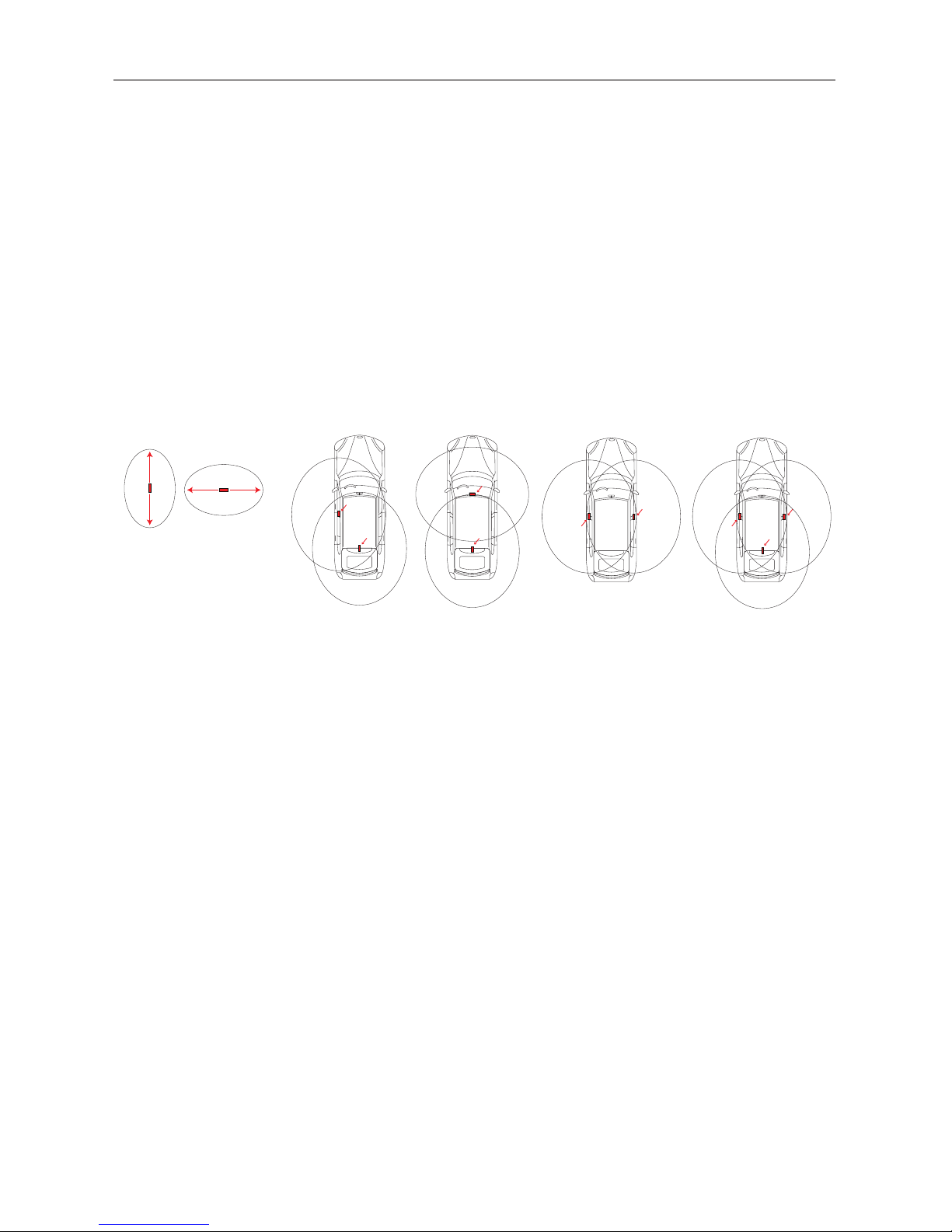
Antenna Mounting and Installation Points
In order to maximize range, the following antenna mounting options should be discussed with the customer to better suit their
needs.
Warning
• Do not directly mount the antenna on any metallic surface, this may significally decrease the range.
• To insure consistent operation, secure the antenna and make sure they will not move or dangle.
• Antennas are fragile, they can break easily. Make sure they are mounted on a solid (non flexible) part.
Recommended Antenna Mounting Locations
The recommended antenna mounting locations are for reference only. It is still required that you perform the actual range test
when installing the antenna to ensure that the range is satisfactory. You may require to relocate the antennas to different areas
around the recommended locations until maximum range is achieved.
Option 1
Option 2
Option 3
Antennas
Since this is a directional antenna,
range will be aected by antenna
placement/mounting
Horizontal rangeVertical range
Option 4
Note: An optionnal 12-foot antenna (part# SANT-PKE12) can be installed to increase the active zone coverage. When a
third antenna is installed, feature 4, option 2 must be enable through the "Features and Options List" section on page 21.
Vehicle Category Installation Specification
Sub Compact, Compact & Sedan:
For optimal performance, install the 18-foot antenna in the headliner or below the rear deck.
Note: Installation in the trunk will greatly affect and reduce range and overall system performance.
Minivan & SUV:
To maximize range in the rear of the vehicle, install the 18-foot antenna in the headliner.
Pickup (with cab) & Cargo:
To maximize range in the rear of the vehicle, install the 18-foot antenna in the bumper, behind the license plate.
Pickup (without cab):
Suggested Installation: Option 3. Antennas should be mounted on the driver and passenger side since the tailgate does not
require to be controlled.
Convertible:
Install 8-foot antenna in windshield pillar on driver side and the 18-feet antenna behind the rear seats.
Note: On vehicle with fiberglass bodies or convertibles, the range will be significantly increased.
Page 6

6
© 2012 Directed� All rights reserved�
Installation Type Selection
Choosing the right installation type according to the device you install.
Corresponding installation type according to what device you are installing Page
Type 1 - PKE Standalone
page 7
Type 2a - PKE + Xpresskit Bypass + AutoStart or AstroStart or Viper/Python/Clifford Directed
Remote Starter (with 4-pin antenna connector)
page 8
Type 2b - PKE + Xpresskit Bypass + Viper/Python/Clifford Directed Remote Starter (with 6-pin
antenna connector)
page 9
Type 3a - PKE + Xpresskit Bypass + DIRECTED SmartStart + Autostart or Astrostart Directed Remote
Starter (with 4-pin antenna connector)
page 10
Type 3b - PKE + Xpresskit Bypass + DIRECTED SmartStart + Viper/Python/Clifford Directed Remote
Starter (with 6-pin antenna connector)
page 11
Type 3c - PKE + Xpresskit Bypass + DIRECTED SmartStart + Viper/Python/Clifford Directed Remote
Starter (with 4-pin antenna connector)
page 12
Type 4 - PKE + 4x10/5x10 page 13
Type 5 - PKE + Xpresskit Bypass page 14
Type 6 - PKE + DIRECTED SmartStart + 4x10/5x10 page 15
Type 7 - PKE + Xpresskit Bypass - Remote Start Ready (RSR) + DIRECTED SmartStart page 16
Type 8 - PKE + Xpresskit Bypass - Range Extender (RXT) + XL202 page 17
Type 9 - PKE + AutoStart or AstroStart or Viper/Python/Clifford Directed Remote Starter (with 4pin
antenna connector)
page 18
Page 7
7
© 2012 Directed� All rights reserved�
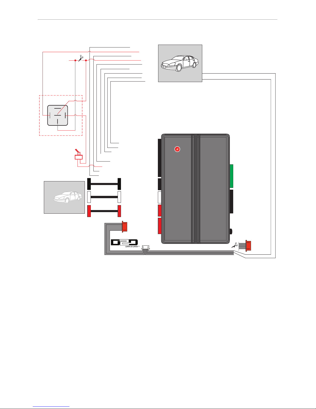
Installation diagram
Type 1 - PKE Standalone
6 Green 6 Black
4 Red2 Black
2 Black
2 Red10 Black
LED
PKE
Prog. Button
(-) Unlock Output: Blue: 2
(-) Lock Output: Green: 1
(+) Door Sense Input: White/Purple: 4**
(-) Starter Kill Output: White/Black: 6
(-) Parking Light Output: White/Pink: 7
(-) Door Sense Input: Blue/White: 10**
(-) Unlock
(-) Lock
(+) Brake
(+) Starter
(+) Ignition
(-) Parking Light
(-) Door Sense**
Antenna (8 feet)
Antenna (18 feet)
86 85
30
87a
87
(+) Brake Input: Purple/Black: 5
(+) Door Sense**
Starter Disable:
This connection is
optional and additional parts are
sold separately.
Refer to the
Antenna Location
and Installation Points
section on page 5 for
more information.
(-) Horn Output: Red/White: 3
(-) Horn
This toggle switch will
bypass the starter disable.
(-) Ground: Black: 2
RX: Blue: 1
(+) 12v: Red: 4
D2D Y CABLE
Cut the 4-wire red connector of D2D Y-cable and connect
12v and Ground wires to the corresponding wires of the DIRECTED SmartStart
TM
cable.
Not Used
Ground: Black
(+)12v: Red
Ground: Black
(+)12v: Red
*Sold separately.
**Door sense: The polarity of the door sense in the vehicle will determine which wire to connect
from the PKE to the DIRECTED Remote Starter.
2 White
Optional
Antenna (12 feet)*
(Part# SANT-PKE12)
Page 8
8
© 2012 Directed� All rights reserved�
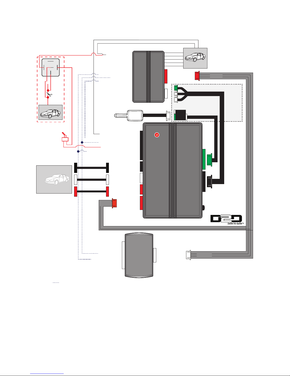
Type 2a - PKE + Xpresskit Bypass + AutoStart or AstroStart or Viper/Python/Clifford
Directed Remote Starter (with 4-pin antenna connector)
Note: 8210 Antenna Universal Adapter is required and sold separately.
These wires are not required in D2D mode.
4 Red
(-) Door Status Output
(+) Brake Output
(+) Brake Input: Purple/Black: 5
(-) Starter Kill: White/Black: 6
(-) Door Sense Input: Blue/White: 10***
(+) Brake Input
(-) Door Sense Input***
Remote
Starter*
8210 Main
Universal
Adaptor*:
Refer to the
8210 guide.
Regular Remote
Start Connections
To The Vehicle
4 White
(+) 12v: Red: 4
(-) Ground: Black: 2
RX: Green: 3
TX: Blue: 1
RX: Blue: 1
TX: Green: 3
(-) Ground: Black: 2
(+) 12v: Red: 4
(-) Ground: Black: 2
RX: Blue: 1
(+) 12v: Red: 4
Xpresskit
Interface Module*
D2D Y CABLE
6 Green 6 Black
4 Red2 Black 2 Red10 Black
LED
PKE
Prog. Button
Antenna**
8210*
Antenna Harness**
8210*
*Sold separately.
**Antenna & Antenna harness are sold with your Remote Starter kit.
*** Door sense: The polarity of the door sense in the vehicle will determine which wire to connect
from the PKE to the DIRECTED Remote Starter.
D2D Port
Antenna
D2D Port
(-) Horn Output: Red/White: 3
Antenna (8 feet)
Antenna (18 feet)
Refer to the
Antenna Location
and Installation Points
section on page 5 for
more information.
(+) Ignition Output
86 85
30
87a
87
(+) Starter Wire
4 wires red
connector
4 wires white
connector
3 wires red
connector
Starter Disable:
This connection is
optional and additional parts are
sold separately.
This toggle switch will
bypass the starter disable.
(+) Door Sense Input: White/Purple: 4***
(+) Door Sense Input***
2 White
Optional
Antenna (12 feet)*
(Part# SANT-PKE12)
Page 9

9
© 2012 Directed� All rights reserved�
Type 2b - PKE + Xpresskit Bypass + Viper/Python/Clifford Directed Remote Starter
(with 6-pin antenna connector)
These wires are not required in D2D mode.
4 Red
(-) Door Status Output
(+) Brake Output
(+) Brake Input: Purple/Black: 5
(-) Starter Kill: White/Black: 6
(-) Door Sense Input: Blue/White: 10****
(+) Brake Input
(+) Ignition Output
(-) Door Sense Input****
Remote
Starter*
4 White
(-) Ground: Black: 2
RX: Blue: 1
(+) 12v: Red: 4
Xpresskit
Interface Module*
(+) Door Sense Input: White/Purple: 4****
(+) Door Sense Input****
D2D Y CABLE
6 Green 6 Black
4 Red2 Black 2 Red10 Black
LED
PKE
Prog. Button
Antenna**
Antenna Harness**
*Sold separately.
**Antenna & Antenna harness are sold with your Remote Starter kit.
***10-foot Antenna Cable is included in the PKE kit.
**** Door sense: The polarity of the door sense in the vehicle will determine which wire to connect
from the PKE to the DIRECTED Remote Starter.
D2D Port
Antenna
10-foot Antenna Cable***
D2D Port
(+) 12v: Red: 4
(-) Ground: Black: 2
RX: Green: 3
TX: Blue: 1
RX: Blue: 1
TX: Green: 3
(-) Ground: Black: 2
(+) 12v: Red: 4
86 85
30
87a
87
(+) Starter Wire
Antenna (8 feet)
Antenna (18 feet)
Refer to the
Antenna Location
and Installation Points
section on page 5 for
more information.
Regular Remote
Start Connections
To The Vehicle
(-) Horn Output: Red/White: 3
4 wires red
connector
4 wires white
connector
3 wires red
connector
Starter Disable:
This connection is
optional and additional parts are
sold separately.
This toggle switch will
bypass the starter disable.
Optional
Antenna (12 feet)*
(Part# SANT-PKE12)
2 White
Page 10

10
© 2012 Directed� All rights reserved�
Type 3a - PKE + Xpresskit Bypass + DIRECTED SmartStart + Autostart or Astrostart
Directed Remote Starter (with 4-pin antenna connector)
Note: 8210 Antenna Universal Adapter is required and sold separately.
These wires are not required in D2D mode.
(-) Door Status Output
(+) Brake Output
(+) Brake Input: Purple/Black: 5
(-) Starter Kill: White/Black: 6
(-) Door Sense Input: Blue/White: 10****
(+) Brake Input
(-) Door Sense Input****
Regular Remote
Start Connections
To The Vehicle
4 White
(-) Ground: Black: 2
RX: Blue: 1
(+) 12v: Red: 4
Xpresskit
Interface Module*
(+) Door Sense Input: White/Purple: 4****
(+) Door Sense Input****
LED
CABLE***
6 Green 6 Black
4 Red
2 Black
2 Red10 Black
LED
PKE
Prog. Button
The connector depends
of the installed bypass.
Refer to the DIRECTED SmartStart
install guide for proper connection.
4 Red
Autostart RS*
Astrostart RS*
The remote starter model will
determine which connector to use.
Refer to the DIRECTED SmartStart
install guide for proper connection.
DIRECTED
SmartStart
TM
*
*Sold separately.
**Antenna & Antenna harness are sold with your Remote Starter kit.
***DIRECTED SmartStart
TM
cable is sold with your DIRECTED SmartStart
TM
system.
**** Door sense: The polarity of the door sense in the vehicle will determine which wire
to connect from the PKE to the DIRECTED Remote Starter.
D2D Port
Antenna
(+) 12v: Red: 4
(-) Ground: Black: 2
RX: Green: 3
TX: Blue: 1
RX: Blue: 1
TX: Green: 3
(-) Ground: Black: 2
(+) 12v: Red: 4
(-) Horn Output: Red/White: 3
Antenna (8 feet)
Antenna (18 feet)
Refer to the
Antenna Location
and Installation Points
section on page 5 for
more information.
D2D Y CABLE
Cut the 4-wire red connector of D2D Y-cable and connect RX (Blue),
12v and Ground wires to the corresponding wires of the DIRECTED SmartStart
TM
cable.
Not Used
RX: Blue
Ground: Black
(+)12v: Red
(+) Ignition Output
86 85
30
87a
87
(+) Starter Wire
Starter Disable:
This connection is
optional and additional parts are
sold separately.
3 wires red
connector
8210 Main
Universal
Adaptor*: Refer
to the 8210 guide.
Antenna**
8210*
Antenna Harness**
8210*
This toggle switch will
bypass the starter disable.
2 White
Optional
Antenna (12 feet)*
(Part# SANT-PKE12)
Page 11

11
© 2012 Directed� All rights reserved�
Type 3b - PKE + Xpresskit Bypass + DIRECTED SmartStart + Viper/Python/Clifford
Directed Remote Starter (with 6-pin antenna connector)
(+) Door Sense Input: White/Purple: 4****
(-) Starter Kill Output: White/Black: 6
(-) Door Sense Input: Blue/White: 10****
(+) Brake Input: Purple/Black: 5
(+) Brake
(-) Door Sense****
(+) Door Sense****
Antenna
RF Port
ESP Red
Connector
ESP Black
Connector
6 Green 6 Black
4 Red2 Black 2 Red10 Black
LED
PKE
Prog. Button
(-) Ground: Black: 2
(+) 12v: Red: 4
LED
(+)12v
TX
(-) Ground
RX
D2D Y CABLE
Antenna**
Antenna Harness**
10-foot Antenna Cable***
*Sold separately.
**Antenna, Antenna harness & DIRECTED SmartStart
TM
cable are sold with your Remote Starter kit.
***10-foot Antenna Cable is included in the PKE kit.
**** Door sense: The polarity of the door sense in the vehicle will determine which wire to connect
from the PKE to the DIRECTED Remote Starter.
(-) Horn Output: Red/White: 3
Antenna (8 feet)
Antenna (18 feet)
Refer to the
Antenna Location
and Installation Points
section on page 5 for
more information.
Connect these wires
to the vehicle.
DIRECTED
SmartStart
TM
*
3 wires red
connector
(+) Ignition Output
86 85
30
87a
87
(+) Starter Wire
Not Used
Starter Disable:
This connection is
optional and additional parts are
sold separately.
The remote starter model will
determine which connector to use.
Refer to the DIRECTED SmartStart
install guide for proper connection.
OR
This toggle switch will
bypass the starter disable.
D2D Red
Connector
4 White
Xpresskit
Interface Module*
(+) 12v: Red: 4
(-) Ground: Black: 2
RX: Green: 3
TX: Blue: 1
2 White
Optional
Antenna (12 feet)*
(Part# SANT-PKE12)
Page 12

12
© 2012 Directed� All rights reserved�
Type 3c - PKE + Xpresskit Bypass + DIRECTED SmartStart + Viper/Python/Clifford
Directed Remote Starter (with 4-pin antenna connector)
Note: 8210 Antenna Universal Adapter is required and sold separately.
(+) Door Sense Input: White/Purple: 4****
(-) Starter Kill Output: White/Black: 6
(-) Door Sense Input: Blue/White: 10****
(+) Brake Input: Purple/Black: 5
(+) Brake
(-) Door Sense****
(+) Door Sense****
Antenna
RF Port
ESP Red
Connector
ESP Black
Connector
6 Green 6 Black
4 Red
2 Black
2 Red10 Black
LED
PKE
Prog. Button
(-) Ground: Black: 2
(+) 12v: Red: 4
LED
(+)12v
TX
(-) Ground
RX
D2D Y CABLE
*Sold separately.
**Antenna, Antenna harness & DIRECTED SmartStart
TM
cable are sold with your Remote Starter kit.
***10-foot Antenna Cable is included in the PKE kit.
**** Door sense: The polarity of the door sense in the vehicle will determine which wire to connect
from the PKE to the DIRECTED Remote Starter.
(-) Horn Output: Red/White: 3
Antenna (8 feet)
Antenna (18 feet)
Refer to the
Antenna Location
and Installation Points
section on page 5 for
more information.
DIRECTED
SmartStart
TM
*
3 wires red
connector
(+) Ignition Output
86 85
30
87a
87
(+) Starter Wire
Not Used
Starter Disable:
This connection is
optional and additional parts are
sold separately.
The remote starter model will
determine which connector to use.
Refer to the DIRECTED SmartStart
install guide for proper connection.
OR
This toggle switch will
bypass the starter disable.
D2D Red
Connector
4 White
Xpresskit
Interface Module*
(+) 12v: Red: 4
(-) Ground: Black: 2
RX: Green: 3
TX: Blue: 1
Connect these wires
to the vehicle.
8210 Main
Universal
Adaptor*: Refer
to the 8210 guide.
Antenna**
8210*
Antenna Harness**
8210*
CABLE**
2 White
Optional
Antenna (12 feet)*
(Part# SANT-PKE12)
Page 13

13
© 2012 Directed� All rights reserved�
Type 4 - PKE + 4x10/5x10
RX: Blue: 1
(-) Ground: Black: 2
(+) 12v: Red: 4
(+) Door Sense Input: White/Purple: 4****
(-) Starter Kill Output: White/Black: 6
(-) Door Sense Input: Blue/White: 10****
(+) Brake Input: Purple/Black: 5
(+) Brake Input
(-) Door Sense Input****
(+) Door Sense Input****
These wires are not required in D2D mode.
6 Green 6 Black
4 Red2 Black 2 Red10 Black
LED
PKE
Prog. Button
Not Used
*
*Sold separately.
**Antenna & Antenna harness are sold with your Remote Starter kit.
***10-feet Antenna Cable is included in the PKE kit.
****Door sense: The polarity of the door sense in the vehicle will determine which wire to connect
from the PKE to the DIRECTED Remote Starter.
Antenna**
Antenna Harness**
D2D Port
Antenna
10-feet Antenna Cable***
D2D Y CABLE
(-) Horn Output: Red/White: 3
Antenna (8 feet)
Antenna (18 feet)
Refer to the
Antenna Location
and Installation Points
section on page 5 for
more information.
4 wires red
connector
3 wires red
connector
(+) Ignition Output
86 85
30
87a
87
(+) Starter Wire
Connect these wires
to the vehicle.
Starter Disable:
This connection is
optional and additional parts are
sold separately.
This toggle switch will
bypass the starter disable.
2 White
Optional
Antenna (12 feet)*
(Part# SANT-PKE12)
Page 14

14
© 2012 Directed� All rights reserved�
Type 5 - PKE + Xpresskit Bypass
Not Used
(+) Door Sense Input: White/Purple: 4**
(-) Starter Kill Output: White/Black: 6
(-) Door Sense Input: Blue/White: 10**
(+) Brake Output
(-) Door Sense Output**
(+) Brake Input: Purple/Black: 5
(+) Door Sense Output**
4 White
Xpresskit
Interface Module*
(-) Unlock Output: Blue: 2
(-) Lock Output: Green: 1
These wires are not required in D2D mode.
RX: Blue: 1
(-) Ground: Black: 2
TX: Green: 3
(+) 12v: Red: 4
6 Green 6 Black
4 Red2 Black 2 Red10 Black
LED
PKE
Prog. Button
RX: Blue: 1
TX: Green: 3
(-) Ground: Black: 2
(+) 12v: Red: 4
D2D Y CABLE
(-) Unlock Input
(-) Lock Input
(-) Parking Light Output: Pink/White: 7
*Sold separately.
**Door sense: The polarity of the door sense in the vehicle will determine which wire to connect
from the PKE to the DIRECTED Remote Starter.
D2D Port
(-) Horn Output: Red/White: 3
Antenna (8 feet)
Antenna (18 feet)
Refer to the
Antenna Location
and Installation Points
section on page 5 for
more information.
4 wires red
connector
3 wires red
connector
4 wires white
connector
86 85
30
87a
87
(+) Starter Wire
Connect these wires
to the vehicle.
(+) Ignition Output
Starter Disable:
This connection is
optional and additional parts are
sold separately.
This toggle switch will
bypass the starter disable.
2 White
Optional
Antenna (12 feet)*
(Part# SANT-PKE12)
Page 15

15
© 2012 Directed� All rights reserved�
Type 6 - PKE + DIRECTED SmartStart + 4x10/5x10
These wires are not required in D2D mode.
6 Green 6 Black
4 Red
2 Black
2 Red10 Black
LED
PKE
Prog. Button
CABLE**
TX: Blue: 1
RX: Green: 3
(-) Ground: Black: 2
(+) 12v: Red: 4
*Sold separately.
**DIRECTED SmartStart
TM
cable is sold with your DIRECTED SmartStartTM.
***Antenna & Antenna harness are sold with your Remote Starter kit.
****10-feet Antenna Cable is included in the PKE kit.
Note: Door sense: The polarity of the door sense in the vehicle will determine which wire to connect from the PKE to the DIRECTED Remote Starter.
*
(-) Ground: Black: 2
(+) 12v: Red: 4
RX: Blue: 1
LED
D2D Y CABLE
Cut the unused connectors of D2D Y cable and connect
RX (blue), 12v and Ground wires to the corresponding
wires of the D2D cable.
Not Used
RX: Blue
Ground: Black
(+)12v: Red
D2D Port
Antenna***
Antenna Harness***
10-feet Antenna Cable****
Antenna (8 feet)
Antenna (18 feet)
Refer to the
Antenna Location
and Installation Points
section on page 5 for
more information.
DIRECTED
SmartStart
TM
*
3 wires red
connector
(+) Door Sense Input: White/Purple: 4
(Door sense: See note)
(-) Starter Kill Output: White/Black: 6
(-) Door Sense Input: Blue/White: 10
(Door sense: See note)
(+) Brake Input
(-) Door Sense Input (See note)
(+) Brake Input: Purple/Black: 5
(+) Door Sense Input (See note)
(-) Horn Output: Red/White: 3
86 85
30
87a
87
(+) Starter Wire
Connect these wires
to the vehicle.
(+) Ignition Output
Starter Disable:
This connection is
optional and additional parts are
sold separately.
This toggle switch will
bypass the starter disable.
Not Used
(+)12v
TX
(-) Ground
RX
2 White
Optional
Antenna (12 feet)*
(Part# SANT-PKE12)
Page 16

16
© 2012 Directed� All rights reserved�
Type 7 - PKE + Xpresskit Bypass - Remote Start Ready (RSR) + DIRECTED SmartStart
(+) Door Sense Input: White/Purple: 4***
(-) Starter Kill Output: White/Black: 6
(-) Door Sense Input: Blue/White: 10***
(-) Ground: Black: 2
(+) 12v: Red: 4
(+) Brake Input: Purple/Black: 5
Remote Start ready
Xpresskit
Interface Module*
RX: Blue: 1
(+) Starter
(+) Ignition
86 85
30
87a
87
6 Green 6 Black
4 Red2 Black 2 Red10 Black
LED
PKE
Prog. Button
These wires are not required in D2D mode.
LED
D2D Y CABLE
Cut the unused connectors of D2D Y cable and connect
RX (blue), 12v and Ground wires to the corresponding
wires of the D2D cable.
Not Used
TX: Blue: 1
RX: Green: 3
(-) Ground: Black: 2
(+) 12v: Red: 4
(-) Unlock Output: Blue: 2
(-) Lock Output: Green: 1
(-) Parking Light Output: Pink/White: 7
*Sold separately.
**DIRECTED SmartStart
TM
cable is sold with your SmartStart system.
***Door sense: The polarity of the door sense in the vehicle will determine which wire to connect
from the PKE to the DIRECTED Remote Starter.
D2D Port
Antenna (8 feet)
Antenna (18 feet)
Refer to the
Antenna Location
and Installation Points
section on page 5 for
more information.
(-) Horn Output: Red/White: 3
DIRECTED
SmartStart
TM
*
Starter Disable:
This connection is optional
and additional parts are
sold separately.
3 wires red
connector
Connect these wires
to the vehicle.
See Remote Start Ready (RSR)
install guide according to your vehicle
for RSR connections details.
This toggle switch will
bypass the starter disable.
CABLE**
RX: Blue
Ground: Black
(+)12v: Red
(+)12v
TX
(-) Ground
RX
Not Used
2 White
Optional
Antenna (12 feet)*
(Part# SANT-PKE12)
Page 17

17
© 2012 Directed� All rights reserved�
Type 8 - PKE + Xpresskit Bypass - Range Extender (RXT) + XL202
Note: 8210 Antenna Universal Adapter is required and sold separately.
(+) Door Sense Input: White/Purple: 4***
(-) Starter Kill Output: White/Black: 6
(-) Door Sense Input: Blue/White: 10***
(-) Ground: Black: 2
(+) 12v: Red: 4
(+) Brake Input: Purple/Black: 5
RX: Blue: 1
86 85
30
87a
87
6 Green 6 Black
4 Red2 Black 2 Red10 Black
LED
PKE
Prog. Button
D2D Y CABLE
Cut the unused connectors of D2D Y
cable and connect 12v and Ground wires.
Not Used
Ground: Black
(+)12v: Red
(-) Parking Light Output: Pink/White: 7
*Sold separately.
**D2D XOVER Cable, Antenna and Antenna Harness are sold with your RF Kit.
***Door sense: The polarity of the door sense in the vehicle will determine which wire to connect
from the PKE to the DIRECTED Remote Starter.
XL202*
XL202: Range Extender
Antenna
D2D Port
Range Extender (RXT)
Xpresskit
Interface Module*
D2D Port
Antenna (8 feet)
Antenna (18 feet)
Refer to the
Antenna Location
and Installation Points
section on page 5 for
more information.
(-) Horn Output: Red/White: 3
3 wires red
connector
8210 Main
Universal
Adaptor*:
Refer to the
8210 guide.
Antenna**
8210*
Antenna Harness**
8210*
XOVER
**
Connect these wires
to the vehicle.
See Remote Start Ready (RSR)
install guide according to your vehicle
for RSR connections details.
(+) Starter
(+) Ignition
Starter Disable:
This connection is optional
and additional parts are
sold separately.
This toggle switch will
bypass the starter disable.
2 White
Optional
Antenna (12 feet)*
(Part# SANT-PKE12)
Page 18

18
© 2012 Directed� All rights reserved�
Type 9 - PKE + AutoStart or AstroStart or Viper/Python/Clifford Directed Remote Starter (with 4pin antenna connector)
Note: 8210 Antenna Universal Adapter is required and sold separately.
4 Red
(+) Brake Input: Purple/Black: 5
(-) Starter Kill: White/Black: 6
(-) Door Sense Input: Blue/White: 10***
(+) Brake Input
(-) Door Sense Input***
Remote
Starter*
8210 Main
Universal
Adaptor*:
Refer to the
8210 guide.
Regular Remote
Start Connections
To The Vehicle
6 Green 6 Black
4 Red
2 Black
2 Red10 Black
LED
PKE
Prog. Button
Antenna**
8210*
Antenna Harness**
8210*
*Sold separately.
**Antenna & Antenna harness are sold with your Remote Starter kit.
*** Door sense: The polarity of the door sense in the vehicle will determine which wire to connect
from the PKE to the DIRECTED Remote Starter.
D2D Port
Antenna
(-) Horn Output: Red/White: 3
Antenna (8 feet)
Antenna (18 feet)
Refer to the
Antenna Location
and Installation Points
section on page 5 for
more information.
(+) Ignition Output
86 85
30
87a
87
(+) Starter Wire
Starter Disable:
This connection is
optional and additional parts are
sold separately.
This toggle switch will
bypass the starter disable.
(+) Door Sense Input: White/Purple: 4***
(+) Door Sense Input***
2 White
Optional
Antenna (12 feet)*
(Part# SANT-PKE12)
Page 19

19
© 2012 Directed� All rights reserved�
Wiring connections
6 Green 6 Black
4 Red2 Black 2 Red10 Black
LED
PKE
Prog. Button
Antenna Port Remote Start
Antenna Port
D2D Port
Antenna 8-foot
Antenna 18-foot
Analog Port
2 White
Antenna 12-foot
(Optional)
Analog Port (H1), 10-pin white connector
H1/1 GREEN (-) LOCK OUTPUT
H1/2 BLUE (-) UNLOCK OUTPUT
H1/3 RED/WHITE (-) HORN OUTPUT
H1/4 WHITE/PURPLE (+) DOOR SENSE INPUT*
H1/5 PURPLE/BLACK (+) BRAKE INPUT
H1/6 WHITE/BLACK (-) STARTER KILL OUTPUT
H1/7 PINK/WHITE (-) PARKING LIGHTS OUTPUT
H1/8 PURPLE No connection
H1/9 PINK No connection
H1/10 BLUE/WHITE (-) DOOR SENSE INPUT*
* Only one of the Door sense input is required for proper operation.
D2D port (H2), 4-pin black connector
H2/1 BLUE RX
H2/2 BLACK (-) GROUND
H2/3 GREEN TX
H2/4 RED (+) 12V
Page 20

20
© 2012 Directed� All rights reserved�
Feature Programming
The feature programming can be done by following the instructions below.
Entering feature programming routine
To select a Feature, press and release the programming button the corresponding number of times according to the table
below, and then press and hold, the LED will flash to indicate the selected feature number.
To select this Feature number...
Press the programming button...
And the LED
will flashes...
Feature 1 Twice Once
Feature 2 3 times Twice
Feature 3 4 times 3 times
Feature 4 5 times 4 times
Feature 5 6 times 5 times
Feature 6 7 times 6 times
Changing feature options
Press the programming button the corresponding number of times according to the selected option. The LED will flash the
number of times according to the desired option. For example, if you select Option 3, you will press the programming button
3 times.
Accessing another feature
To change the option in another feature, wait 3 seconds after your last operation and the module will exit the menu programming. Repeat the steps in "Entering feature programming" and "Changing feature options" sections to select another feature
and option.
Exiting feature programming
No activity for 3 seconds.
Page 21

21
© 2012 Directed� All rights reserved�
Features and Options List
Features Options
1- RF Protocol Selection
1: Viper, Python, Clifford Supercode*
Directed new generation receiver technology
2: Viper, Python, Clifford Keeloq
Directed older generation receiver technology
3: AstroStart receiver technology
4: AS HDR - FM
AutoStart HDR (new style FM based) receiver technology
5: AS HDR - AM
AutoStart HDR (AM based) receiver technology
6: AS LDR - FM
AutoStart LDR (older style) receiver technology
2- Door Unlock Timing
1: 0�8 sec*
2: 0�4 sec
3: 3�5 sec
4: Double pulse (0�25 sec)
3: Door Lock Timing
1: 0�8 sec*
2: 0�4 sec
3: 3�5 sec
4: Double pulse (0�25 sec)
4: Number of Antenna
1: 2 Antennas (8ft - 18ft)*
2: 3 Antennas (8ft - 12 ft - 18 ft)
3: 1 Antenna (8ft)
5: Smart Lock**
1: 3 minutes timer*
2: 0 minutes timer (No delay)
3: 1 minute timer
4: 5 minutes timer
6: Door Open Interlock
1: ON*
The doors will lock as soon as the key fob leaves the zone even if a door is open�
2: OFF
The doors will not lock if the key fob leaves the zone while a door is open�
* Default option
** See SmartLock feature section for more details.
Page 22

22
© 2012 Directed� All rights reserved�
SmartLock feature
The purpose of the SmartLock feature is to prevent the doors from unwanted unlocking/locking when entering/exiting the
active zone multiple times for a pre-programmed delay (No delay*,1, 3 or 5 minutes). This is practical in situations such as
loading/unloading packages.
*SmartLock feature is disabled when it is set to no delay, which is confi gurable.
Note: If the Door Open Interlock feature is enabled, the SmartLock feature will not be able to lock a door when it is left opened.
For more information about using SmartLock feature, see owner's guide.
SmartLock feature diagram
1
2
3
FOB exits the zone: The doors lock, timer starts.
FOB re-enters the zone within the pre-programmed delay:
Doors unlock, timer is reset and stays frozen.
FOB exits the zone:
Doors stay unlocked, fresh timer re-starts.
4
FOB re-enters the zone within the pre-programmed delay:
Doors stay unlocked, timer is reset and stays frozen.
FOB exits the zone:
Doors stay unlocked, fresh timer re-starts.
The doors will automatically lock once the valid key fob remains
out of the active zone longer than the pre-programmed delay.
SmartLock feature CANCELLED.
SmartLock Feature ON
5
Step 3 & 4 will not
cause the doors to
lock/unlock as
long as the doors
are not opened/
closed during the
whole sequence.
Page 23

23
© 2012 Directed� All rights reserved�
Remote pairing
Important:
The antennas must be connected to the PKE module before proceeding to pairing mode.
RF Protocole Selection need to be done prior to pair the PKE to the remote starter. See "Feature Programming" section on
page 20.
Pairing the FOB to the PKE module:
1. Press and release, then press and hold the programming button on the PKE module. The LED will turn on solid indicating
that the PKE module is in pairing mode.
2. Release the programming button.
3. Quickly press and release then press and hold the remote
button.
4. The fob LED will flash red followed by a green flash to confirm the pairing was successful.
5. If more than 1 red LED flash occurs during the programming process, verify antenna connections and repeat the pairing
procedure.
Note: Press and release the programming button at any moment to exit remote pairing mode.
Pairing the PKE system to the remote starter module:
This step is necessary when a remote starter is installed prior to having a PKE system. This allows the remote starter to recognize commands from the PKE system. It is important that the FOB be paired to the PKE module first before proceeding with
this step.
1. Place the remote starter in remote pairing mode (see the remote starter instructions on remote pairing for more information).
2. Press and hold the programming button on the PKE. The LED will flash 3 times to confirm that data is being sent to the
remote starter.
3. Release the programming button. The remote starter will confirm the remote learning operation. Refer to the remote starter
installation guide for more information on remote pairing.
Factory reset
To execute a factory reset:
1. Disconnect the power supply from the PKE module.
2. Press and hold the programming button.
3. Reconnect the power supply to the module. The LED will flash 5 times quickly to confirm factory reset.
Diagnostics
LED Parking Lights
Flashing
rate
Event
Flashes x1 Flashes x 1 Slow Lock
Flashes x 2 Flashes x 2 Slow Unlock
Flashes x 3 Flashes x 3 Fast
Enabling PKE through FOB
(Standalone installation only)
Flashes x 3 Flashes x 3 Slow
Remote ID being sent to remote
starter
Flashes x 4 Flashes x 4 Slow PKE learned
Flashes x 5 Flashes x 5 Fast
Disabling PKE through FOB
(Standalone installation only)
Flashes x 5 Flashes x 5 Fast Factory reset
ON continuously N/A
ON continuously
PKE disabled
Page 24

N2102T 2012-07
Vista, CA 92081
www.directed.com
© 2012 Directed—All rights reserved
The company behind this system is Directed
Since its inception, Directed has had one purpose, to provide consumers
with the finest vehicle security and car stereo products and accessories avail-
able. The recipient of nearly 100 patents and Innovations Awards in the
field of advanced electronic technology.
Directed is ISO 9001 registered.
Quality Directed products are sold and serviced throughout North America
and around the world.
Call (800) 274-0200 for more information about our products and services.
Designed and Engineered in the USA
 Loading...