

Page 1
© 2005 Directed Electronics, Inc. 1 v2.1
VATS / PASSLOCK / TRANSPONDER
Universal Alarm Bypass Module
Model #s 20402 & 29402
This module lets you bypass virtually any type of factory passive
anti-theft system on the market today to remotely start your
vehicle without permanently disabling the vehicle’s anti-theft
system.
In 1983, General Motors came out with their first Vehicle AntiTheft System known as VATS which uses a resistor pellet in
the key. Since that time, other more sophisticated theft systems
have followed. Most of these theft systems are still resistance
based, and another uses a “Transponder” which is a tiny pellet
or chip embeded within the the head of the ignition key.
Contents:
1 Universal Alarm Bypass Module
1 8 position wire harness
1 Transponder loop w/connector
2 Cable Ties
1 Instruction booklet
2 Double-stick foam tape
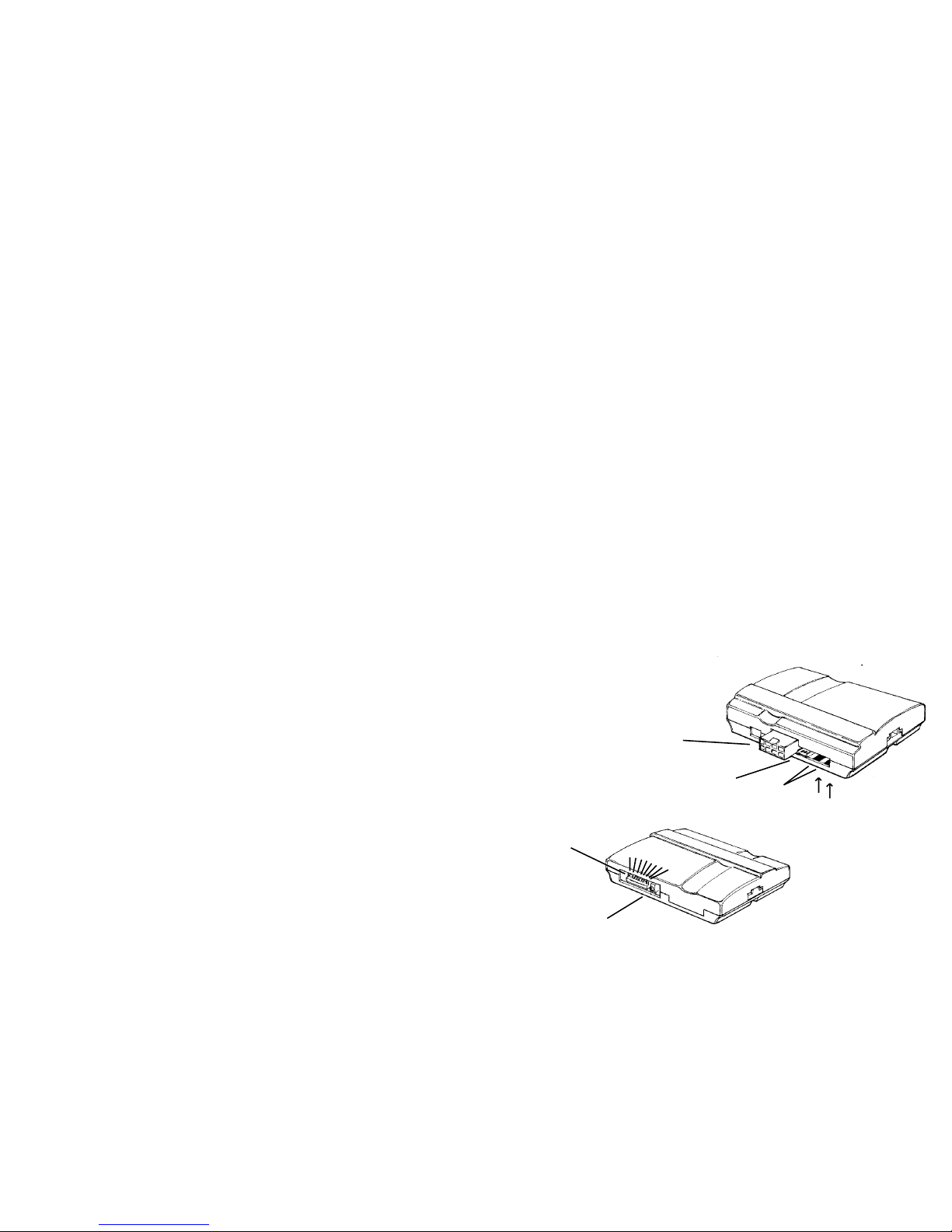
8 position harness
connector
Transponder Loop
connector
2 Resistor
Measuring Pads
8 position
dip-switch
Variable Resistor
FRONT VIEW
BACK VIEW
Up is OFF
Down is ON
12345678
Page 2

v2.1 2 © 2005 Directed Electronics, Inc. © 2005 Directed Electronics, Inc. 3 v2.1
Determine which type system you have in your vehicle. If unsure -
- follow the chart on the previous page to determine the system
you have. There are several types of systems as outlined below:
General Motors VATS and PASSLOCK 1 and PASSLOCK 2 theft
systems. For these, you will be required to dial-in a resistor value
which matches the one on your security system. The method is described on the following pages for each type system using the dip
switches and the variable resistor. The variable resistor is a 10 turn
potentiometer which can be dialed up from zero ohms to 1,000 ohms.
SATURN vehicles up to the 2000 model year simply hook up to
the Universal Alarm Bypass Module as shown on page 9. If you
have a 2000 model year or later Saturn vehicle, see page 10.
TRANSPONDER / PASSKEY 3 / P.A.T.S. systems require a
transponder (or extra key) to be used with our system. Follow the
directions on page 10 and 11.
List of vehicles and the types of security systems:
Acura 3.2TL 98+ Transponder
Audi A4,A6,A8 98+ Transponder
Acura CL 97+ Transponder
Acura Integra Transponder
Acura NSX Transponder
Acura RL 98+ Transponder
BMW (all 97 +) Transponder
Buick LeSabre 90 - 01 VATS
Buick Park Ave 91 - 96 VATS
Buick Park Ave 97+ Transponder
Buick Regal 93 -96 VATS
Buick Rendez Vous Transponder
Buick Riviera 93 -96 VATS
Buick Roadmaster 93 - 96 VATS
Buick Skylark 96-98 Passlock
Cadillac Allante VATS
Cadillac Brougham VATS
Cadillac Catera 97+ Transponder
Cadillac DeVille 92 - 98 VATS
Cadillac DeVille 99+ Transponder
Cadillac Eldorado 89 - 98 VATS
Cadillac Eldorado 99+ Transponder
Cadillac Escalade 00+ Passlock
Cadillac Fleetwood 90 - 96 VATS
Cadillac Seville 90 - 98 VATS
Cadillac Seville 99+ Transpond
Chevrolet Astro Van 98+ Passlock II
Chevrolet Avalanche 01 Passlock
Chevrolet Blazer 98+ Passlock II
Chevrolet Camaro 86 + VATS
Chevrolet Cavalier 96-99 Passlock
Chevrolet Cavalier 2000+ PasslockII
Chevrolet Corvette 88 + VATS
Chevrolet Express 97+ Passlock
Chevrolet Impala 2000+ Passlock II
Chevrolet Lumina 96 -99 VATS
Chevrolet Malibu 97 -01 Passlock II
Chevrolet Monte Carlo 96-99 VATS
Chevrolet Monte Carlo 00+ Passlock II
Chevrolet Pickup Full-size 98+ Passlock II
Chevrolet S-10 98+ Passlock II
Chevrolet Silverado HD 01 PasslockII
Chevrolet SSR 01 Passlock
Chevrolet Suburban 98+ Passlock II
Chevrolet Tahoe 98+ Passlock II
Chevrolet Trailblazer 01+ PasslockII
Chevrolet Van 98+ Passlock II
Chevrolet Venture 99+ Transponder
Chrysler Concorde 98+ Transponder
Chrysler LHS 99+ Transponder
Chrysler PT Cruiser 00+ Transponder
Chrysler Sebring Convertible 98+ Transponder
Daewoo Leganza Transponder
Dodge 300 M 99+ Transponder
Dodge Intrepid 98+ Transponder
Dodge Neon 00+ Transponder
Ford Contour 97 + Transponder
Ford Crown Victoria 98+ (optional) Transponder
Ford Excursion 01+ Transponder
Ford Expedition 97+ Transponder
Ford Explorer 98+ Transponder
Ford Focus 01+ Transponder
Ford Mustang 98+ Transponder
Ford Pick Up (optional) Transponder
Ford Ranger 99+(optional) Transponder
Ford Sport Trac 01 Transponder
Ford Taurus 96 + Transponder
Ford Windstar 2000 + Transponder
GMC Envoy 01+ Passlock II
GMC Jimmy 98+ Passlock II
GMC Safari 98+ Passlock II
GMC Denali 99+ Passlock II
GMC Sierra Passlock II
GMC Sonoma 98 + Passlock II
GMC Suburban 98+ Passlock II
GMC Yukon 98+ Passlock II
Honda Accord 98+ Transponder
Honda Odyssey 98+ Transponder
Honda Prelude 98+ Transponder
Honda S2000 Transponder
Infiniti I30 98+ Transponder
Infiniti Q45 98+ Transponder
Infiniti QX4 Transponder
Jaguar (all 98+) Transponder
Isuzu Hombre 98+ Passlock II
Jeep Grand Cherokee 99+ Transponder
Jeep Liberty Transponder
Jeep TJ (Wrangler) 99+ Transponder
Lexus (all 97+) Transponder
Lincoln Blackwood Transponder
Lincoln Continental 97+ Transponder
Lincoln LS 2000+ Transponder
Lincoln Mark VIII 97+ Transponder
Lincoln Navigator 97+ Transponder
Lincoln Town Car 97+ Transponder
Mazda Tribute Transponder
Mercedes (all 97+) Transponder
Mercury Cougar 99+ Transponder
Mercury Grand Marquis Transponder
Mercury Mountaineer 98 + Transponder
Mercury Mystique 97+ Transponder
Mercury Sable 96+ Transponder
Mini Cooper 02 Transponder
Mitsubishi Eclipse Transponder
Mitsubishi Galant Transponder
Nissan Frontier S/C Transponder
Nissan Maxima 98+ Transponder
Oldsmobile Achieva 95 Passlock I
Oldsmobile Achieva 96+ Passlock II
Oldsmobile Alero 99+ Passlock II
Oldsmobile Aurora VATS
Oldsmobile Bravada 98 Passlock II
Oldsmobile Cutlass 97+ Passlock II
Oldsmobile Eighty-Eight VATS
Oldsmobile Intrique 98+ Passlock II
Oldsmobile Ninty-Eight VATS
Oldsmobile Silhoutte 99 Transponder
Pontiac Aztek 01 Transponder
Pontiac Bonneville 89+ VATS
Pontiac Firebird 88+ VATS
Pontiac Grand Am 96 - 98 Passlock
Pontiac Grand Am 99+ Passlock II
Pontiac Grand Prix 92 – 96 VATS
Pontiac Grand Prix 97+ Transponder
Pontiac Montana 99+ Transponder
Pontiac Sunfire 96-99 Passlock I
Pontiac Sunfire 2000+ Passlock II
Porsche (all 97+) Transponder
Saab (all 97+) Transponder
Saturn 97-99 Factory Alarm
Saturn 00+ Transponder
Subaru Legacy 00+ Transponder
Subaru Outback 00+ Transponder
Toyota Avalon 98+ Transponder
Toyota Camry 98+ Transponder
Toyota Highlander 01+ Transponder
Toyota Land Cruiser 98+ Transponder
Toyota Solara 99 + Transponder
Toyota Supra 98+ Transponder
Volkswagen Beetle 98+ Transponder
Volkswagen Golf 98+ Transponder
Volkswagen Passat 98+ Transponder
Volvo (all 98+) Transponder
Page 3
v2.1 4 © 2005 Directed Electronics, Inc. © 2005 Directed Electronics, Inc. 5 v2.1
VATS:
Before performing this set up, make sure the vehicle will start with the
transmitter if you leave the ignition key in the key cylinder.
1. Put dip switch 1, 7 and 8 into the OFF (up) position
2. Measure the resistance of the key. It should be between 392 ohms and
11,800 ohms. To do this, put the ohm meter probes on each side of the
key pellet. This value should be close to one of the following (all values
in ohms): 392, 523, 681, 887, 1.13K, 1.47K, 1.87K, 3.01K, 3.74K, 4.75K,
6.04K, 7.5K, 9.53K, 11.8K.
3. Locate the closest value which is less than your desired value on the
chart on page 4. Set dip-switches 2 through 6 as shown on page 4.
4. Put your ohm meter (multi-meter) probes on the two silver resistance
measuring pads through the opening shown in the drawing -- making
good contact with these two silver pads on the board. (See drawing on
page 1). Or put your two probes into the two holes on the bottom of the
case making contact with the underside of the silver pads. Either contact point method will work.
5. With the probes held firmly, finish reaching the final resistance value
needed for your system by turning the screw on the variable resistor on
the side of the unit next to the dip switches. Turn the screw until the
resistance value matches the resistance value of the key.
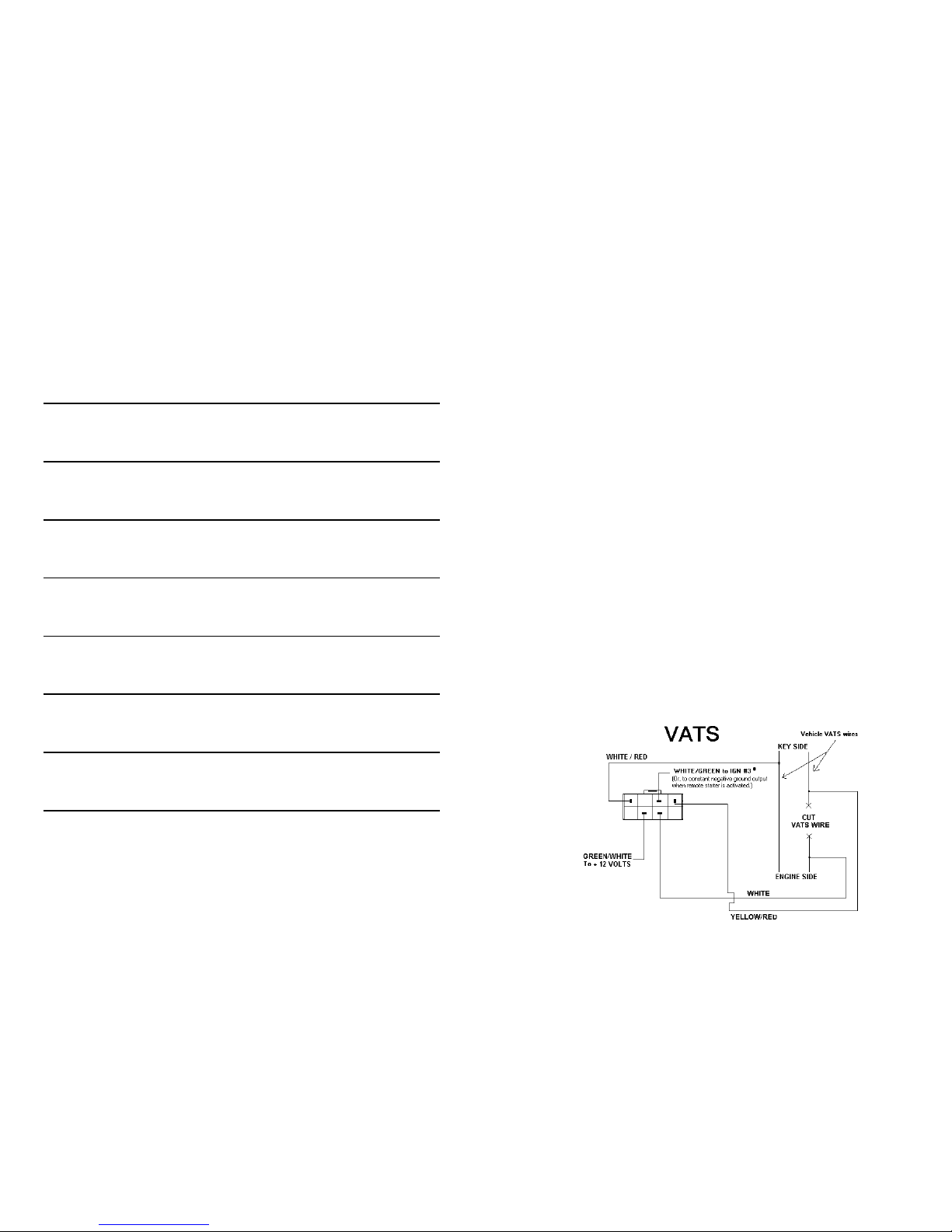
6. Locate the pair of VATS wires (sometimes White/Black striped and
Purple/Black striped). These wires are often in a plastic tube. Be careful not to cut into the Yellow Air Bag wires! The Air Bag wires are often in
a yellow plastic tube that is clearly marked. The VATS wires run from
the ignition switch down the column under the dash. Connect the Universal Alarm Bypass Module using the diagram below.
Dip Switch #1 Off
Dip Switch #7 Off
Dip Switch #8 Off
*See page 12 if you do not have an IGN3 wire on your remote
starter
Dip Switch # 2 3 4 5 6
Resistor Value 0.825 1.65 3.32 6.65 13.3 Final Resistance (k ohms)
ON ON ON ON ON 0.000 +Variable Resistor Value
OFF ON ON ON ON 0.825 +Variable Resistor Value
ON OFF ON ON ON 1.650 +Variable Resistor Value
OFF OFF ON ON ON 2.475 +Variable Resistor Value
ON ON OFF ON ON 3.320 +Variable Resistor Value
OFF ON OFF ON ON 4.145 +Variable Resistor Value
ON OFF OFF ON ON 4.970 +Variable Resistor Value
OFF OFF OFF ON ON 5.795 +Variable Resistor Value
ON ON ON OFF ON 6.650 +Variable Resistor Value
OFF ON ON OFF ON 7.475 +Variable Resistor Value
ON OFF ON OFF ON 8.300 +Variable Resistor Value
OFF OFF ON OFF ON 9.125 +Variable Resistor Value
ON ON OFF OFF ON 9.970 +Variable Resistor Value
OFF ON OFF OFF ON 10.795 +Variable Resistor Value
ON OFF OFF OFF ON 11.620 +Variable Resistor Value
OFF OFF OFF OFF ON 12.445 +Variable Resistor Value
ON ON ON ON OFF 13.300 +Variable Resistor Value
OFF ON ON ON OFF 14.125 +Variable Resistor Value
ON OFF ON ON OFF 14.950 +Variable Resistor Value
OFF OFF ON ON OFF 15.775 +Variable Resistor Value
ON ON OFF ON OFF 16.620 +Variable Resistor Value
OFF ON OFF ON OFF 17.445 +Variable Resistor Value
ON OFF OFF ON OFF 18.270 +Variable Resistor Value
OFF OFF OFF ON OFF 19.095 +Variable Resistor Value
ON ON ON OFF OFF 19.950 +Variable Resistor Value
OFF ON ON OFF OFF 20.775 +Variable Resistor Value
ON OFF ON OFF OFF 21.600 +Variable Resistor Value
OFF OFF ON OFF OFF 22.425 +Variable Resistor Value
ON ON OFF OFF OFF 23.270 +Variable Resistor Value
OFF ON OFF OFF OFF 24.095 +Variable Resistor Value
ON OFF OFF OFF OFF 24.920 +Variable Resistor Value
OFF OFF OFF OFF OFF 25.745 +Variable Resistor Value
DipSwitch #1 Dip Switch #7 Dip Switch #8
VATS OFF OFF OFF
PASSLOCK 1 ON ON OFF
PASSLOCK 2 OFF OFF OFF
Use this chart with VATS, PASSLOCK 1 and PASSLOCK 2.
All resistor values shown are in ‘K-ohms’ -- or 1,000 ohms. Thus
the 1.650 value shown in the third row is 1,650 ohms or 1.65 K ohms.
Page 4

v2.1 6 © 2005 Directed Electronics, Inc. © 2005 Directed Electronics, Inc. 7 v2.1
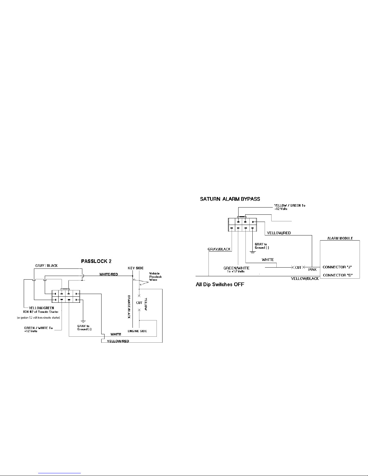
PASSLOCK 2:
1. Turn dip switches 1, 7, and 8 to the OFF (up) position.
2. Remove the bottom half of the steering column shroud.
3. Locate the small three wire harness (with Red/White, Yellow and Or-
ange/Black wires on trucks and White, Yellow and Black on cars)
that come off the ignition lock cylinder. These are usually the smallest
wires.
4. Cut the Yellow wire in half and strip back both ends. Remove the
insulation on the Orange/Black wire (trucks) or the Black wire (cars)
without cutting the wire. The Red/White or White wire is not used.
5. Turn the key to the “Run” position and place the vehicle in Reverse.
6. Connect the key side of the Yellow wire to the + positive lead of your
digital meter and the Black wire (cars) or Orange/Black wire (trucks)
to the - negative lead of your digital meter.
7. Turn the ignition key to the “START” position and release it. Denote
the resistance reading as this will be the resistance that will need to be
PASSLOCK 1:
1. Put dip switches 1 and 7 in the ON (down) position and dip switch 8 in
the OFF (up) position.
2. Remove the bottom half of the steering column shroud.
3. Locate the small three wire harness (with White, Black and Yellow
wires) running down from the ignition key cylinder on the top right hand
side of the steering column into the instrument panel. These wires are
usually the smallest wires in the harness.
4. Cut the Yellow wire in half and strip back both ends. Remove some of
the insulation on the Black wire without cutting the wire. The White
wire is not used.
5. Turn the ignition key to the “ON” or “RUN” position and place the vehicle
into reverse.
6. With the ignition key still in and turned to the “RUN” position, measure
the resistance between the key side of the Yellow wire (connected to
the + positive lead of your digital meter) and the Black wire (connected
to the - negative side of your digital meter).
7. Turn the ignition key to the “START” position and release it. Denote
the resistance reading as this will be the resistance that will need to be
duplicated. Repeat this step several times to verify that you have a
consistent reading.
8. When you have identified the correct resistance use the chart on page 4
to set the resistance on the bypass module.
Locate the closest value
which is less than your desired value. Set dip-switches 2 through 6 to
match the chart on page 4 for this value.
9. Put your ohm meter (multi-meter) probes on the two silver resistance
measuring pads through the opening shown in the drawing -- making
good contact with these two silver pads on the board. (See drawing on
page 1). Or put your two probes into the two holes on the bottom of the
case making contact with the underside of the silver pads. Either contact point method will work.
10. With the probes held firmly -- dial-in the final resistance value needed
for your system by turning the screw on the variable resistor on the side
of the unit next to the dip switches. Turn the screw until the resistance
value matches the resistance value of the key.
11. Locate the Black “Bulb Test” wire on the left side of the steering column
in cavity “D” or “E” of the Black 5-way connector, just above the main
ignition switch connector. This is a different wire than the Black wire
mentioned in the above steps.
12. Connect the bypass module using the diagram below. Be sure to tape
over any connections to not leave any exposed wires.
*See page 12 if you do not have an IGN3 wire
PASSLOCK 1
To verify the Passlock 1 installation has the correct resistance
value and that the installation is correct -- hold the WHITE/
GREEN wire to ground and start the vehicle with the key . If the
vehicle starts and stays running - the installation is correct.
WHITE/GREEN to WHITE/
BLACK Ignition 3 wire from
the remote starter.*
Page 5
v2.1 8 © 2005 Directed Electronics, Inc. © 2005 Directed Electronics, Inc. 9 v2.1
SATURN:
Saturn vehicles up to the 2000 model year with factory
keyless entry have a unique bypass.
1. Set all dip switches to the OFF (up) position.
2. Locate the Alarm Module behind the right rear quarter trim
panel (trunk area). Connect the Pink and Yellow/Black
wires of Connector J and D of the alarm module as shown.
3. Cut the Pink wire in half and connect as shown.
*See page 12 if you do not have an IGN3 wire
Dip Switch #1 Off
Dip Switch #7 Off
Dip Switch #8 Off
*See page 12 if you do not have an IGN3 wire
Dip Switch #1 Off
Dip Switch #7 Off
Dip Switch #8 Off
duplicated. Repeat this step several times to verify that you have a
consistent reading.
8. When you have identified the correct resistance use the chart on page
4 to set the resistance on the bypass module. Locate the closest value
which is less than your desired value. Set dip-switches 2 through 6 to
match the chart on page 4 with this value.
9. Put your ohm meter (multi-meter) probes on the two silver resistance
measuring pads through the opening shown in the drawing -- making
good contact with these two silver pads on the board. (See drawing on
page 1). Or put your two probes into the two holes on the bottom of the
case making contact with the underside of the silver pads. Either contact point method will work.
10. With the probes held firmly -- dial-in the final resistance value needed
for your system by turning the screw on the variable resistor on the
side of the unit next to the dip switches. Turn the screw until the resistance value matches the resistance value of the key.
11. Connect the bypass module using the diagram on the next page. Be
sure to tape over any connections to not leave any exposed wires.
To verify that this installation is correct -- hold the WHITE/GREEN wire
and the GRA Y/BLA CK wire to ground and start the vehicle with the key.
If the vehicle starts and stays running - the installation is correct.
WHITE/GREEN TO WHITE/BLACK
IGN 3 output from car starter (or
to constant negative ground
output when remote starter is
WHITE/GREEN TO WHITE/BLACK
IGN 3 output from car starter (or to
constant negative ground output
when remote starter is activated).*
Page 6

v2.1 10 © 2005 Directed Electronics, Inc. © 2005 Directed Electronics, Inc. 11 v2.1
4. The transponder LOOP goes underneath the steering column and up toward the ignition key cylinder and needs to
be positioned so that there are 2 turns around the ignition
key cylinder as shown below. Transponder systems often
have a black plastic ring around the ignition lock switch.
This is the vehicle’s transponder pick-up antenna. It is important that the two loops of the Bypass Module be mounted
on or as close to this black plastic ring as possible. Slide
the tube up toward the ignition switch to tighten up the loops
of wire. Tape in place to hold. Plug the other end of the
transponder loop into the Universal Alarm Bypass Module.
5. Now start the vehicle with the remote starter. If the vehicle
starts and runs for at least 30 seconds the transponder bypass is correct. Note: If the vehicle does not start with the
remote starter, try adjusting or changing the position of the
transponder in the Bypass Module or adjusting the position
of the two loop wire around the transponder pick-up antenna mentioned above.
Note: The key that the transponder was removed from will no
longer start the vehicle.
TRANSPONDER / PASSKEY 3 / P.A.T.S.:
‘Smart Key’ & other Transponder systems
Note: For this type of security system - you must sacrifice one of
the spare keys that comes with the car. This key will be used
for the transponder. The dealership can progam a spare key,
but make sure they program all keys to the vehicle since
learning just one transponder could erase all other key transponders (including the key used for the Bypass Module).
1. Set all dip switches on the bypass module to the OFF (up)
position.
2. Remove the transponder from the key (there maybe a door
on the top of the key that can be opened and the transponder can be removed). Or, the entire key may be mounted
inside the Bypass Module. Be sure to cut the key in half or
grind off some of the teeth to render it unusable.
3. Pull apart the case and place the transponder, or the head of
the key, inside the 10 wire loop on the circuit board. Transponders are directional and must be placed along the same
direction that the key would lay. Use the double stick foam
tape provided -- one layer on the circuit board and then the
transponder, or key, and finally the second double-stick foam
tape layer on top of it to hold key securly in place.
Place Key with Transponder inside case on pc
board as shown. Use double stick tape to hold
to the key in place.
○○○○○○○○○○○○○○
Page 7

v2.1 12 © 2005 Directed Electronics, Inc. © 2005 Directed Electronics, Inc. 13 v2.1
For Car Starters that do not have an Ignition 3
output: You will need an Ignition 3 output from your remote
car starter for all of the hookups shown on the preceding pages.
Most models of remote starters use the WHITE/BLACK wire in
the control harness as the Ignition 3 output. If you ha ve a brand
of remote car starter that does not have an Ignition 3 output -or, if you ha ve an AutoCommand model 25522 which does not
have an Ignition 3 output -- f ollow the relay hook-up belo w using
Bosch type 30 Amp relays for creating the Ignition 3 output.
Ignition 3 output to control
alarm bypass module
limited lifetime consumer warranty
Directed Electronics, Inc. (hereinafter “Directed”) promises to the original purchaser to
repair or replace with a comparable reconditioned Directed alarm bypass unit if this Directed
alarm bypass unit (hereinafter “Unit”), excluding without limitation, any remote transmitters
or associated accessories, proves defective in materials or workmanship under normal use for
the life of the vehicle which the Unit is originally installed. During this period, so long as the
Unit remained installed in the original vehicle, Directed will at its option, repair or replace
this Unit if it is proved defective in workmanship or material PROVIDED the Unit is
returned to Directed’s warranty department at One Viper Way, Vista, CA 92081, along with
$20 postage and handling fee, a bill of sale or other dated proof of purchase bearing the
following information: Date of purchase, name and location of the merchant who sold the
Unit, and product description. This warranty does not cover labor costs for the removal or
reinstallation of the Unit. This warranty is non-transferable and does not apply to any Unit
that has been modified or used in a manner contrary to its intended purpose, and this
warranty does not cover damage to any Unit caused by installation or removal of the Unit.
This warranty is void if the Unit has been damaged by accident or unreasonable use, neglect,
improper service or other causes not arising out of defects in materials or workmanship.
Directed makes no warranty against theft of a vehicle or its contents.
THE FOREGOING WARRANTY IS THE EXCLUSIVE PRODUCT WARRANTY,
OTHERWISE, ALL WARRANTIES INCLUDING BUT NOT LIMITED TO EXPRESS
WARRANTY, IMPLIED WARRANTY, WARRANTY OF MERCHANTABILITY, OR
FITNESS FOR A PARTICULAR PURPOSE ARE EXPRESSLY EXCLUDED AND
DISCLAIMED TO THE MAXIMUM EXTENT ALLOWED BY LAW, AND
DIRECTED NEITHER ASSUMES NOR AUTHORIZES ANY PERSON TO ASSUME
FOR IT ANY LIABILITY IN CONNECTION WITH THE SALE OF THE PRODUCT.
DIRECTED HAS ABSOLUTELY NO LIABILITY FOR ANY AND ALL ACTS OF
THIRD PARTIES INCLUDING ITS AUTHORIZED DEALERS OR INSTALLERS.
SOME STATES DO NOT ALLOW THE LIMITATION ON HOW LONG AN
IMPLIED WARRANTY LASTS, SO THE ABOVE LIMITATION MAY NOT APPLY TO
YOU.
LIMITATION OF DAMAGES AND LIABILITY. CONSUMER’S REMEDY IS
LIMITED TO REPAIR OR REPLACEMENT OF THE UNIT, AND IN NO EVENT
SHALL DIRECTED’S LIABILITY EXCEED THE PURCHASE PRICE OF THE UNIT.
IN ANY EVENT, DIRECTED SHALL NOT BE LIABLE FOR ANY DAMAGES
INCLUDING, BUT NOT LIMITED TO, ANY DIRECT, INDIRECT, INCIDENTAL,
SPECIAL, PUNITIVE OR CONSEQUENTIAL DAMAGES, LOST PROFITS, LOST
SAVINGS, OR, TO THE EXTENT ALLOWED BY APPLICABLE LAW, DAMAGES
RESULTING FROM DEATH OR INJURY ARISING OUT OF
OR IN CONNECTION
WITH THE INSTALLATION, USE, IMPROPER USE, OR INABILITY TO USE, THE
PRODUCT, EVEN IF THE PARTY HAS BEEN ADVISED OF THE POSSIBILITY OF
SUCH DAMAGES. SOME STATES DO NOT ALLOW THE EXCLUSION OF
LIMITATION OF INCIDENTAL OR CONSEQUENTIAL DAMAGES, SO THE
ABOVE LIMITATIONS OR EXCLUSION MAY NOT APPLY TO YOU. THE
CONSUMER AGREES AND CONSENTS THAT ALL DISPUTES BETWEEN THE
CONSUMER AND DIRECTED SHALL BE RESOLVED IN ACCORDANCE WITH
CALIFORNIA LAWS IN SAN DIEGO COUNTY, CALIFORNIA.
Page 8

v2.1 14 © 2005 Directed Electronics, Inc. 15 v2.1
IMPORTANT NOTE:
This product warranty is automatically void if its date code or serial number is defaced,
missing, or altered.
Make sure you have all of the following information from your dealer:
A clear copy of the sales receipt, showing the following:
➤
Date of purchase
➤ Authorized dealer’s company name and address
➤ Item number
The company behind this system is Directed Electronics, Inc.
Since its inception, Directed Electronics has had one purpose, to provide consumers with the
finest vehicle security and car stereo products and accessories available. The recipient of
nearly 100 patents and Innovations Awards in the field of advanced electronic technology,
DIRECTED is ISO 9001 registered.
Quality Directed Electronics products are sold and serviced throughout North America and
around the world.
Call (800) 876-0800 for more information about our products and services.
Directed Electronics is committed to delivering world class quality products
and services that excite and delight our customers.
Directed Electronics, Inc.
Vista, CA 92081
www.designtech-intl.com
www.directed.com
© 2005 Directed Electronics, Inc. – All rights reserved
06-05
 Loading...