

Page 1
Platform: DBALL2
Firmware TL6:
Update Alert: Firmware updates are posted the web on a regular basis. We recommendon
that you check for firmware and/or install guide updates prior to installing this product.
Installation Guide
The 6 firmware for 2 is an all-in-one door lock and override module compatible withTL DBALL specific
Toyota and Lexus vehicles.
This module can only be flashed and configured using Xpress at www.directechs.com orVIP
using the Directechs Mobile application for smartphones. Refer to
section 23on page
WARNING
- No takeover feature is available.
- To remote start the engine, the hood, hatch, and all doors must be closed.
for more information.
Important:
This guide is compatible with the firmware .TL6 version 1.36 and higher
the Module Programming
Rev.: 20 708115
Index
Vehicle Application Guide ....... .................. .................................. ............................... ....................................................
OEM Remote Starter Detection....................................................................................................................................
Installation s s(Wiring Diagram & Vehicle Wiring Reference Chart )
Type 1........................................ ....................................................................................................................................
Type 2........................................ ....................................................................................................................................
Type 3........................................ ....................................................................................................................................
Type 4........................................ ....................................................................................................................................
Type 5........................................ ....................................................................................................................................
Type ........................................ ...........................................................................................................6 .........................
Type 7........................................ ....................................................................................................................................
Type 8........................................ ....................................................................................................................................
Programming
Module Programming.............. .......................................................................................................... ............................
Module Reset & Hard Reset..........................................................................................................................................
Feature & Options List. .................................................................................................................... ............................
Feature ....................................................................................................................Programming.. ............................
LED Diagnostics ..................................................................................................................& Troubleshooting. ..........
Limited One-Year Consumer Warranty..........................................................................................................................
Quick Reference Guide....................... ..........................................................................................................................
02
03
05
07
09
11
14
16
19
21
23
24
25
25
26
28
29
® Toyota Lexus are registered trademarks and property of .and their respective companies
© 201 Directed.7 All rights reserved.
Page 2
Platform: DBALL2
Vehicles
2017
2016
2015
2014
2013
2012
PK-I mmobilizer Byp as s-D ata No Key Req'd
DL-Arm Factory Security
DL-Disar m Fac tory Security
DL-Door Lock Control
DL-Door Unlock
DL-Driver Priority Unlock
DL-Tr unk / Hatch Release
FOB-Control of aftermarket alarm with OEM
remote
RS-SmartStart
RS-Tac h / RPM Output
SS-Entry Monitoring ALL Door Pins
SS-Entry Monitoring Hood Pin
SS-Entry Monitoring Trunk/Hatch Pin
SS-Factory Alarm T rigger Monitoring
ST-Brak e Status ( foot brak e)
ST-Door Lock s Status
ST-E-Brake Status
ST-Ignition Status
Lexus
ES 300h (Smart Key) 3 3 3 • • • • • • • D D ••••D•D••
ES350(SmartKey) 111 •••••••DD••••D•D••
GS350(SmartKey) 8222 • • • • • • • D D ••••D•D••
GS450h(SmartKey) 222 •••••••DD••••D•D••
Toyota
Avalon(SmartKey) 6444 • • • • • • • D D ••••D•D••
AvalonHybrid 6444 • • • • • • • D D ••••D•D••
Camry(SmartKey) 664444 • • • • • • • D D ••••D•D••
CamryHybrid 664444 • • • • • • • D D ••••D•D••
Corolla(SmartKey) 6555 • • • • • • • D D ••••D•D••
Priusc(SmartKey) 444•••••••DD••••D•D••
RAV4(SmartKey) 66444 • • • • • • • D D ••••D•D••
RAV4Hybrid 77 •••••••DD••••D•D••
Note s:
• Key les s and Smart Key will remain functional during remote start.
* By default, the tach is set to 1000 rpm on hybrid vehicles.
Legend:
PK: Transponder & Immobilizer Override
D: Data-to-Data (D2D) only
DL: OE Door Lock & Alarm Controls • : D2D & W ire-to-Wire (W 2W)
FOB: Sync CAN Interface w/ FOB Remote
RS: Remot e St art & Engine Controls
SS: Integrated Securit y & Monitoring
ST: Funct ion/Feature Status
If the vehicle is already equipped wit h an OE M remot e s tarter, t he inst aller must
disc onnect it before ins talling t he DBALL otherwise it will not program. See how to
know if t he vehicle is equipped with an OEM Remote starter on the nex t page.
Firmware TL6:
Rev.: 20 708115
Page 2
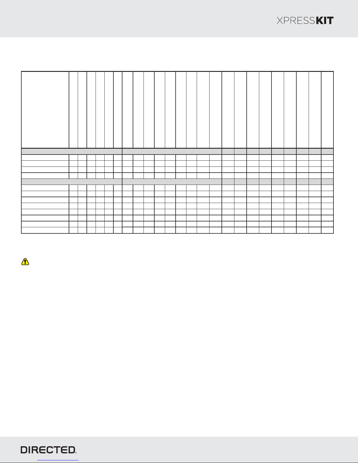
Vehicle Application Guide
The following table lists the vehicles and features which are compatible with this product. The number assigned to each year
allows you to determine which installation type should be used for your vehicle.
© 201 Directed.7 All rights reserved.
Page 3
Platform: DBALL2
Firmware TL6:
How to Know if the Vehicle is Equipped with an Remote StarterOEM
Rev.: 20 708115
Page 3
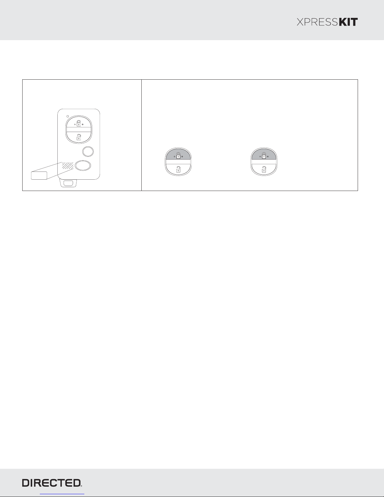
1- An “ ”ENGINE STARTER
sticker should be on the remote.
2- Remote start the remote starter:OEM
Press the remote control’s lock button twice within 2 seconds,
then press and hold the lock button for 3 seconds.
The parking lights flash after 3 seconds. The engine starts and
the parking lights flash repeatedly for 20 seconds.
Press & Hold
x2 &
ENGINE
STARTER
Important Remote Starter InformationOEM
If the vehicle is equipped with a physical add-on Lexus/Toyota OEM Remote Starter:
The factory remote starter must be permanently disconnected before programming the Directed interface as both
modules cannot coexist. See locating the OEM Remote Start on .the next page
for 3 seconds
If the vehicle is equipped with a BCM enabled Lexus/Toyota OEM Remote Starter:
The vehicle does not have a physical remote starter and only one module can be programed at a time. In this case
temporally disable the OEM remote start system using the following process:
1. Remove the fuse powering the OEM Remote Starter.
See locating the fuse powering the OEM Remote Starter on .the next page
2. Perform a module reset, see .« » sectionModule Reset
3. Perform the Module Programming steps ., see « » sectionModule Programming
After progra ming is successful replace the fuse powering the OEM Remote Starter.m
© 201 Directed.7 All rights reserved.
Page 4
Platform: DBALL2
Make Model Fuse Location Fuse Name Fuse Value
Lexus ES 300h (Smart Ke y) Engine room re l ay box , left side of e ngine compartment. Mayday 5A
Lexus ES 350 (Smart Key) Engine room relay box, lef t side of engine compartment. Mayday 5A
Lexus GS 350 (Smart Ke y) Engine room relay box, right side of engine compartment. DCM 7.5A
Lexus GS 450h (Smart Key) Bottom of l uggage room junction box , le f t rear quarter panel. DCM 7.5A
Make Model OEM Remote Start Location
Toyota Avalon (Smart Key) Behind glove box upper ri ght hand side.
Toyota Avalon Hybrid Behind glov e box upper ri ght hand side.
Toyota Camry (Smart Key)
Behi nd glove box upper lef t hand side.
Toyota Camry Hybrid
Behi nd glove box upper lef t hand side.
Toyota RAV4 ( Smart Key)
High above drivers kick panel.
Firmware TL6:
OEM Remote Start Fuse Location
Rev.: 20 708115
Page 4
Physical OEM Remote Start Location
© 201 Directed.7 All rights reserved.
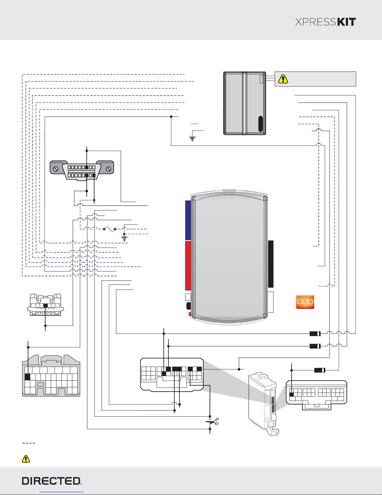
Page 5
Platform: DBALL2
Firmware TL6:
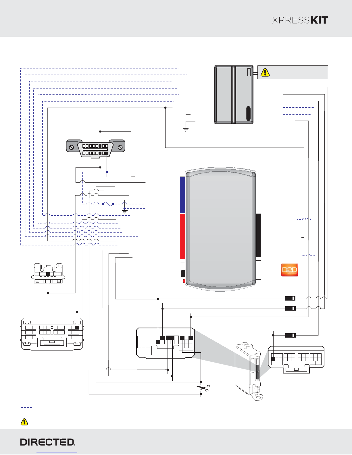
Installation Type 1
Rev.: 20 708115
Page 5
Steering Lock
(black onnector)7-pin c
5
7
6
4
(-) SLP:
Pink, pin 4
Diagnostic Connector OBD II
(connector side view)
HS CA N High:
Blue, pin 6
18
HS CA N Low:
3
12
169
(+) :12V
pin 14White,
Blue, pin 16
HS CA N High: 3Tan/Black:
Autolight Interrupt (conn. side): 8Yellow:
Autolight Interrupt (veh. side): 9Orange/Yellow:
Fuse 7.5A
(-) Output:SLP 11Yellow :/Red
(-) Ground: 12Brown :/Red
(-) E-Brake :Status
(-) Push-to-Start Output: Green/Black: 2
(-) Door Status Output: Green/White: 3
(-) Trunk Status Output: Red/Black: 4
[1] ( ) Tach Output: 5AC Violet/White:
(+) Ignition Status Output: Gray/Black: 7
(-) Hood Status Output: 9Violet/Brown:
(+) Brake Output: Gray: 6
Immo Data 1: Yellow/Black: 10
Immo Data 2: Orange/Black: 11
(-) Lock Output: Blue/Red: 12
HS CA N Low: 4Tan:
(+) 12V :Input 13Red:
(-) Ground: 14Black:
Black/White: 1
(-) Hood Status Input
(+) Brake Input
[]1 ( ) T Status InputAC ach
(-) Trunk Status Input
(-) Door Status Input
(-) E-Brake Status Input
(+) Ignition Input/Output
(+) 12V Input(+) 12V
(-) Ground
14
12
2
RF
Prog utton. B
LED
Remote
Starter
2DBALL
Do not connect these wires:
accessory ignition starter, , from
the remote starter to the vehicle.
(-) OutputLock
(-) OutputUnlock
(-) Trunk OutputRelease
(+) Starter Output
(-) (Status)GWR
(-) Parking Lights Output
10: Blue/White:
(-) (Status) InputGWR
10
9: (+) Ignition InputPink:
8: (+) Starter InputViolet:
(+)12V
RX
4
(-) Ground
TX
P#: 2D65XKD
PTS: pin 30Violet,
21
19
20
7
8
9
3
2
1
Certification ECU
(white 30-pin connector)
25
24
26
23
22
10
11
27
30
28
29
14
13
16 17
15
12
45
18
6
Body ECU
(white 30-pin
onnector)c
Not required in D2D mode.
[1] Tach wire is an optional connection required on some remote starters, which do not support a tach signal in D2D.
Unless specified otherwise, all connectors are displayed from the wire side, with the exception of the diagnostic connector.OBDII
(-) Lock:
Red, pin 11
19 20
78
1
Blue, pin 25
(-) Unlock:
Gray, pin 24
24
21 22 2723 30
910 1312 15 181716
11
32
BTX:
28 29
2625
14
4 5
BRX:
Red, pin 26
(-) Parking lights:
pin 30White,
6
(-) lights:Auto
pinGreen, 28
Main
Body
ECU
diodes 1A
diode 1A
(-) ReleaseTrunk : pin 5Red,
17 18 19
5
1
2
Body ECU
(white 28-pin onnector)c
282522 272423 262320
161310 151297141186
34
© 201 Directed.7 All rights reserved.
Page 6
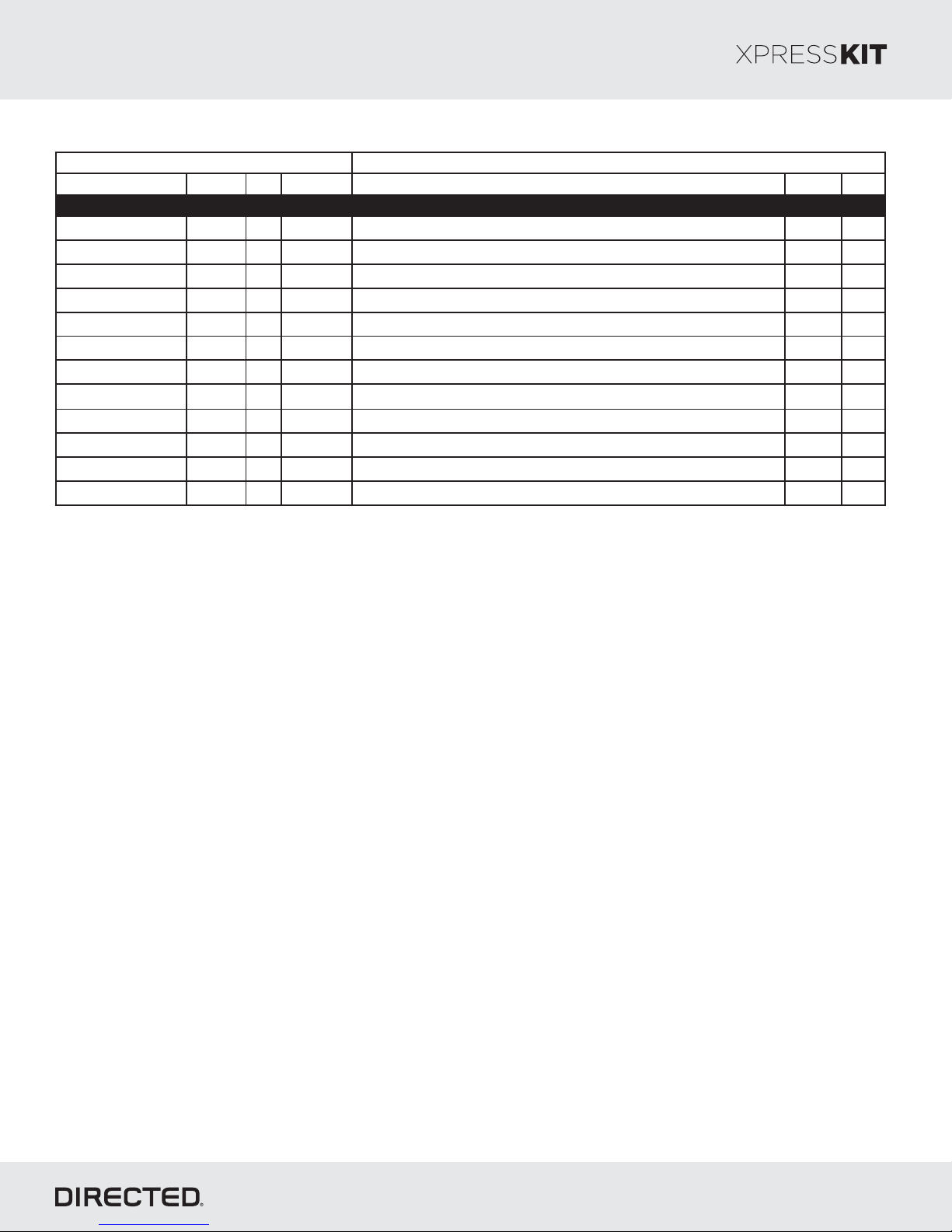
Platform: DBALL2
Function Color Pin Polarity Location Color Pins
HS CAN High Blue 6 Data Located at OBDII. Black 16
HS CAN Low White 14 Data Located at OBDII. Black 16
BTX Blue 25 Data Middle connector Body ECU on dash fuse box. White 30
BRX Red 26 Data Middle connector Body ECU on dash fuse box. W hite 30
Autolight Green 28 Cut Middle connector Body ECU on dash fuse box. W hite 30
12V Blue 16 (+) Located at OBDII. Black 16
Parking Lights W hite 30 (-) Middle connector Body ECU on dash fuse box. W hite 30
PTS Violet 30 (-) Top connector Certification ECU behind glove box. White 30
SLP Pink 4 (-) Steering Lock under steering column. Black 7
Lock Red 11 (-) Middle connector Body ECU on dash fuse box. White 30
Unlock Gray 24 (-) Middle connector Body ECU on dash fuse box. W hite 30
Trunk Release Red 5 (-) Body ECU on dash fuse box. White 28
Wire Information Connector Information
Lexus ES 350 (Smart Key) 2013-2015
Firmware TL6:
Vehicle -Wiring Reference Chart Type 1
Rev.: 20 708115
Page 6
© 201 Directed.7 All rights reserved.
Page 7
Platform: DBALL2
Firmware TL6:
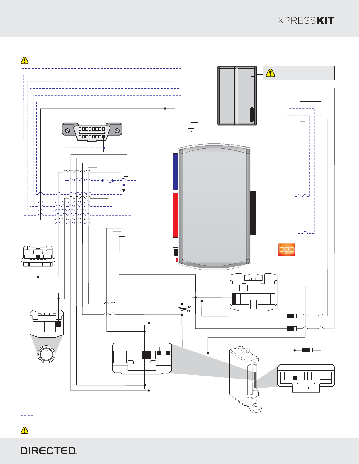
Installation Type 2
Driver Door Module
Diagnostic Connector OBD II
(connector side view)
18
(+) :12V pin 16Yellow,
Steering Lock
(black 7-pin
onnector)c
5
7
3
6
12
4
169
HS CA N High: 3Tan/Black:
Autolight Interrupt (conn.side): 8Yellow:
Autolight Interrupt (veh.side): 9Orange/Yellow:
Fuse 7.5A
(-) Push-to-Start Output: Green/Black: 2
(-) Door Status Output: Green/White: 3
(-) Trunk Status Output: Red/Black: 4
[1] ( ) Tach Output: 5AC Violet/White:
(+) Ignition Status Output: Gray/Black: 7
(-) Hood Status Output: 9Violet/Brown:
HS CA N Low: 4Tan:
(-) Output:SLP 11Yellow :/Red
(-) Ground: 12Brown :/Red
(+) 12V :Input 13Red:
(-) Ground: 14Black:
(-) E-Brake :Status
(+) Brake Output: Gray: 6
Immo Data 1: Yellow/Black: 10
Immo Data 2: Orange/Black: 11
(-) Lock Output: Blue/Red: 12
Black/White: 1
(-) Hood Status Input
(+) Brake Input
[1] ( ) T Status InputAC ach
(-) Trunk Status Input
(-) Door Status Input
(-) E-Brake Status Input
(+) Ignition Input/Output
(+) 12V
(+) 12V Input
(-) Ground
14
12
2
RF
Prog utton. B
LED
Remote
Starter
10
4
2DBALL
Do not connect these wires:
accessory ignition starter, , from
the remote starter to the vehicle.
(-) OutputLock
(-) OutputUnlock
(-) Trunk OutputRelease
(+) Starter Output
(-) (Status)GWR
()- Parking Lights Output
10: Blue/White:
(-) (Status) InputGWR
9: (+) Ignition InputPink:
8: (+) Starter InputViolet:
(+)12V
RX
(-) Ground
TX
P#: 2D65XKD
Rev.: 20 708115
Page 7
(-) SLP:
Blue, in 4P
15
16
24
Main
Body
ECU
56
141312 11
34
(-) :PTS
109876
ENGINE
START
STOP
Push-to-Start
(black onnector)10-pin c
(-) :Lock
Gray, pin 16
pin 1Green,
2345
1
BRX:
BTX:
24
2625
1413 1527181716
White or Green,
pin 26
29
28
(-) Parking lights:
6
5
4
HS CAN High:
(-) Autolight:
Red, pin 28
pin 30Black,
pin 14Pink or White,
Body ECU
(white -pin30
onnector)c
Black, pin 25
20
19
21 30
2223
8
7
9
10 12
11
2
3
1
HS CAN Low:
Violet, pin 13
(-) :Unlock
pin 24Violet,
Not required in D2D mode.
[1] Tach wire is an optional connection required on some remote starters, which do not support a tach signal in D2D.
Unless specified otherwise, all connectors are displayed from the wire side, with the exception of the diagnostic connector.OBDII
Driver Door
Module
12
87
9
10
20212223
171819
24(white -pin
onnector)c
Diode 1A
Diode 1A
Diode 1A
(-) ReleaseTrunk :
Yellow, pin 8
20
17
18 19
5
8
1
2
Body ECU
(white 28-pin onnector)c
2223
10976
25 2724 2623
13 1512 1411
28
16
34
© 201 Directed.7 All rights reserved.
Page 8
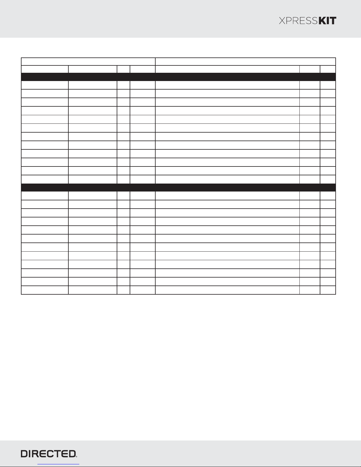
Platform: DBALL2
Function Color Pin Polarity Location Color Pins
HS CAN High Pink or W hite 14 Data Middle connector Body ECU on dash fuse box. W hite 30
HS CAN Low Violet 13 Data Middle connector Body ECU on dash fuse box. White 30
BTX Black 25 Data Middle connector Body ECU on dash fuse box. W hite 30
BRX White or Green 26 Data Middle connector Body ECU on dash fuse box. White 30
Autolight Red 28 Cut Middle connector Body ECU on dash fuse box. White 30
12V Yellow 16 (+) Located at OBDII. Black 16
Lock Gray 16 (-) Driver Door Module. White 24
Unlock Violet 24 (-) Driver Door Module. W hite 24
Parking Lights Black 30 (-) Middle connector Body ECU on dash fuse box. White 30
PTS Green 1 (-) Push-to-Start Switch. Black 10
SLP Blue 4 (-) Steering Lock under steering column. Black 7
Trunk Release Yellow 8 (-) Body ECU on dash fuse box. White 28
Wire Information Connector Information
Lexus GS 350 (Smart Ke y) 2013-2015
Lexus GS 450h (Sma rt Key) 2013-2015
Firmware TL6:
Vehicle - 2Wiring Reference Chart Type
Rev.: 20 708115
Page 8
© 201 Directed.7 All rights reserved.
Page 9
Platform: DBALL2
Firmware TL6:
Install Typeation 3
Rev.: 20 708115
Page 9
Steering Lock
(black onnector)7-pin c
5
7
6
4
Diagnostic Connector OBD II
(connector side view)
HS CA N High:
pin 6Blue,
18
169
(+) :12V
Blue,
pin 16
3
12
(-) SLP:
Pink, pin 4
HS CA N Low:
pin 14White,
HS CA N High: 3Tan/Black:
Autolight Interrupt (conn.side): 8Yellow:
Autolight Interrupt (veh.side): 9Orange/Yellow:
Fuse 7.5A
(-) E-Brake : 1Status Black/White:
(-) Push-to-Start Output: Green/Black: 2
(-) Door Status Output: Green/White: 3
(-) Trunk Status Output: Red/Black: 4
[1] ( ) Tach Output: 5AC Violet/White:
(+) Ignition Status Output: Gray/Black: 7
(-) Hood Status Output: 9Violet/Brown:
Immo Data 2: Orange/Black: 11
HS CA N Low: 4Tan:
(-) Output:SLP 11Yellow :/Red
(-) Ground: 12Brown :/Red
(+) 12V :Input 13Red:
(-) Ground: 14Black:
(+) Brake Output: Gray: 6
Immo Data 1: Yellow/Black: 10
(-) Lock Output: Blue/Red: 12
(-) Hood Status Input
(+) Brake Input
[1] ( ) T Status InputAC ach
(-) Trunk Status Input
(-) Door Status Input
(-) E-Brake Status Input
(+) Ignition Input/Output
(+) 12V
(+) 12V Input
(-) Ground
14
12
2
RF
Prog utton. B
LED
Remote
Starter
2DBALL
Do not connect these wires:
accessory ignition starter,,
from the remote starter to the vehicle.
(-) OutputLock
(-) OutputUnlock
(-) Trunk OutputRelease
(+) Starter Output
(-) (Status)GWR
(-) Parking Lights Output
10: Blue/White:
(-) (Status) InputGWR
10
9: (+) Ignition InputPink:
8: (+) Starter InputViolet:
(+)12V
RX
4
(-) Ground
TX
P#: 2D65XKD
Diode 1A
(-) : iPTS Violet, p n 17
Body ECU
7
17 16 15 14 13 12 11 10 9 8
24
25
30
31
Power Managment leftECU
ray 31-pin connector(g )
4
6
3
5
2
22
2021
23
29
28
1
19
18
26
27
(white 30-pin
onnector)c
Not required in D2D mode.
[1] Tach wire is an optional connection required on some remote starters, which do not support a tach signal in D2D.
Unless specified otherwise, all connectors are displayed from the wire side, with the exception of the diagnostic connector.OBDII
(-) :Lock
pin 11Red,
20
19
21
8
7
9
2
3
1
Blue, pin 25
22
23
10 12
11
BTX:
(-) :Unlock
24
2625
13 1527181716
14
pin 24Gray,
BRX:
29
28
30
6
5
4
pin 26Red,
(-) :Parking lights
pin 30White,
(-) lights:Auto
pinGreen, 28
Main
Body
ECU
Diode 1A
Diode 1A
(-) Release:Trunk pin 5Red,
20
17
18 19
5
1
2
Body ECU
(white 28-pin onnector)c
2223
109876
25 2724 2623
13 1512 1411
28
16
34
© 201 Directed.7 All rights reserved.
Page 10

Platform: DBALL2
Function Color Pin Polarity Location Color Pins
HS CAN High Blue 6 Data Located at OBDII. Black 16
HS CAN Low White 14 Data Located at OBDII. Black 16
BTX Blue 25 Data Middle connector Body ECU on dash fuse box. White 30
BRX Red 26 Data Middle connector Body ECU on dash fuse box. W hite 30
Autolight Green 28 Cut Middle connector Body ECU on dash fuse box. W hite 30
12V Blue 16 (+) Located at OBDII. Black 16
Lock Red 11 (-) Middle connector Body ECU on dash fuse box. W hite 30
Unlock Gray 24 (-) Middle connector Body ECU on dash fuse box. W hite 30
Parking Lights W hite 30 (-) Middle connector Body ECU on dash fuse box. W hite 30
PTS Violet 17 (-) Power Management ECU left of dash fuse box. Gray 31
SLP Pink 4 (-) Steering Lock under steering column. Black 7
Trunk Release Red 5 (-) Bottom connector Body ECU on dash fuse box. White 28
Wire Information Connector Information
Lexus ES 300h (Smart Key) 2013-2015
Firmware TL6:
Vehicle - 3Wiring Reference Chart Type
Rev.: 20 708115
Page 10
© 201 Directed.7 All rights reserved.
Page 11

Platform: DBALL2
Firmware TL6:
Installation Type 4
Rev.: 20 708115
Page 11
Steering Lock
(black 7-pin onnector)c
5
7
6
4
(-) SLP:
pin 4
Push-toStart
(Black 10-pin onnector)c
109876
Diagnostic Connector OBD II
(connector side view)
HS CA N High pin 6:
18
HS CA N Low: pin 14
3
12
(-) PTS:
pin 1
2345
1
169
(+) :12V
pin 16
HS CA N High: 3Tan/Black:
Autolight Interrupt (conn.side): 8Yellow:
Autolight Interrupt (veh.side): 9Orange/Yellow:
Fuse 7.5A
(-) E-Brake : 1Status Black/White:
(-) Push-to-Start Output: Green/Black: 2
(-) Door Status Output: Green/White: 3
(-) Trunk Status Output: Red/Black: 4
[1] ( ) Tach Output: 5AC Violet/White:
(+) Ignition Status Output: Gray/Black: 7
(-) Hood Status Output: 9Violet/Brown:
HS CA N Low: 4Tan:
(-) Output:SLP 11Yellow :/Red
(-) Ground: 12Brown :/Red
(+) 12V :Input 13Red:
(-) Ground: 14Black:
(+) Brake Output: Gray: 6
Immo Data 1: Yellow/Black: 10
Immo Data 2: Orange/Black: 11
Body ECU
(white 30-pin onnector)c
BTX: pin 25
20
19
8
7
2
1
24
21 30
2223
9
10 12
11
3
BRX: pin 26
(-) Hood Status Input
[1] ( ) T Status InputAC ach
(-) Trunk Status Input
(-) Door Status Input
(-) E-Brake Status Input
(+) Ignition Input/Output
(+) 12V
14
12
2
29
28
2625
14 1527181716
13
5
4
(-) lights: pinAuto 28
(+) Brake Input
(+) 12V Input
(-) Ground
RF
Prog utton. B
LED
(-) Parking lights: pin 30
6
Remote
Starter
2DBALL
Do not connect these wires:
accessory ignition starter,,
from the remote starter to the vehicle.
(-) OutputLock
(-) OutputUnlock
(-) Trunk Output
(+) Starter Output
(-) (Status)GWR
(-) Parking Lights Output
10: Blue/White:
(-) (Status) InputGWR
9: (+) Ignition InputPink:
10
8: (+) Starter InputViolet:
3: (-) Trunk InputRed/White:
2: (-) Unlock InputBlue:
1: (-) Lock InputGreen:
(+)12V
RX
4
(-) Ground
P#: 2D65XKD
TX
ENGINE
START
STOP
Not required in D2D mode.
[1] Tach wire is an optional connection required on some remote starters, which do not support a tach signal in D2D.
Unless specified otherwise, all connectors are displayed from the wire side, with the exception of the diagnostic connector.OBDII
© 201 Directed.7 All rights reserved.
Page 12

Platform: DBALL2
Function Color Pin Polarity Location Color Pins
HS CAN High Blue 6 Data Located at OBDII. White 16
HS CAN Low W hite 14 Data Located at OBDII. W hite 16
BTX
Brown 25 Data Body ECU on dash fuse box. W hite 30
BRX
Lt. Green 26 Data Body ECU on dash fuse box. White 30
Autolight Tan 28 Cut Body ECU on dash fuse box. W hite 30
12V Red 16 (+) Located at OBDII. White 16
Parking Lights Red 30 (-) Body ECU on dash fuse box. W hite 30
PTS Violet 1 (-) Push-to-Start Switch. Black 10
SLP Green 4 (-) Steering Lock under steering column. Black 7
HS CAN High Blue 6 Data Located at OBDII. White 16
HS CAN Low W hite 14 Data Located at OBDII. White 16
BTX
Green 25 Data Body ECU on dash fuse box. W hite 30
BRX
Red 26 Data Body ECU on dash fuse box. W hite 30
Autolight Green 28 Cut Body ECU on dash fuse box. W hite 30
12V Red 16 (+) Located at OBDII. White 16
Parking Lights White or Black 30 (-) Body ECU on dash fuse box. White 30
PTS Violet 1 (-) Push-to-Start Switch. Black 10
SLP Pink 4 (-) Steering Lock under steering column. Black 7
HS CAN High Blue 6 Data Located at OBDII. White 16
HS CAN Low W hite 14 Data Located at OBDII. White 16
BTX Green 25 Data Body ECU on das h fuse box. Whit e 30
BRX Red 26 Data Body ECU on dash fuse box. W hite 30
Autolight Green 28 Cut Body ECU on das h fuse box. Whit e 30
12V Red 16 (+) Located at OBDII. White 16
Parking Lights White or Black 30 (-) Body ECU on das h fuse box. Whit e 30
PTS Violet 1 (-) Push-to-Start Switch. Black 10
SLP Red 4 (-) Steering Loc k under steering c olumn. Black 7
HS CAN High Gray 6 Data Located at OBDII. White 16
HS CAN Low W hite 14 Data Located at OBDII. White 16
BTX Blac k 25 Data Body ECU on das h fuse box. Whit e 30
BRX Red 26 Data Body ECU on dash fuse box. W hite 30
Autolight Red 28 Cut Body ECU on dash fuse box. White 30
12V Lt. Blue 16 (+) Located at OBDII. White 16
Parking Lights Lt. Blue 30 (-) Body ECU on das h fuse box. White 30
PTS Lt. Blue 1 (-) Push-to-Start Switch. White 10
SLP Pink 4 (-) Steering Lock under steering column. Black 7
Toyota Prius C (Sma rt key) 2012-2014
Toyota Camry Hybrid (Sma rt Key) 2012-2015
Wire Information Connector Information
Toyota Avalon (Sma rt Ke y) 2013-2015
Toyota Camry (Smart Ke y) 2012-2015
Toyota Avalon Hybrid 2013-2015
Firmware TL6:
Vehicle - 4Wiring Reference Chart Type
Rev.: 20 708115
Page 12
© 201 Directed.7 All rights reserved.
Page 13

Platform: DBALL2
Function Color Pin Polarity Location Color Pins
HS CAN High Black 6 Data Located at OBDII. Black 16
HS CAN Low White 14 Data Located at OBDII. Black 16
BTX Blue 25 Data Body ECU on dash fuse box. White 30
BRX Red 26 Data Body ECU on dash fuse box. White 30
Autolight Green 28 Cut Body ECU on dash fuse box. White 30
12V Blue 16 (+) Located at OBDII. Black 16
Parking Lights White 30 (-) Body ECU on dash fuse box. White 30
PTS Dk. Green 1 (-) Push-to-Start Switch. Black 10
SLP Green 4 (-) Steering Lock under steering column. Black 7
Wire Information Connector Information
Toyota RAV4 (Smart Key) 2013-2015
Firmware TL6:
Rev.: 20 708115
Page 13
© 201 Directed.7 All rights reserved.
Page 14

Platform: DBALL2
Firmware TL6:
Installation Type 5
Rev.: 20 708115
Page 14
Steering Lock
(black 7-pin
nnector)co
5
7
3
6
4
Diagnostic Connector OBD II
(connector side view)
HS CA N High pin 6: Red,
18
HS CA N Low:
White, pin 14
12
169
(+) :12V
Green, pin 16
HS CA N High: 3Tan/Black:
Autolight Interrupt (conn.side): 8Yellow:
Autolight Interrupt (veh.side): 9Orange/Yellow:
Fuse 7.5A
(-) E-Brake : 1Status Black/White:
(-) Push-to-Start Output: Green/Black: 2
(-) Door Status Output: Green/White: 3
(-) Trunk Status Output: Red/Black: 4
[1] ( ) Tach Output: 5AC Violet/White:
(+) Ignition Status Output: Gray/Black: 7
(-) Hood Status Output: 9Violet/Brown:
Immo Data 2: Orange/Black: 11
HS CA N Low: 4Tan:
(-) Output:SLP 11Yellow :/Red
(-) Ground: 12Brown :/Red
(+) 12V :Input 13Red:
(-) Ground: 14Black:
(+) Brake Output: Gray: 6
Immo Data 1: Yellow/Black: 10
(-) Hood Status Input
(+) Brake Input
[1] ( ) T Status InputAC ach
(-) Trunk Status Input
(-) Door Status Input
(-) E-Brake Status Input
(+) Ignition Input/Output
(+) 12V
(+) 12V Input
(-) Ground
14
12
2
RF
Prog utton. B
LED
Remote
Starter
Do not connect these wires:
accessory ignition starter,,
from the remote starter to the vehicle.
(-) OutputLock
(-) OutputUnlock
(-) Trunk Output
(+) Starter Output
(-) (Status)GWR
(-) Parking Lights Output
10: Blue/White:
(-) (Status) InputGWR
9: (+) Ignition InputPink:
10
8: (+) Starter InputViolet:
3: (-) Trunk InputRed/White:
2: (-) Unlock InputBlue:
1: (-) Lock InputGreen:
(+)12V
RX
4
(-) Ground
2DBALL
TX
P#: 2D65XKD
(-) SLP:
Green,
pin 4
(-) PTS:
Black, pin 1
2345
ENGINE
START
STOP
1
109876
Push-to-Start
(black 10-pin onnector)c
Not required in D2D mode.
[1] Tach wire is an optional connection required on some remote starters,
which do not support a tach signal in D2D.
Unless specified otherwise, all connectors are displayed from the wire side, with the exception of the diagnostic connector.OBDII
Solder onto a diode, cut away the unneeded
portion, and then insert into empty pin as shown.
Solder the
wire to secure
it on the metal
pin.
Diodes
This part can be removed because
only the metal pin is needed to
secure the contact in the empty pin.
BTX: pin 25
Body ECU
(white 30-pin
Connector)
20
19
21 30
2223
8
7
9
10 12
2
3
1
BRX:
pin 26
24
11
28
2625
1527181716
14
13
4
29
(-) Parking lights:
6
5
(-) Autolight:
pViolet, in 28
p30White, in
Main
Body
ECU
© 201 Directed.7 All rights reserved.
Page 15

Platform: DBALL2
Function Color Pin Polarity Location Color Pins
HS CAN High Red 6 Data Located at OBDII. White 16
HS CAN Low White 14 Data Located at OBDII. W hite 16
12V Green 16 (+) Located at OBDII. White 16
SLP Green 4 (-) Steering Lock under steering column. Black 7
BTX Empty 25 Data Middle connector Body ECU on dash fuse box. White 30
BRX Empty 26 Data Middle connector Body ECU on dash fuse box. White 30
Parking Lights W hite 30 (-) Middle connector Body ECU on dash fuse box. W hite 30
Autolight Violet 28 cut Middle connector Body ECU on dash fuse box. White 30
PTS Black 1 (-) Push-to-Start Switch. Black 10
Wire Information Connector Information
Toyota Corolla Smart key 2014-2016
Firmware TL6:
Vehicle - 5Wiring Reference Chart Type
Rev.: 20 708115
Page 15
© 201 Directed.7 All rights reserved.
Page 16

Platform: DBALL2
Firmware TL6:
Installation Type 6
Rev.: 20 708115
Page 16
Diagnostic Connector OBD II
(connector side view)
18
169
(+) :12V pin 16
Fuse 7.5A
[1] ( ) T Status InputAC ach
(-) E-Brake Status Input
(+) Ignition Input/Output
HS CA N High: 3Tan/Black:
Autolight Interrupt (conn.side): 8Yellow:
Autolight Interrupt (veh.side): 9Orange/Yellow:
(-) E-Brake : 1Status Black/White:
(-) Push-to-Start Output: Green/Black: 2
(-) Door Status Output: Green/White: 3
(-) Trunk Status Output: Red/Black: 4
[1] ( ) Tach Output: 5AC Violet/White:
(+) Ignition Status Output: Gray/Black: 7
(-) Hood Status Output: 9Violet/Brown:
HS CA N Low: 4Tan:
(-) Output:SLP 11Yellow :/Red
(-) Ground: 12Brown :/Red
(+) 12V :Input 13Red:
(-) Ground: 14Black:
(+) Brake Output: Gray: 6
Immo Data 1: Yellow/Black: 10
Immo Data 2: Orange/Black: 11
(-) Hood Status Input
(+) Brake Input
(-) Trunk Status Input
(-) Door Status Input
(+) 12V Input(+) 12V
(-) Ground
14
12
2
RF
Prog utton. B
LED
Remote
Starter
Do not connect these wires:
accessory ignition starter,,
from the remote starter to the vehicle.
(-) OutputLock
(-) OutputUnlock
(-) Trunk Output
(+) Starter Output
(-) (Status)GWR
(-) Parking Lights Output
10: Blue/White:
(-) (Status) InputGWR
9: (+) Ignition InputPink:
10
8: (+) Starter InputViolet:
3: (-) Trunk InputRed/White:
2: (-) Unlock InputBlue:
1: (-) Lock InputGreen:
(+)12V
RX
4
(-) Ground
2DBALL
TX
P#: 2D65XKD
Steering Lock
(black or Blue
c7-pin onnector)
5
7
3
6
4
(-) :SLP
pin 4
(-) PTS: pin 1
109876
2345
ENGINE
START
STOP
Push-toStart
(black 10-pin
onnector)c
12
Solder onto a diode, cut away the unneeded
portion, and then insert into empty pin as shown.
Solder the
wire to secure
1
it on the metal
pin.
Diodes
This part can be removed because
only the metal pin is needed to
secure the contact in the empty pin.
(-) lights: pinAuto 28
HS CAN High: pin 14
6
Body ECU
(white 30-pin
onnector)c
(-) Parking lights:
18
3030
pin 30
5
4
17
16
15
29
28
27
BRX: pin 26 BTX: pin 25
Not required in D2D mode.
[1] Tach wire is an optional connection required on some remote starters, which do not support a tach signal in D2D.
Unless specified otherwise, all connectors are displayed from the wire side, with the exception of the diagnostic connector.OBDII
FUSE
BODY ECU
HS CAN Low: pin 13
14
13
111210
25
26
23
22
24
2
1
3
8
7
9
20
19
21
© 201 Directed.7 All rights reserved.
Page 17

Platform: DBALL2
Function Color Pin Polarity Location Color Pins
12V Red 16 (+) Located at OBDII. Black 16
SLP Green 4 (-) Steering Lock under steering column. Black or Blue 7
HS CAN High Pink 14 Data Body ECU on bottom dash fuse box. White 30
HS CAN Low White 13 Data Body ECU on bottom dash fuse box. White 30
BTX Brown 25 Data Body ECU on bottom dash fuse box. White 30
BRX Lt. Green 26 Data Body ECU on bottom dash fuse box. White 30
Parking Lights Red 30 (-) Body ECU on bottom dash fuse box. White 30
Autolight Tan 28 cut Body ECU on bottom dash fuse box. White 30
PTS Violet 1 (-) Push-to-Start Switch. Black 10
SLP Green or Pink 4 (-) Steering lock under steering column. Black or Blue 7
PTS Violet 1 (-) PTS (Push-to-Start) switch. Black 10
12V Red 16 (+) OBDII. Black 16
BTX Green 25 Data Body ECU on bottom dash fuse box. White 30
BRX Red 26 Data Body ECU on bottom dash fuse box. White 30
Parking Lights Black 30 (-) Body ECU on bottom dash fuse box. White 30
Autolight Green 28 cut Body ECU on bottom dash fuse box. White 30
HS CAN High Pink 14 Data Body ECU on bottom dash fuse box. White 30
HS CAN Low White 13 Data Body ECU on bottom dash fuse box. White 30
Toyota Camry Hybrid (Sma rt Key) 2016-2017
SLP Green or Pink 4 (-) Steering lock under steering column. Black or Blue 7
PTS Violet 1 (-) PTS (Push-to-Start) switch. Black 10
12V Red 16 (+) OBDII. Black 16
BTX Green 25 Data Body ECU on bottom dash fuse box. White 30
BRX Red 26 Data Body ECU on bottom dash fuse box. White 30
Parking Lights Black 30 (-) Body ECU on bottom dash fuse box. White 30
Autolight Green 28 cut Body ECU on bottom dash fuse box. White 30
HS CAN High Pink 14 Data Body ECU on bottom dash fuse box. White 30
HS CAN Low White 13 Data Body ECU on bottom dash fuse box. White 30
Wire Information Connector Information
Toyota Avalon (Smart Key) 2016
Toyota Camry (Smart Key) 2016-2017
Toyota Avalon Hybrid 2016
Firmware TL6:
Rev.: 20 708115
Vehicle -Wiring Reference Chart Type 6
© 201 Directed.7 All rights reserved.
Page 17
Page 18

Platform: DBALL2
Function Color Pin Polarity Location Color Pins
Toyota Corolla (Smart Key) 2017
SLP Green 4 (-) Steering lock under steering column. Black 7
PTS Black 1 (-) PTS (Push-to-Start) switch. Black 10
12V Green 16 (+) OBDII. Black 16
BTX Empty, insert pin 25 Data Body ECU on bottom dash fuse box. White 30
BRX Empty, insert pin 26 Data Body ECU on bottom dash fuse box. White 30
Parking Lights White 30 (-) Body ECU on bottom dash fuse box. White 30
Autolight Violet 28 cut Body ECU on bottom dash fuse box. White 30
HS CAN High Black 14 Data Body ECU on bottom dash fuse box. White 30
HS CAN Low White 13 Data Body ECU on bottom dash fuse box. White 30
Toyota RAV4 (Smart Ke y) 2016-2017
12V Blue 16 (+) Located at OBDII. Black 16
SLP Lt. Green 4 (-) Steering Lock under steering column. Black or Blue 7
HS CAN High Green 14 Data Body ECU on bottom dash fuse box. White 30
HS CAN Low White 13 Data Body ECU on bottom dash fuse box. White 30
BTX Blue 25 Data Body ECU on bottom dash fuse box. White 30
BRX Red 26 Data Body ECU on bottom dash fuse box. White 30
Parking Lights White 30 (-) Body ECU on bottom dash fuse box. White 30
Autolight Green 28 cut Body ECU on bottom dash fuse box. White 30
PTS Dk. Green 1 (-) Push-to-Start Switch. Black 10
Wire Information Connector Information
Firmware TL6:
Rev.: 20 708115
Page 18
© 201 Directed.7 All rights reserved.
Page 19

Platform: DBALL2
Firmware TL6:
Installation Type 7
Rev.: 20 708115
Page 19
Steering Lock
(black or Blue
c7-pin onnector)
5
7
3
6
4
(-) Hood Status Input
(+) Brake Input
[1] ( ) T Status InputAC ach
(-) Trunk Status Input
(-) Door Status Input
(-) E-Brake Status Input
(+) Ignition Input/Output
(+) 12V
Diagnostic Connector OBD II
(connector side view)
18
169
(+) :12V pin 16Blue,
Autolight Interrupt (conn.side): 8Yellow:
Autolight Interrupt (veh.side): 9Orange/Yellow:
Fuse 7.5A
(-) Push-to-Start Output: Green/Black: 2
(-) Door Status Output: Green/White: 3
(-) Trunk Status Output: Red/Black: 4
[1] ( ) Tach Output: 5AC Violet/White:
(+) Ignition Status Output: Gray/Black: 7
(-) Hood Status Output: 9Violet/Brown:
12
3
HS CA N High: 3Tan/Black:
HS CA N Low: 4Tan:
(-) Output:SLP 11Yellow :/Red
(-) Ground: 12Brown :/Red
(+) 12V :Input 13Red:
(-) Ground: 14Black:
(-) E-Brake : 1Status Black/White:
(+) Brake Output: Gray: 6
Immo Data 1: Yellow/Black: 10
Immo Data 2: Orange/Black: 11
(+) 12V Input
14
12
2
RF
Prog utton. B
LED
(-) Ground
Remote
Starter
(+) Start
Enable:
, pinLt. Blue 7
2
8 7
10 9
65
16
15
1718
1314
(-) OutputLock
(-) OutputUnlock
(-) Trunk Output
(+) Starter Output
(-) (Status)GWR
(-) Parking Lights Output
(+) Starter Output
1
43
1112
2DBALL
Do not connect these wires:
accessory ignition starter,,
from the remote starter to the vehicle.
Certification ECU
(white 18-pin
onnector)c
10: Blue/White:
(-) (Status) InputGWR
9: (+) Ignition InputPink:
8: (+) Starter InputViolet:
10
3: (-) Trunk InputRed/White:
2: (-) Unlock InputBlue:
1: (-) Lock InputGreen:
(+)12V
RX
4
(-) Ground
P#: 2D65XKD
TX
(-) :SLP
Lt. Green,
pin 4
HS CAN High: pin 14Green,
(-) lights:Auto
(-) PTS:
109876
Push-toStart
(black 10-pin onnector)c
pin 1Dk. Green,
ENGINE
2345
1
START
STOP
Body ECU
White 30-pin
onnectorc
Not required in D2D mode.
[1] Tach wire is an optional connection required on some remote starters, which do not support a tach signal in D2D.
Unless specified otherwise, all connectors are displayed from the wire side, with the exception of the diagnostic connector.OBDII
, pinGreen 28
5
4
6
17
16
18
3030
15
29
28
27
BRX: Red,
26pin
(-) Parking lights:
pin 30White,
HS CAN Low:,White pin 13
2
3
14
13
111210
25
26
23
24
8
9
20
21
22
BRX: 25Blue, pin
1
7
19
FUSE
BODY ECU
© 201 Directed.7 All rights reserved.
Page 20

Platform: DBALL2
Function Color Pin Polarity Location Color Pins
HS CAN High Green 14 Data Body ECU on bottom dash fuse box. White 30
HS CAN Low White 13 Data Body ECU on bottom dash fuse box. White 30
BTX Blue 25 Data Body ECU on bottom dash fuse box. White 30
BRX Red 26 Data Body ECU on bottom dash fuse box. White 30
Autolight Green 28 Cut Body ECU on bottom dash fuse box. White 30
12V Blue 16 (+) Located at OBDII. White 16
Parking Lights White 30 (-) Body ECU on bottom dash fuse box. White 30
PTS Dk. Green 1 (-) Push-to-Start Switch. Black 10
Start Enable Lt. Blue 7 (+) Certification ECU behind glovebox. White 18
SLP Lt. Green 4 (+) Steering Lock under column. Black 7
Wire Information Connector Information
Toyota RAV4 Hybrid (Smart Key) 2016-2017
Firmware TL6:
Vehicle - 7Wiring Reference Chart Type
Rev.: 20 708115
Page 20
© 201 Directed.7 All rights reserved.
Page 21

Platform: DBALL2
Firmware TL6:
Installation Type 8
Rev.: 20 708115
Page 21
Diagnostic Connector OBD II
(connector side view)
18
(+) 12V: Black or White,
( Trunk Release-) : pin 8Yellow,
HS CA N 2 Low: pin 10Gray,
20
2223
17
18 19
5
8
1
2
25 2724 2623
10976
13 1512 1411
HS CA N 2 High: pin 9Red,
p n 16i
34
169
Body ECU
28
16
(white 28-pin
onnector)c
(-) Hood Status Input
(+) Brake Input
( ) T Status InputAC ach
[1]
(-) Trunk Status Input
(-) Door Status Input
(-) E-Brake Status Input
(+) Ignition Input/Output
(+) 12V Input
(-) Ground
Body ECU
(white30-pin
onnector)c
Remote
Starter
BTX:
pin 25Black,
20
19
8
7
2
1
HS CA N Low 1:
Gray or White, pin 13
24
21 30
2223
9
10 12
11
3
Do not connect these wires:
accessory ignition starter,,
from the remote starter to the vehicle.
(-) OutputLock
(-) OutputUnlock
(-) Trunk OutputRelease
(+) Starter Output
(-) (Status)GWR
(-) Parking Lights Output
BRX: Green
or White,
pin 26
29
28
2625
1413 1527181716
HS CA N High 1:
Red, pin 14
5
4
(-) Parking lights:
Black, p n 30i
6
Autolight Interrupt:
in 28Red, p
HS CA N 1 High: 3Tan/Black:
HS CA N 1 Low: 4Tan:
(-) Output:SLP 11Yellow :/Red
(-) Ground: 12Brown :/Red
(+) 12V :Input 13Red:
(-) Ground: 14Black:
(-) E-Brake : 1Status Black/White:
(+) Brake Output: Gray: 6
Immo Data 1: Yellow/Black: 10
Immo Data 2: Orange/Black: 11
14
14
12
12
2
2
RF
RF
Prog utton. B
Prog utton. B
LED
LED
P#: 2D65XKD
2DBALL
2DBALL
(-) SLP:
Blue, pin 4
5
7
3
6
4
Steering Lock
(Black 7-pin
onnector)c
HS CA N 2 High: 5Orange Green/:
HS CAN 2 : 6Low Orange Brown/:
Autolight Interrupt (conn.side): 8Yellow:
Autolight Interrupt (veh.side): 9Orange/Yellow:
(+) 12V
(-) Push-to-Start Output: Green/Black: 2
(-) Door Status Output: Green/White: 3
(-) Trunk Status Output: Red/Black: 4
[1] ( ) Tach Output: 5AC Violet/White:
(+) Ignition Status Output: Gray/Black: 7
(-) Hood Status Output: 9Violet/Brown:
(-) :PTS
pin 1Green,
12
109876
(black 10-pin onnector)c
2345
Push-to-Start
ENGINE
START
1
STOP
Not required in D2D mode.
[1] Tach wire is an optional connection required on some remote starters, which do not support a tach signal in D2D.
Unless specified otherwise, all connectors are displayed from the wire side, with the exception of the diagnostic connector.OBDII
10: Blue/White:
(-) (Status) InputGWR
9: (+) Ignition InputPink:
10
10
8: (+) Starter InputViolet:
2: (-) Unlock InputBlue:
1: (-) Lock InputGreen:
(+)12V
4
4
RX
(-) Ground
TX
© 201 Directed.7 All rights reserved.
Page 22

Platform: DBALL2
Function Color Pin Polarity Location Color Pins
HS CAN 1 High Red 14 Data Middle connector Body ECU on dash fuse box. White 30
HS CAN 1 Low Gray or W hite 13 Data Middle connector Body ECU on dash fuse box. White 30
HS CAN 2 High Red 9 Data Bottom 28 pin connector of ECU. White 28
HS CAN 2 Low Gray 10 Data Bottom 28 pin connector of ECU. White 28
BTX Black 25 Data Middle connector Body ECU on dash fuse box. White 30
BRX Green or W hite 26 Data Middle connector Body ECU on dash fuse box. White 30
Autolight Red 28 Cut Middle connector Body ECU on dash fuse box. White 30
12V Black or White 16 (+) Located at OBDII. Black 16
Parking Lights Black 30 (-) Middle connector Body ECU on dash fuse box. White 30
PTS Green 1 (-)
Push-to-Start Switch. Black 10
SLP Blue 4 (-)
Steering Lock under steering column. Black 7
Trunk Release Yellow 8 (-) Bottom 28 pin connector of ECU. White 28
Wire Information
Connector Information
Lexus G350 (Sma rt Key) 2016
Firmware TL6:
Vehicle - 8Wiring Reference Chart Type
Rev.: 20 708115
Page 22
© 201 Directed.7 All rights reserved.
Page 23

Platform: DBALL2
Firmware TL6:
Rev.: 20 708115
Module Programming
Refer to the Diagnostics section for more information and for troubleshooting purposes.LED
Important
Make all the required connections to the vehicle, as described in the wiring diagram(s) found in this guide, and double check to
ensure everything is correct prior to moving onto the next step.
Warning! To take advantage of advanced features, you must use Xpress 4.5 (and higher) or the Directechs Mobile app.VIP
Flashing a module using your computer:
1. Connect the interface module to your computer using the
XKLoader2.
2. Go to www.directechs.com using Internet Explorer, and
select the button.Flash Module
3. Follow the instructions to select your vehicle, installation
type, and configure your options.
4. Once you have configured the firmware options, click on the
FLASH button.
When the flashing operation is successful, you can proceed with the programming instructions below.
Flashing a module using your smartphone or tablet
1. Connect the interface module to your oader3.XKL
2. Launch the Directechs Mobile app on your smartphone or
tablet.
3. Select and follow the on screenFLASH YOUR MODULE
instructions.
Page 23
D2D Installation
If required for your installation, connect the 10-pin, 12-pin and 14-pin harnesses to
the module, then connect the 4-pin D2D harness.
OR
W W Installation2
If required for your installation, connect the 10-pin and 12-pin harnesses to the
module, then connect the 14-pin harness to the module.
1
2
3
4
Wait until the LED turns solid red.ON
Wait 4 seconds before turning the ignition ON.
The the isLED OEMflashes orange if remote starter detected.
()See page 3 for more information .
Press the ush-to- tart button to turn the ignitionPS()PTS twice
ON LED ON. The green turns for 3 seconds and shuts .OFF
If the flashes orange, programming button 5 .LED press the times
The turns solid orange for 3 seconds: the programming is done.LED
Otherwise proceed to the next step.
4
th
1
1
ENGINE
START
STOP
D2D
st
D2D
st
10-pin
10-pin
PUSH 2X
Flashes
14-pin
12-pin
rd
3
nd
2
14-pin
12-pin
rd
3
nd
2
Flashes
& &
Solid x3 Secs Off
&&
Solid x3 sec.Press x5
Solid
5
Press the button more to turn the ignition .PTS OFFonce
You have successfully completed the module programming sequence.
ENGINE
START
PUSH 1X
STOP
© 201 Directed.7 All rights reserved.
Page 24

Platform: DBALL2
Firmware TL6:
Rev.: 20 708115
Page 24
Module Reset
A module reset will only erase programming performed in the previous steps. All settings (firmware) and settings flashed
to the module using the web config tool will not be affected.
D2D Installation
If required for your installation, c , &onnect the 10-pin 12-pin
14-pin harnesses to the module Press hold the. and
p , then connect the 4-pin D2D harness.rogramming button
D2D
10-pin
th
5
st
1
rd
3
14-pin
12-pin
nd
2
th
4
OR
1
2
Hard Reset
Warning gainst xecuting a Hard Reset!AE
A hard reset will revert the flashed firmware back to its default settings. Depending on the installation, some settings
(such as and D2D options) may have to be reconfigured. See the section of this guide.RFTD Feature & Option List
W2W Installation
If required for your installation, connect the 10-pin & 12-pin
harnesses to the module Press hold the rogramming. and p
button, then connect the 14-pin harness to the module.
Wait 3 seconds until the orange then release theLED turns solidON
p The then turns solid red.rogramming button. LED ON
D2D Installation
If required for your installation, c , &onnect the 10-pin 12-pin
14-pin harnesses to the module Press hold the. and
p , then connect the 4-pin D2D harness.rogramming button
D2D
10-pin
st
1
th
4
14-pin
12-pin
nd
2
rd
3
& &
rd
3
Release
nd
2
4
14-pin
th
12-pin
Solid Solid
D2D
10-pin
th
5
st
1
1
2
3
OR
W2W Installation
If required for your installation, connect the 10-pin & 12-pin
harnesses to the module Press hold the rogramming. and p
button, then connect the 14-pin harness to the module.
Wait 3 seconds until the orange aitLED turns solid , and w 10 more secondsON
until the andLED starts to flash orange red.
Release the programming button. The turns solid red.LED ON
D2D
10-pin
st
1
th
4
14-pin
12-pin
nd
2
rd
3
&
Solid
Flashes
&
Release
Solid
© 201 Directed.7 All rights reserved.
Page 25

Platform: DBALL2
* Default Option
Feat. Operation Flashes/Option Description
1. No RF Output* Module is connec ted to a remote s tarter us ing a s tandard installation.
2. RFTD Output Module is connec ted to an XL202 using an RS R or RXT ins tallation (when available).
3. SmartStart Module is connected to Sm artStart using an RSR or RXT installation (when available).
1. Driver priority* Unlocks only the driver door on first press and unlock s all doors on a second press within 5 s econds .
2. All Unloc ks all doors on first press.
RF Output1
Unlock Driver Priority2
Firmware TL6:
Rev.: 20 708115
Page 25
Feature and Option List
It is recommended to configure all features and options listed below thethe using configuration tool found on the module
flashing page on www.directechs.com. The web offers more options; however, manual configuration of the features is
possible using the information on this page.
Feature Programming
To enter feature programming routine
Changing feature options
Accessing another feature
When the maximum number of features or options is reached, the will start flashing again from the first feature or option.LED
Once a feature is programmed
Exiting feature programming
Programming
Button
-
Turn t , thenhe ignition .ON OFF
-
Within 5 seconds, press and the rogramming button turns after 3 seconds . Release theHOLD LED ONp until the orange ( )
Programming button.
-
The to indicate the feature number is 1. After a short delay, the flashes rapidly to indicateLED LEDwill flash green once slowly red
the current option of feature 1 . repeat(i.e. 1x green followed by 1x red indicates feature 1 is set to option 1) The flashing sequence will
until .a new command is entered
-
Press the arm or disarm button on aftermarket transmitter to change the option of the selected feature.lock/ unlock/
-
The flashes rapidly the number of times equal to the current option number. After a short delay, the flashes green slowlyLED LEDred
the number of times to indicate the current feature. repeat until .The flashing sequence will a new command is entered
-
Press and release the programming button a number of times to advance from the current feature to the next desired feature.
-
The flashes green slowly the number of times equal to the feature number. After a short delay, the flashes red rapidly toLED LED
indicate the current option of the current feature. repeat until .The flashing sequence will a new command is entered
-
Other features can be programmed.
-
The feature programming can be exited.
-
No activity for 30 seconds; after 30 seconds, the will turn orange for 2 seconds to confirm the end of the programmingLED ON
sequence.
OR
-
Press and the programming button for 3 seconds. After 3 seconds, the will turn orange for 2 seconds to confirm theHOLD LED ON
end of the programming sequence.
© 201 Directed.7 All rights reserved.
Page 26

Platform: DBALL2
LED Description Troubleshooting
Module has no power.
Make sure the D2D harness is connected or that the 12
Volt is present between the red and black wires. If the
12 Volt is present, the module may be defective.
Waiting t o begin the programming s equence.
Ensure the c orrect programming procedure is being
followed.
Initialization failed.
Reset the module and complete the programming again.
If the issue persists, please contact Technical Support.
Transponder functions were skipped.
(If compatible) when RXT mode is not desired or
convenience features are needed, please reset and
reprogram the module.
All required CAN networks has been detected. Normal operation.
1 of 2 CAN networks has been detected. Normal operation
Key2GO initiated.
Pleas e follow the s teps indicated in “Module
programming” to complete the Key2GO programming.
Module was successfully programmed with all funct ions . Normal operation
Module was successfully programmed without
transponder functions.
Normal operation.
CAN2 not detected.
Check the CAN2 Orange/Green and Orange/Brown wire
connections. Wake up the data bus by turning the
ignition on and try again. If your installation does not
require this connec tion, skip this step by pressing the
programming button 5 times.
J1850 not detect ed.
Check the J1850 wire connection. Wake up the data bus
by turning the ignition on and try again.
CAN1 not detected.
Check the CAN1 Tan and Tan/Blac k wire connections.
Wake up the data bus by t urning the ignition on and try
again. If your installation does not require this
connection, skip this step by pressing the programming
button 5 times.
Bypass data not detected.
Check the bypass line connection. If more than one wire
is used, make sure they are not inverted. Ensure the
vehic le still operates correctly using the factory key .
Bypas s processing error.
The bypass calculation failed. Reset the module and try
again. If the condition persists, please contact Technical
Support.
ISO 1 not detected.
The Yellow/Black wire did not detect the expected
signal. Refer to "Installation (wiring diagrams & vehicle
wiring reference charts )" to c heck the connections.
ISO 2 not detected.
The Orange/Black wire did not detect the expected
signal. Refer to "Installation (wiring diagrams & vehicle
wiring reference charts )" to c heck the connections.
MUX not detected.
The Violet/Green or Violet/Brown wire did not detect the
expected voltage value. Refer to "Installation (wiring
diagrams & vehicle wiring reference charts)" to c heck
the connections.
Module Programming
Module Programming - Error Code s
Firmware TL6:
LED Diagnostics & Troubleshooting
Off
Solid red
Flashes red
& green
Solid orange
Flashes
green
Flashes
orange
Flashes
orange
slowly
Solid green
x 3 secs
Rev.: 20 708115
Page 26
Solid orange
x 3 secs
Flashes red
x 1
Flashes red
x 1
Flashes red
x 2
Flashes red
x 3
Flashes red
x 4
Flashes red
x 5
Flashes red
x 6
Flashes red
x 7
© 201 Directed.7 All rights reserved.
Page 27

Platform: DBALL2
LED Description Troubleshooting
OBDII feature is not supported.
The diagnostic data bus was not detec ted, therefore the
SmartStart features will be limited.
Ground W hen Running (Status) command received. The module has initialized the remote start sequence.
Ignition ON command received.
The module has received the Ignition ON command and
is processing the remote start sequence.
Start ON command rec eived.
The module has received the Start ON command and is
processing the remote s tart sequence.
PTS s hutdown error.
The PTS out put from the module was not activated due
to safety protection.
CAN bus incorrectly detected.
Verify the CAN1 and CAN2 connec tions. Refer to
“Installation (wiring diagrams & vehicle wiring reference
charts)” to check the connections.
LOCK command received.
UNLOCK c ommand received.
TRUNK c ommand received.
AUX1 command received.
AUX2 command received.
AUX3 command received.
Takeover s uccess ful. Normal operation.
Runsafe was not disabled.
No UNLOCK command was received prior to opening the
door, or the 45 second timer expired in takeover mode.
Brake was not detected.
The brakes were not detected, which prevents the
system from shutting down the vehicle.
Smart key was not detected.
The smart key was not detected, which prevents the
system from shutting down the vehicle.
Speed was detected.
The vehicle was detected as moving, which prevents the
system from shutting it down.
External module synchronization
Commands
Activation Ground When Running (Status)
If the by pass module fails to flash, it did not receive the
signal. Commands can c ome from RF or D2D.
Shutdown codes
Firmware TL6:
(Flashes red,
red then
orange) x 10
Flashes
green
Flashes red
& orange
Flashes
green
quickly
Flashes red
x 10
Flashes red
x 21
Flashes
orange x 1
Flashes
orange x 2
Rev.: 20 708115
Page 27
Flashes
orange x 3
Flashes
orange x 4
Flashes
orange x 5
Flashes
orange x 6
Flashes
green x 1
Flashes red
x 1
Flashes red
x 2
Flashes red
x 3
Flashes red
x 4
© 201 Directed.7 All rights reserved.
Page 28

Platform: DBALL2
Firmware TL6:
Rev.: 20 708115
Page 28
Limited Consumer WarrantyOne Year
For a period of from the date of purchase of a Directed Electronics remote start or security product, DirectedONE YEAR
Electronics. (“ ”) promises to the original purchaser, to repair or replace with a comparable reconditioned piece, theDIRECTED
security or remote start accessory piece (hereinafter the “Part”), which proves to be defective in workmanship or material
under normal use, provided the following conditions are met: the Part was purchased from an authorized dealer;DIRECTED
and the Part is returned to , postage prepaid, along with a clear, legible copy of thereceipt or bill of sale bearing theDIRECTED
following information: consumer’s name, address, telephone number, the authorized licensed dealer’s name and complete
product and Part description.
This warranty is nontransferable and is automatically void if the Part has been modified or used in a manner contrary to its
intended purpose or the Part has been damaged by accident, unreasonable use, neglect, improper service, installation or
other causes not arising out of defect in materials or construction.
TO THE MAXIMUM EXTENT ALLOWED BY LAW EXCEPT AS STATED ABOVE ALL WARRANTIES INCLUDING,,,
BUT NOT LIMITED TO EXPRESS WARRANTY IMPLIED WARRANTY WARRANTY OF MERCHANTABILITY,, ,
FITNESS FOR PARTICULAR PURPOSE AND WARRANTY OF NONINFRINGEMENT OF INTELLECTUAL
PROPERTY ARE EXPRESSLY EXCLUDED AND DIRECTED NEITHER ASSUMES NOR AUTHORIZES ANY,;
PERSON OR ENTITY TO ASSUME FOR IT ANY DUTY OBLIGATION OR LIABILITY IN CONNECTION WITH ITS,
PRODUCTS DIRECTED HEREBY DISCLAIMS AND HAS ABSOLUTELY NO LIABILITY FOR ANYAND ALLACTS OF.
THIRD PARTIES INCLUDING DEALERS OR INSTALLERS DIRECTED IS NOT OFFERING GUARANTEE OR.A
INSURANCE AGAINST VANDALISM DAMAGE OR THEFT OF THE AUTOMOBILE ITS PARTS OR CONTENTS,, , ,
AND DIRECTED HEREBY DISCLAIMS ANY LIABILITY WHATSOEVER INCLUDING WITHOUT LIMITATION,,
LIABILITY FOR THEFT DAMAGE OR VANDALISM IN THE EVENT OF CLAIM OR DISPUTE INVOLVING,, . A A
DIRECTED OR ITS SUBSIDIARY THE PROPER VENUE SHALL BE SAN DIEGO COUNTY IN THE STATE OF,
CALIFORNIA CALIFORNIA STATE LAWS AND APPLICABLE FEDERAL LAWS SHALL APPLY AND GOVERN THE.
DISPUTE THE MAXIMUM RECOVERY UNDER ANY CLAIM AGAINST DIRECTED SHALL BE STRICTLY LIMITED.
TO THE AUTHORIZED DIRECTED DEALER PURCHASE PRICE OF THE PART DIRECTED SHALL NOT BE’S .
RESPONSIBLE FOR ANY DAMAGES WHATSOEVER INCLUDING BUT NOT LIMITED TO ANY CONSEQUENTIAL,,
DAMAGES INCIDENTAL DAMAGES DAMAGES FOR THE LOSS OF TIME LOSS OF EARNINGS COMMERCIAL,, ,,
LOSS LOSS OF ECONOMIC OPPORTUNITY AND THE LIKE NOTWITHSTANDING THE ABOVE THE,.,
MANUFACTURER DOES OFFER LIMITED WARRANTY TO REPLACE OR REPAIR AT DIRECTED OPTION THEA’S
PART AS DESCRIBED ABOVE.
This warranty only covers Parts sold within the UnitedStates of America and Canada. Parts sold outside of the United States of
America or Canada are sold “ - ” and shall have , express or implied. Some statesdo not allow limitationsAS IS NO WARRANTY
on how long an implied warranty will last or the exclusion or limitation of incidental or consequential damages. This warranty
gives you specific legal rights and you may also have other rights that vary from State to State. does not and hasDIRECTED
not authorized any person or entity to create for it any other obligation, promise, duty or obligation in connection with this Part.
For further details relating to warranty information of Directed products, please visit the support section of ’sDIRECTED
website at: www.directed.com
920-10012-01 2013-07
This Interface kit / Data Bus Interface part has been tested on the listed vehicles. Other vehicles will be added to the select
vehicle list upon completion of compatibility testing.Visit website for latest vehicleapplication guide. : Under noDISCLAIMER
circumstances shall the manufacturer or the distributors of the bypass kit / data bus interface part(s) be held liable for any
consequential damages sustained in connection with the part(s) installation. The manufacturer and it’s distributors will not, nor
will they authorize any representative or any other individual to assume obligation or liability in relation to the interface kit / data
bus interface part(s) other than its replacement. N.B.: Under no circumstances shall the manufacturer and distributors of this
product be liable for consequential damages sustained in connection with this product and neither assumes nor authorizes
any representative or other person to assume for it any obligation or liability other than the replacement of this product only.
Protected by U.S. Patents: 5,719,551; 6,011,460 B1 *; 6,243,004 B1; 6,249,216 B1; 6,275,147 B1; 6,297,731 B1; 6,346,876
B1; 6,392,534 B1; 6,529,124 B2; 6,696,927 B2; 6,756,885 B1; 6,756,886 B2; 6,771,167 B1; 6,812,829 B1; 6,924,750 B1;
7,010,402 B1; 7,015,830 B1; 7,031,826 B1; 7,046,126 B1; 7,061,137 B1; 7,068,153 B1; 7,205,679 B1; Cdn. Patent:
2,320,248; 2,414,991; 2,415,011; 2,415,023; 2,415,027; 2,415,038; 2,415,041; 2,420,947; 2,426,670; 2,454,089; European
Patent: 1,053,128; Pat. Pending: 2,291,306. Made in Canada.
© 201 Directed.7 All rights reserved.
Page 29

Quick Reference Guide
DBALL2 TL6-
© 201 Directed.7 All rights reserved.
Vehicle Takeover
1
2
3
Stop the vehicle in a safe parking spot
and the gear in Park (P).put
Press
remote start
*button
* Your aftermarket remote may differ from the model shown in the illustrations.
Stop & put vehicle in Park (P)
P
&
E vehicle withxit
Smart Key
Pit Stop Mode
The Mode feature is practical when you need to stop and run an errand,Pit Stop
but wish to keep the engine running.
Note: lockWe recommend that you always the doors
of your vehicle when leaving it unattended.
It is now safe to theleave exitengine running and the
vehicle with the Smart Key in hand.
Press the button to remote start the vehicle.*
The parking lights will flash once to indicate the
vehicle is now in Pit Stop mode.
Note: There is no vehicle takeover in this firmware. The vehicle will
shut down as soon as a door is opened.
HOLD
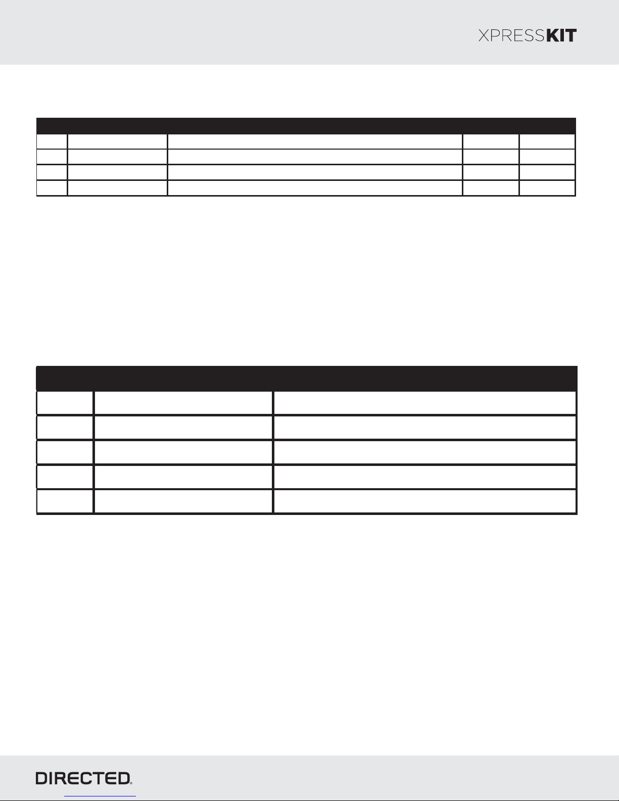
Button(s)
Actions
Press & hold for 1 s econd to loc k.
Press & hold for 1 s econd to unloc k.
Press & hold for 1 s econd to remote
start.
Press & hold for 5 s econds to activate
the trunk release (optional).
Press once, then to activate the
right sliding door.
Press 3 times, then to activate
the left sliding door.
Press once, then to reset the
remote starter runtime.
List of Available Commands
x1 +
x3 +
x1 +
Note that the information below is for Viper, Clifford and Python models. Icons and
commands may differ depending on the remote brand and model purchased. Refer
to your authorized installation center for more information.
 Loading...