

Directed SMARTASTART VSM300, SMARTASTART DSM300, SMARTASTART DSM350, SMARTASTART VSM350 Quick Reference Install Manual
Page 1
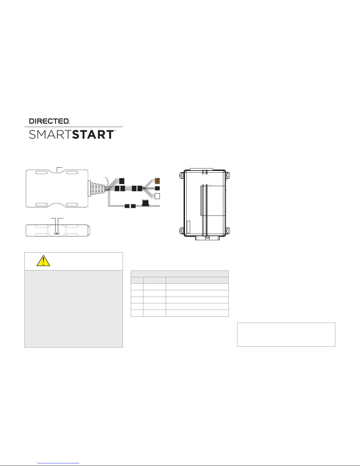
Quick Reference Install Guide
VSM300/350, DSM300/350
Red: +12V **
Black: Ground **
Fuse
ESP (3 pin, blk)
ESP (4 pin, brn)
or
2 pin
4 pin
Green LED
Data Connection
Amber LED
Network Status
5 pin Analog Cable
(see table)
3-way
Cable Adapter
Conguration Wires
Gray & White
D2D (4 pin, wht)
CPU1
NOTE: The appearance and connector/port
arrangement on the analog or digital system
being installed system may dier from the
example shown.
SmartStart Module
(Top view)
Directed System
(Top view)
LED’s
** Do not connect power and ground when using SmartStart
in a D2D conguration or damage may occur.
SmartStart Module (Side view, Top down)
INSTALLATION CAUTIONS
The white plug on the 3-way cable adapter
is ONLY for use with digital platforms such as
DBALL2, DBALL2PRo, 4X10 and 5X10.
For some older analog systems with combined
4-pin ESP/D2D ports, you CANNOT use an interface module in D2D mode when using a SmartStart module. You must use W2W on the bypass
module.
DO NOT connect the black 3-pin ESP connector
to white Door Lock port on Directed systems.
There should NEVER be more than one data plug
connected from the 3-way cable adapter.
Wiring Schematic
5-pin Analog Cable*
Pin # Wire Color Connection/Description
1 White/Blue
(-) RS (Remote Start)/AUX output
2 Brown
(-) Factory horn/Alert input
3 Green
(-) Lock Output
4 Blue
(-) Unlock Output
5 Red/White
(-) Trunk/AUX output
* NOTE: The analog output wires are only active if the
device has been configured for Analog Wire mode in the
installation portal.
Installation Procedure
This product is compatible with most Directed digital systems, analog systems with ESP2/D2D data
ports, and many Autostart and AstroStart systems
with pager ports and D2D ports.
Please read the following before proceeding.
1. Customer Information required:
• Record the customer information requested in step 4a of this procedure. The module Air ID # is provided on a sticker which
should be affixed to the space provided in
the user’s guide.
This information is required for final verification/activation of the VSM300/350 or
DSM300/350.
2. Installation Points:
• Install and test the security/remote start
or digital system first using the associated
guides and wiring diagram. When adding SmartStart to an existing system, verify it is fully functional before installing the
SmartStart module.
• Mount the SmartStart module as high as
possible in the vehicle with the engraved
side facing upward (for all devices).
Mount with minimal obstructions that can
affect communications and within reach
of the main Directed system using the provided cables (do not extend).
The module's signal strength (RSSI) can be viewed in the
activation portal after a successful transmission test.
-50 to -90 dB
-91 to -100 dB
> -100 dB
= good signal strength
= borderline/inconsistent signal strength
= weak, insufficient signal strength
QRNDSM350 2015-03
Page 2
2
© 2015 Directed. All rights reserved.
3. Install the VSM300/350 or DSM300/350 using the information in the wiring diagram and
the following steps.
a. Configuration Wires: Connect the loose
gray or white configuration wire(s) to
match the desired application (see the following chart).
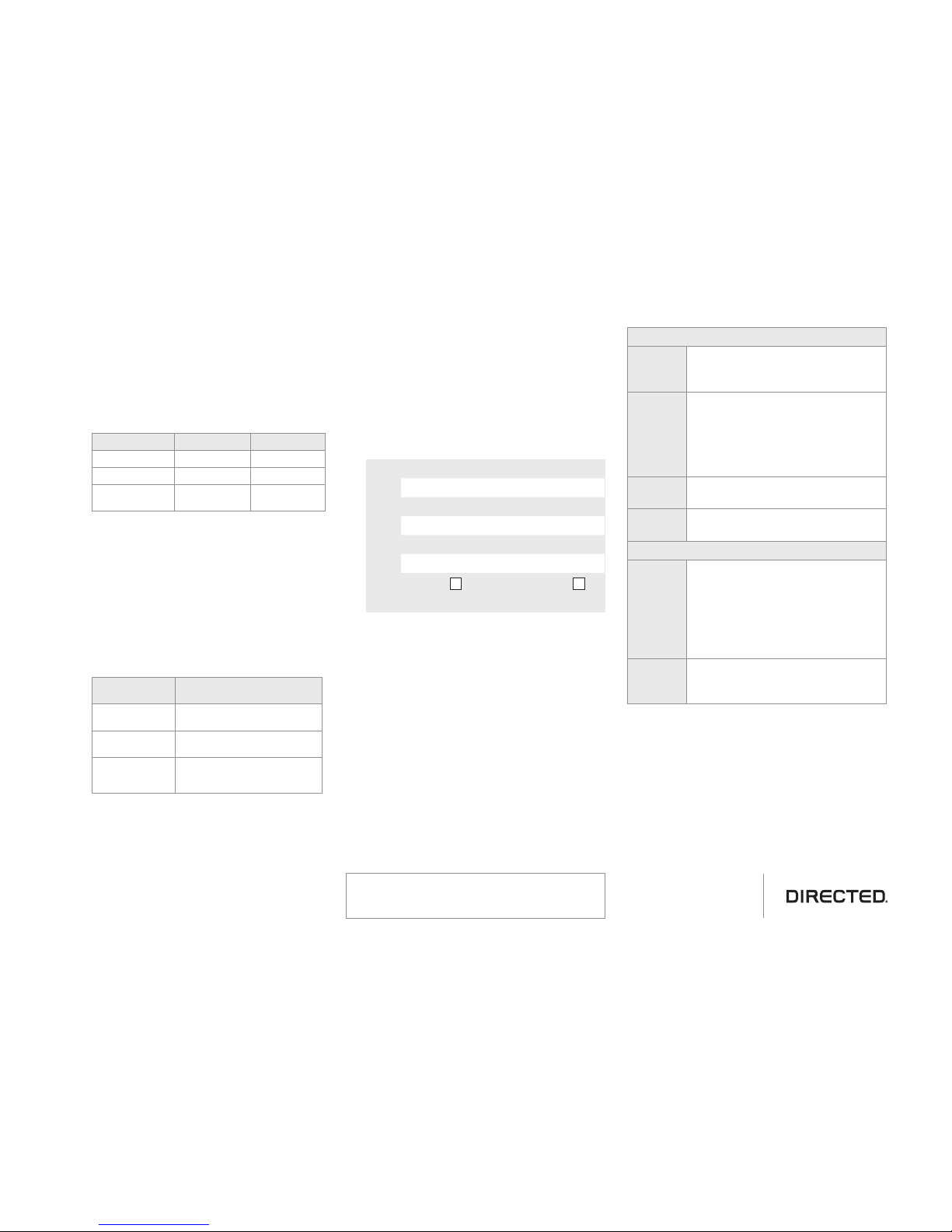
Configuration Wires Chart
MODE GRAY WIRE WHITE WIRE
ESP2* No Connection No Connection
D2D, RSR/RXT** GND No Connection
Autostart/AstroStart
No Connection GND
* Directed systems for Viper, Python,
Clifford, Avital and Automate.
** Directed digital systems.
b. Connect the serial data cable and adapt-
er to the correct port of the main module.
Use the following chart to determine which
connection is required for the application
being used.
3-way Cable Adapter Chart
Cable Adapter
Connector
Cable Adapter Application
ESP 4-pin Brown Use in systems that have one
port for D2D and ESP2
ESP 3-pin Black Use in systems that have a sepa-
rate port for D2D and ESP2
D2D 4-pin White Use in digital systems such as
DBALL2, DBALL2Pro, 4X10,
5X10
c. Complete the main power connections, if
required (see ** note in wiring diagram
on previous page).
d. When power is connected, the module
begins an initialization procedure that
may take several minutes. During this
procedure, progress is reported via the
flashing Amber/Green LEDs on the side of
the SmartStart module. When both LEDs
turn on solid, the initialization procedure
is completed (See LED Status Chart for a
description of the various LED states).
4. Verify and Activate the SmartStart module:
The following steps need to be performed
for the Verification/Activation of the Directed
SmartStart module.
a. Collect Customer Information:
Customer's E-mail Address:
Customer's mobile phone #
Record Module ID # here:
New Account: Existing Account:
b. Log on to: www.directechs.com, and click
on the SmartStart Activation link.
c. Follow the on-screen directions to activate
and test a SmartStart device. If this is the
customer’s first SmartStart system, you will
be prompted to enter their information as
collected in step 4a.
d. Set configuration for commands to match
the installed application.
e. Test the SmartStart system from the web-
site using the supplied function links.
f. The customer is sent log-in information via
e-mail. After logging into the site at:
www.mysmartstart.com, they must select
and pay for the service plan in order to
start using the system.
LED Status Chart
Amber LED
Off No cellular communication. Check
connections such as module harness.
Flashing
Slowly
The module is seeking cellular
system communication. If no cell
coverage is available the Amber
LED continues to flash slowly, move
the vehicle to a location with better
reception.
Flashing
Quickly
The module is negotiating with a
cellular system.
On Solid Communication successfully estab-
lished.
Green LED*
Off Communication not established with
the remote start main unit or no
serial device is connected. Check
connection at the Bitwriter port,
once connected properly the LED
turns on after resetting the power to
the SmartStart module.
On Solid Communication successfully es-
tablished with the remote start or
Directed digital systems.
* The green LED does not light if connected to Au-
tostart/AstroStart systems with pager ports, or in
standalone mode.
Additional information
can be found at:
www.directechs.com
Notes: SmartStart response time can vary depending on cel-
lular coverage and network congestion.
Operating temperature range: -30°C to + 70°C.
 Loading...