

Page 1

Installation Guide
Security and Remote Start
This product is intended for installation by a professional
installer only! Attempts to install this product by a person other than a
trained professional may result in severe damage to a vehicle’s electrical
system and components.
© 2012 Directed. Vista, CA
N5303 2012-01
N5103 2012-01
Page 2
Bitwriter®, Code Hopping™, Doubleguard®, ESP2™, FailSafe®,
Ghost Switch™, Learn Routine™, Nite-Lite®, Nuisance Prevention®
Circuitry, Revenger®, Silent Mode™, Soft Chirp®, Stinger®,
Valet®, Vehicle Recovery System®, VRS®, and Warn Away® are all
Trademarks or Registered Trademarks of Directed Electronics.
The Bitwriter® (p/n 998U)
requires chip version 2.7 or
newer to program this unit.
The 3-pin to 4-pin adapter cable is also required.
(included with 998U v 2.6 and above).
Bitwriters with date code of 6A or older require an IC upgrade (p/n
998M). Some Bitwriters with a date code of 6B do not require the IC
upgrade. Refer to Tech Tip # 1112 for more information.
Page 3

Contents
Warning! safety first ..........................................................................................4
Wiring Diagram ...............................................................................................5
Wiring connections ...........................................................................................5
Main Harness (H1), 12-pin connector..........................................................5
H2 Harness, 6-pin connector ......................................................................5
Remote Start ribbon harness* .....................................................................6
Heavy gauge relay satellite ........................................................................6
Relay satellite 4-pin connector ....................................................................6
H3 Harness Remote Start, 5-pin connector ..................................................6
H4 AUX 4/Horn, 2-pin connector ...............................................................6
Door Lock, 3-pin connector ........................................................................6
Adjusting the Sensor ..........................................................................................7
Tachometer settings ...........................................................................................7
Tach Learning ...........................................................................................7
Virtual Tach ..............................................................................................7
Programming jumpers ........................................................................................7
Tach threshold On/Off ..............................................................................8
Light flash (+) / (-) polarity .........................................................................8
Transmitter/receiver Learn Routine™ ....................................................................8
Transmitter configurations ...................................................................................9
System features learn routine ..............................................................................9
Feature menus and descriptions ........................................................................10
Menu 1 - Basic ......................................................................................10
Menu 1 - Descriptions .............................................................................10
Menu 2 - Advanced ...............................................................................12
Menu 2 - Descriptions ..............................................................................12
Menu 3 - Remote start ............................................................................14
Menu 3 - Descriptions ..............................................................................14
Security features disable/enable .......................................................................15
Red 4-pin port, Bitwriter/ESP2 or D2D programming ..........................................15
Bitwriter - Only Options ...................................................................................16
Bitwriter feature descriptions ....................................................................16
Long term event history ....................................................................................17
Table of zones ................................................................................................17
Remote Start shutdown diagnostics ....................................................................17
Troubleshooting: Alarm ....................................................................................18
Troubleshooting: Remote Start ...........................................................................18
Page 4

Warning! safety first
The following safety warnings must be observed at all times:
• Due to the complexity of this system, installation of this product must only be performed by an authorized Directed Electronics dealer.
• When properly installed, this system can start the vehicle via a command signal from the remote control. Therefore, never operate the
system in an area that does not have adequate ventilation.
The following precautions are the sole responsibility of the user; however, authorized Directed Electronics dealers should:
• Never use a test light or logic probe when installing this unit. Always use a multimeter.
• Never operate the system in an enclosed or partially enclosed area without ventilation (such as a garage).
• When parking in an enclosed or partially enclosed area or when having the vehicle serviced, the remote start system must be disabled
using the installed toggle switch. It is the user’s sole responsibility to properly handle and keep out of reach from children all remote controls
to assure that the system does not unintentionally remote start the vehicle.
• USER MUST INSTALL A CARBON MONOXIDE DETECTOR IN OR ABOUT THE LIVING AREA ADJACENT TO THE VEHICLE. ALL
DOORS LEADING FROM ADJACENT LIVING AREAS TO THE ENCLOSED OR PARTIALLY ENCLOSED VEHICLE STORAGE AREA MUST
REMAIN CLOSED AT ALL TIMES.
Use of this product in a manner contrary to its intended mode of operation may result in property damage, personal injury, or death. Except
when performing the Safety Check outlined in this installation guide, (1) Never remotely start the vehicle with the vehicle in gear, and (2) Never
remotely start the vehicle with the keys in the ignition. The user is responsible for having the neutral safety feature of the vehicle periodically
checked, wherein the vehicle must not remotely start while the car is in gear. This testing should be performed by an authorized Directed Electronics dealer in accordance with the Safety Check outlined in this product installation guide. If the vehicle starts in gear, cease remote start
operation immediately and consult with the user to fix the problem immediately.
After the remote start module has been installed, test the remote start module in accordance with the Safety Check outlined in this installation
guide. If the vehicle starts when performing the Neutral Safety Shutdown Circuit test, the remote start unit has not been properly installed. The
remote start module must be removed or properly reinstalled so that the vehicle does not start in gear. All installations must be performed by an
authorized Directed Electronics dealer.
OPERATION OF THE REMOTE START MODULE IF THE VEHICLE STARTS IN GEAR IS CONTRARY TO ITS INTENDED MODE OF OPERATION.
OPERATING THE REMOTE START SYSTEM UNDER THESE CONDITIONS MAY RESULT IN PROPERTY DAMAGE OR PERSONAL INJURY.
IMMEDIATELY CEASE THE USE OF THE UNIT AND REPAIR OR DISCONNECT THE INSTALLED REMOTE START MODULE. DIRECTED ELECTRONICS WILL NOT BE HELD RESPONSIBLE OR PAY FOR INSTALLATION OR REINSTALLATION COSTS.
IMPORTANT! This product is designed for fuel-injected, automatic transmission vehicles only. Installing it in a standard transmission vehicle is
dangerous and is contrary to its intended use.
Page 5
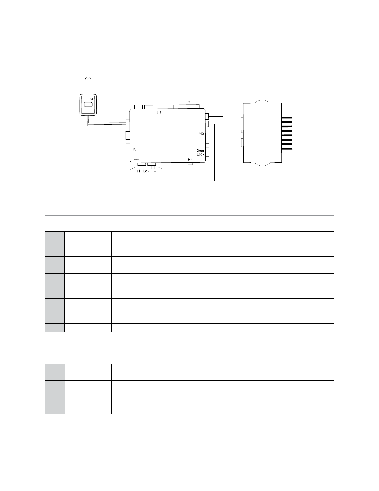
Wiring Diagram
Control
Center
Antenna
LED
Button
Shock Sensor port
Bitwriter
D2D port
Remote
Start port
To Remote
Start port
H
Relay
satellite port
Jumper
tachometer
Jumper
light ash
Control Center button input (use blue 2-pin
connector from Control Center cable)
Control Center LED output (use white 2-pin
connector from Control Center cable)
Wiring connections
Main Harness (H1), 12-pin connector
RED/WHITE (-) 200mA AUX TRUNK RELEASE OUTPUT
H1/1
RED (+) CONSTANT POWER INPUT
H1/2
BROWN (+) SIREN OUTPUT
H1/3
H1/4
BLACK (-) CHASSIS GROUND INPUT
H1/5
VIOLET* (+) DOOR TRIGGER INPUT, ZONE 3
H1/6
BLUE (-) INSTANT TRIGGER INPUT, ZONE 1
H1/7
GREEN* (-) DOOR TRIGGER INPUT, ZONE 3
H1/8
BLACK/WHITE (-) 200mA DOMELIGHT SUPERVISION OUTPUT
H1/9
WHITE/BLUE (-) REMOTE START ACTIVATION INPUT
H1/10
WHITE (+)/(-) SELECTABLE LIGHT FLASH OUTPUT
H1/11
ORANGE (-) 500mA GROUND WHEN ARMED OUTPUT
H1/12
* The door trigger wire will still need to be connected if the system is programmed with security features OFF to allow the system to enter the
programming modes.
NOT USED
H2 Harness, 6-pin connector
LIGHT BLUE (-) 200mA SECOND UNLOCK OUTPUT
H2/1
WHITE/BLACK (-) 200mA AUX 3 OUTPUT
H2/2
VIOLET/BLACK (-) 200mA AUX 2 OUTPUT
H2/3
GREEN/WHITE (-) 200mA FACTORY ALARM REARM OUTPUT
H2/4
GRAY/BLACK (-) WAIT-TO-START INPUT
H2/5
LIGHT GREEN/BLACK (-) 200mA FACTORY ALARM DISARM OUTPUT
H2/6
© 2012 Directed. All rights reserved.
5
Page 6

Remote Start ribbon harness*
PINK/WHITE (-) 200mA PROGRAMMABLE IGN2/ACC2 RELAY TURN ON
1
YELLOW (+) IGNITION INPUT TO ALARM
2
PINK (-) 200mA IGNITION RELAY TURN ON
3
ORANGE (-) 200mA ACCESSORY RELAY TURN ON
4
PURPLE (-) 200mA STARTER RELAY TURN ON
5
ORANGE/BLACK (-) 500mA ANTI GRIND/GROUND WHEN ARMED OUTPUT
6
BLUE (-) 200 mA STATUS OUTPUT
7
*The ribbon harness connects to the heavy gauge relay satellite.
Heavy gauge relay satellite
PURPLE STARTER OUTPUT TO STARTER (STARTER SIDE)
H/1
GREEN STARTER INPUT FROM IGNITION SWITCH (KEY SIDE)
H/2
RED (+) 30A HIGH CURRENT 12V INPUT
H/3
ORANGE OUTPUT TO ACCESSORY CIRCUIT
H/4
RED (+) 30A HIGH CURRENT 12V INPUT
H/5
PINK OUTPUT TO PRIMARY IGNITION CIRCUIT
H/6
RED/WHITE (+) 30A HIGH CURRENT 12V INPUT
H/7
PINK/WHITE OUTPUT TO SECOND IGNITION/ACCESSORY CIRCUIT
H/8
Relay satellite 4-pin connector
BLUE (-) 200mA STATUS OUTPUT
1
ORANGE (-) 200mA ACCESSORY RELAY TURN ON
2
PURPLE (-) 200mA STARTER RELAY TURN ON
3
PINK (-) 200mA IGNITION RELAY TURN ON
4
H3 Harness Remote Start, 5-pin connector
BLACK/WHITE (-) NEUTRAL SAFETY SWITCH INPUT
H3/1
VIOLET/WHITE TACHOMETER INPUT WIRE
H3/2
BROWN (+) BRAKE SHUTDOWN INPUT WIRE
H3/3
GRAY (-) HOOD PIN SWITCH INPUT, ZONE 6
H3/4
BLUE/WHITE (-) 200 mA 2ND STATUS/REAR DEFOGGER - Latched Pulsed
H3/5
H4 AUX 4/Horn, 2-pin connector
ORANGE/BLACK (-) 200mA AUX 4 OUTPUT
H4/1
BROWN (-) 200 mA HORN OUTPUT
H4/2
Door Lock, 3-pin connector
LIGHT BLUE (-) UNLOCK OUTPUT
1
2
GREEN (-) LOCK OUTPUT
3
6
NOT USED
© 2012 Directed. All rights reserved.
Page 7

Adjusting the Sensor
Important! Make sure the vehicle is disarmed. The shock sensor sensitivity can be adjusted by using a trimmer tool to turn the potentiometer.
Adjusting the sensor:
1. Disarm the system, turn the ignition Off.
2. With the sensor mounted in its permanent location, locate the trim pot on the shock sensor module and using a trimmer tool:
• Turn the potentiometer clockwise for increased sensitivity or
• Turn it counterclockwise for decreased sensitivity
Note: You can test the new setting by cautiously impacting the vehicle with increasing intensity while noting the LED status on the shock
sensor. The LED turns on for a short duration for small impacts before turning off (indicating a warn-away trigger). The impact level required
to fully trigger the alarm is indicated when the LED remains on for a longer duration before turning off.
Tachometer settings
Tach Learning
To learn the tach signal:
1. Start the vehicle with the key.
2. Within 5 seconds, press and hold the control center button.
3. After 3 seconds the LED will light constant when the tach signal is learned.
4. Release the control center button.
Important: This unit can learn the tachometer with the analog input or through D2D
using an interface module. The unit confirms which source is used.
When programming tach learning with:
• Analog, the parking lights flash one time.
• D2D interface module, the parking lights flash twice
If the tachometer input on the system is connected to the vehicle, the D2D tachometer input will be ignored.
Virtual Tach
Note: Virtual tach is not recommended for diesel trucks
To program Virtual Tach:
1. After the install is complete, remote start the car.
2. If the car does not start on the first attempt, let the remote start attempt again.
3. Once the car starts, let it run until the parking lights come on.
4. When the parking lights come on, shut off the remote start with the remote - that’s it! Virtual Tach is programmed.
Virtual Tach handles disengaging the starter motor during remote starting – it does not address over-rev. If the customer wants to have the overrev protection capability, the tach wire must be connected. This may involve more installation shop charges than initially quoted.
Important: If the Virtual Tach mode over cranks or doesn't crank the vehicle long enough to start and run the
car, use the Bitwriter to add or subtract the starter output time. You can adjust the output time in increments
of 50msec of the learned time using the Bitwriter.
Programming jumpers
© 2012 Directed. All rights reserved.
7
Page 8

Tach threshold On/Off
In most cases, this jumper can be left in the Off position. Some new vehicles use less than 12 volts in their ignition systems. The unit may have
trouble learning the tach signal in these vehicles. Changing the jumper to the On setting changes the trigger threshold of the digital tach circuit
so that it will work with these type vehicles.
Light flash (+) / (-) polarity
The jumper is used to determine the light flash output polarity. In the (+) position, the onboard relay is enabled and the unit outputs (+)12V on
the WHITE H1/11 wire. In the (-) position, the on-board relay is disabled. The White H1/11 wire will supply a 200mA (-) output suitable for
driving factory parking light relays.
Note:
For parking light circuits that draw 10 amps or more, the internal jumper must be switched to a (-) light flash output. P/N 8617 or a
standard automotive SPDT relay must be used on the H1/11 light flash output harness wire.
Transmitter/receiver Learn Routine™
The system comes with transmitters that have been taught to the receiver. The receiver can store up to 4 different transmitter codes in memory.
Note:
When doing any programming with security features off, the horn function (feature menu 1
item 13) must be programmed as Siren function to get an audible confirmation from the unit.
If the learn routines have been programmed using the Bitwriter, they may have been locked. Before proceeding with reprogramming
the learn routines, they must be unlocked with the Bitwriter - this cannot be done manually with the control center button.
Note
:
The Bitwriter requires software v2.7. Bitwriters with date code of 6A or older require an IC upgrade (p/n 998M). Some Bitwrit-
ers with a date code of 6B do not require the IC upgrade, refer to Tech Tip # 1112 for more information.
The control center button, plugged into the blue port, is used for programming. There is a basic sequence to remember whenever programming
this unit: Door, Key, Choose, Transmit and Release.
1. Open a door.
2. Insert the key. Turn the ignition to the ON position. The heavy gauge pink wire must be connected.
3. Choose. Within 10 seconds, press and release the Control center button corresponding to the number of the desired function step listed
in the following table.
Once you have selected the function step, press the control center button once more and hold it. The LED flashes and the siren chirps to confirm
the selected functional step. Do not release the control center button.
Step Function
1
Auto Learn Standard Configuration (default)
The auto learn configuration will automatically set up the remote button configuration. Note: You cannot change the configuration
of the remote control buttons.
2
Delete remotes: This feature will erase all remotes from the memory of the system. This is useful in cases when a customer’s remote
is lost or stolen. Note: Does not reset the programmed features of the system or reset the Virtual Tach setting.
3
Reset Features: This resets all the features of the system to the factory default settings. Note: Does not delete the remotes from the
system or reset the Virtual Tach setting.
4
Virtual Tach Reset: Deletes all previously learned values for Virtual Tach, and on the next remote start sequence the unit will begin
virtual tach initialization. Note: The “Zap” feature on the Bitwriter does not reset the Virtual tach setting.
4. Transmit. While holding the Control center button, press the
has been successfully programmed or the selected feature has been reset. It is not possible to teach a remote control button to the system
more than once.
5. Release. Once the code is learned, or the feature reset, the Control center button can be released.
You can advance from programming one step to another by releasing the Control center button and tapping it to advance steps and then
holding it.
If you want to program Step 3 after programming Step 1, release the Control center button, press it twice and release it to advance to Step
3. Then press it once more and hold it. The siren chirps three times and the LED flashes three times to confirm it is ready to receive the code
from the transmitter.
Learn Routine is exited if:
button on the remote control. The siren chirps to confirm that the code
• Door is closed.
8
© 2012 Directed. All rights reserved.
Page 9

• The ignition is turned off.
• The control center button is pressed too many times.
• More than 15 seconds elapses between steps.
Transmitter configurations
The transmitters are programmed with the standard configuration by using the Auto Learn functions in the Transmitter/Receiver Learn Routine. For
more information about the remote control functions, see the Owners Guide.
System features learn routine
The System Features Learn Routine dictates how the unit operates. It is possible to access and change any of the feature settings using the control
center button. However, this process can be simplified by using the Bitwriter®. Any of the settings can be changed and then assigned to one of
four remote controls. This feature is called Owner Recognition. Each time that particular remote control is used to disarm the system, the assigned
feature settings will be recalled. Owner Recognition is only possible when programming the unit via the Bitwriter®.
If programming with the Bitwriter®, the learn routine can be locked or unlocked. If the learn routine has previously been locked, it must
be unlocked with Bitwriter® - this cannot be done manually with the control center button .
1. Open a door.
2. Ignition. Turn the ignition on, and then off.
3. Select menu. Press and hold the Control center button. the number of siren chirps indicates the menu number. 1 chirp indicates menu 1,
2 chirps-menu 2 and 3 chirps for menu 3. when the desired menu chirps are heard, release the control button.
4. Select a feature. press and release the control center button the number of times corresponding to the feature you wish to change. then
press and hold one more time to select the feature..
5. Transmit. The transmitter is used to select the desired setting. Pressing
changes the setting to the two chirp setting. For features with more than two options:
6. Release, the control center button.
Once a feature is programmed:
• Other features can be programmed within the same menu.
• Another menu can be selected.
• The learn routine can be exited if programming is complete.
changes the feature to the one chirp setting. Pressing
selects the options in ascending order.
To access another feature in the same menu:
1. Press and release the control button the number of times necessary to advance from the feature you just programmed to the next one you
want to program.
2. Then press the control button once more and hold it.
To select another menu:
1. Press and hold the control button.
2. After 3 seconds, the unit advances to the next menu and the siren chirps, indicating which menu has been accessed.
The learn routine is exited when:
• The door is closed.
• The ignition is turned on.
• The Control center button is pressed too many times.
• More than 20 seconds elapses between programming steps.
One long siren chirp indicates that the Learn routine has been exited.
© 2012 Directed. All rights reserved.
9
Page 10

Feature menus and descriptions
The default settings are indicated in bold type. The number in parentheses indicates the number of times the siren chirps
Menu 1 - Basic
Menu
Item
1
One-chirp setting
Active Arming
Two-chirp setting
Passive arming
2
Arm/disarm chirps on
3
Ignition lock On
4
Ignition unlock On
5
Active locking only
6
Panic with ignition On
7
0.8 second door lock pulses (1)
8
Forced passive arming on
9
Automatic engine disable on
10
Armed When Driving (AWD) On
11
Code Hopping On
12
Horn Output Pulsed
13
Horn function Full Alarm Only (1)
14
Comfort Closure ON (1)
Arm/disarm chirps Off
Ignition lock Off
Ignition unlock Off
Passive locking
No panic with ignition On
3.5 (2), 0.4 (3) seconds
Forced passive arming off
Automatic engine disable off
AWD Off
Code Hopping off
Constant
Siren function - chirp length
20mS (2), 30mS (3), 40mS (4), 50mS (5)
Comfort Closure OFF (2)
Comfort Closure 2 (3)
The features of the system are described below. Features that have additional settings when programming with the Bitwriter® only, are indicated by the following icon:
Menu 1 - Descriptions
1. System Arming mode
1. Active: the transmitter must be used to arm the system
2. Passive Arm: after exiting the vehicle the system will automatically arm.
2. Arm/Disarm chirps
1.
On:
arm, disarm chirps are active
2. Off : arm, disarm chirps are defeated.
3. Ignition Lock
1.
Off:
the door lock output will not output when ignition is turned off.
2. On: The door lock output will activate when the ignition is turned o
4. Ignition Unlock
1. Off: the door unlock output will not output when ignition is turned on.
2. On: The door unlock output will activate when the ignition is turned on.
5. Active/Passive Locking:
If passive arming is selected in Feature 1-1, then the system can be programmed to either lock the doors when passive arming occurs, or only
lock the doors when the system is armed via the transmitter.
1. Active locking: The system will not lock the doors when it passively arms.
2. Passive locking: The system will lock the doors when it passively arms.
Note: Remember, when passive arming is selected, the unit will chirp 20 seconds after the last door is closed. The system does not actually arm
or lock the doors until 30 seconds after the door has been closed.
10
n
© 2012 Directed. All rights reserved.
Page 11

6. Panic With Ignition On:
1. Panic with ign On: the Panic output can be activated at any time
2. No panic with ign On : the Panic output can be activated only when the ignition is off
7. Door Lock Output Duration
1. 0.8 sec.: the door lock/unlock output pulses will be 800 mS in duration
2. 3.5 sec.: the door lock/unlock pulses will be 3.5 seconds in duration
3. 0.4 sec.: the door lock/unlock pulses will be 400 mS in duration
8. Forced Passive Arming:
1. On: forced passive arming will ensure that the system will passively arm, even if a zone is left open. Forced passive arming occurs one
hour after the ignition is turned off.
2. Off: the system will not passively arm if a zone is left open..
9. Automatic Engine Disable (AED)
1. On: the orange ground-when-armed output will activate 30 seconds after the ignition is turned off. The LED will flash at half its normal
rate when the ignition is turned off to indicate that AED is active and will interrupt the starter in 30 seconds. AED does not occur in Valet
mode and can be bypassed using the emergency override procedure. The transmitter can be used to disarm AED, however, the system
must be armed and then disarmed, using the transmitter, to disarm AED.
2. Off: the orange ground-when-armed output will not activate 30 seconds after the ignition is turned off.
10. Armed While Driving (AWD)
1. On: the system can be armed with the ignition on. When armed, the ground-when armed is not active and the sensors are bypassed.
The door triggers will remain active.
Note: turning off the ignition will disarm the system.
2. Off: the system cannot be armed when the ignition is on..
11. Code Hopping®
• On/Off: The system uses a mathematical formula to change its code each time the transmitter and receiver communicate. This makes
the group of bits or "word" from the transmitter very long. The longer the word is, the easier it is to block its transmission to the unit.
Disabling the Code Hopping® feature lets the receiver ignore the Code Hopping® part of the transmitted word. As a result, the unit
may have better range with Code Hopping® off.
12. Horn Output
1. Pulsed: the horn honk output will be pulsed when the system is triggered.
2. Constant: the horn honk output will be constant when the system is triggered.
13. Horn Function
1. Full Alarm Only: the horn output will pulse only during full trigger events.
2. Siren Function 20/30/40/50 mS: The horn output will emulate the siren output with selectable chirp output timing to compensate for
OEM horn inefficiency.
14. Comfort Closure
1. Comfort Closure On: The door lock pulse (or 2nd pulse for double pulses) will remain on for 20 seconds.
2. Comfort Closure Off: Comfort Closure is defeated when arming.
3. Comfort Closure 2: 800 mS following the end of the door lock pulse (or 2nd pulse for double pulses); the door lock output will turn on
again for 20 seconds.
To test if the car has the comfort closure:
1. Insert the key into the drivers door key cylinder.
2. Turn the key to the lock position and hold for about 10 seconds. Some cars require that you turn the key once, release, and then
turn and hold into the lock position.
If Comfort closure is available, the windows (and in some cars the sunroof) close.
Important:
Comfort closure can only be used on cars that have the capability of closing the win-
dows (and on some cars the sunroof as well) with the key cylinder in the door.
© 2012 Directed. All rights reserved.
11
Page 12

Menu 2 - Advanced
Menu
Item
One-chirp setting
1
30 second siren duration
Two-chirp setting
60 second siren duration*
2
Nuisance Prevention Circuitry On
3
Progressive door trigger
4
Disarm from Valet, 1 pulse
5
Door trigger error chirp ON
6
Ignition controlled domelight On
7
Unlock output 1 pulse
8
Lock output 1 pulse
9
Factory disarm with trunk release ON
10
FAD function with Unlock (1)
11
FAD 1 pulse
12
AUX 2 validity (1)
13
AUX 2 Linking None (1)
14
AUX 3 validity (1)
15
AUX 3 linking None (1)
16
AUX 4 validity (1)
17
AUX 4 linking None (1)
*Additional settings using the Bitwiter®.
Nuisance Prevention Circuitry OFF
Instant door trigger
Disarm from Valet, 2-5 pulses
Door trigger error chirp OFF
Ignition controlled domelight OFF
Unlock output 2 pulses
Lock output 2 pulses
Factory disarm with trunk release OFF
Before Unlock (2), Remote Start only (3)
2 pulses
Latched (2), Latch reset with ignition
(3), 30-secs timed (4), 60-secs (5), 90-secs (6)*
Arm (2), Disarm (3), Remote Start (4)
Latched (2), Latch reset with ignition
(3), 30-sec. timed (4)60sec(5)90sec(6)*
Arm (2), Disarm (3), Remote Start (4)
Latched (2), Latch reset with ignition (3), 30-sec. timed (4) 60sec (5) 90
(6)*
Arm (2).Disarm (3), Remote Start (4)
Menu 2 - Descriptions
1. Siren Duration:
1. 30sec: the siren output for full trigger activations and Panic mode is 30 seconds
2. 60sec: the siren output for full trigger activations and Panic mode is 60 seconds
2.- Nuisance Prevention® Circuitry (NPC)
1. On: sensors that trigger excessively will be defeated until they have been stable for more than one hour.
2. Off: sensors will not be defeated if triggered excessively
3. Progressive Door Trigger
1. On: When the door is opened with the system armed, the siren will chirp 10 times prior to the full triggered sequence.
2. Off: The full siren output will occur the moment the door is opened.
4. Valet Disarm Pulse Count
• 1-5: sets the number of presses (1-5) on the Control Center Button required to override the alarm system.
5. Door Trigger error Chirp
1. On: if the door trigger is active when arming, the siren will emit an additional chirp as an alert
2. Off: an active door trigger when arming will not create an alert output.
6. Ign-controlled Dome light
1. On: the system will turn on the dome light for 30 seconds when the ignition is turned off.
2. Off: the system does not turn on the dome light when the ignition is turned off.
NOTE: the dome light supervision option must be installed.
12
© 2012 Directed. All rights reserved.
Page 13

7. Unlock Output
1. 1 pulse: The unlock output pulses once
2. 2 pulses: The unlock output pulses twice.
8. Lock Output
1. 1 pulse: The lock output pulses once
2. 2 pulses: The lock output pulses twice
9. Factory Alarm Disarm w/Trunk Release
1. On: the Factory Alarm Disarm wire will pulse as programmed when the Trunk release output is activated.
2. Off: the Factory Alarm Disarm wire will not pulse when the Trunk release output is activated.
10. Factory Alarm Disarm—
1. With Unlock: In the default setting the factory alarm is disarmed any time the button(s) controlling Unlock is pressed and when remote
start is activated.
2. Before Unlock: output to disarm the factory alarm activates before unlock and when remote start is activated.
3. Remote Start Only: output disarms the factory alarm before remote start is activated.
11. Factory Alarm Disarm Pulses
• Single, Double: Selectable for a single or double-pulse for the vehicle’s factory alarm disarm input requirements.
12. AUX 2 Validity
This wire provides a (-) 200mA output whenever the transmitter button(s) controlling AUX 2 is pressed. This output can be programmed to provide
the following types of outputs:
1. Validity: Output that will send a signal as long as the transmission is received.
2. Latched: Output that will send a signal when the AUX button is pressed and will continue until the same button(s) is pressed again.
3. Latched, reset with ignition: Similar to the latched output, this type of output turns on the first time the AUX button is pressed and turns off
the next time the same button is pressed. This type of output additionally stops and resets whenever the ignition is turned on and then off.
4. 30 (60 or 90) second timed: Output that will send a continuous signal for 30,60 or 90 seconds.
•
Note: All auxiliary channel timed outputs can be programmed using the Bitwriter® (1-90 seconds).
13 AUX 2 Linking None
1. Linking None: Feature not enabled.
2. Arm: When programming to validity or timed output this can be programmed to activate when arming
3. Disarm: When programming to validity or timed output this can be programmed to activate when disarming
4. Remote Start: When programming to validity or timed output this can be programmed to activate when remote starting with the transmitter.
2-14 Aux 3 Validity(1)/Latched(2)/Latched Reset With Ignition(3)/30(4),60(5) And 90(6) Sec Timed Output:
AUX 3 can be programmed for these output configurations. The unit is set to the default validity output. To change the configuration, use the
two-chirp setting to toggle through the different configurations. Refer to feature 12 for additional detail.
2-15 Aux 3 Linking None(1)/Arm(2), Disarm(3), Remote Start(4): Refer to feature 13 for additional detail.
2-16 Aux 4 Validity(1)/Latched(2)/Latched Reset With Ignition(3)/30, 60 And 90 Sec Timed Output:
AUX 4 can be programmed for these output configurations. The unit is set to the default validity output. To change the configuration, use the
two-chirp setting to toggle through the different configurations. Refer to feature 12 for additional detail.
2-17 Aux 4 Linking None(1)/Arm(2), Disarm(3), Remote Start(4): Refer to feature 13 for additional detail.
© 2012 Directed. All rights reserved.
13
Page 14

Menu 3 - Remote start
Menu
Item
One-chirp setting
1
Engine checking: Virtual Tach
Two-chirp setting
Voltage(2), OFF(3), Tachometer(4)
2
Remote start runtime: 12 mins
3
Parking light output: Flashing Constant
4
Cranking time: 0.6 sec
5
Activation pulse 1
6
2nd Ignition/Acc output: Ignition
7
Acc state during wait-to-start Off
8
2nd status output: Normal
9
Anti grind: On
10
Diesel timer: Wait-to-Start input
11
Timer mode run time: 12 min
12
Timer mode: Timed starts
13
Short run (turbo): 1 min
24 min, 60 min*
0.8, 1.0, 1.2, 1.4, 1.6, 1.8, 2.0, 4.0 second
2
Accessory
On
Rear defogger: latch 10 min.
rear defogger pulse
Off
Timed 15 , 30 ,45 seconds*
3, 6, 9, min*
Temp starts
3,5, 10 min
*Additional settings using the Bitwriter®
Menu 3 - Descriptions
1. Engine Checking Mode
1. Virtual Tach: battery voltage drop/rise during cranking determines when the starter output is released. During runtime, constant voltage
level is monitored to determine if the engine is running
2. Voltage: starter output during cranking is a programmed duration (Set in Cranking Time). During runtime, constant voltage level is
monitored to determine if the engine is running
3. Off: starter output during cranking is a programmed duration (Set in Cranking Time). The remote start will keep the ignition/accessories
active for the programmed runtime whether the engine is running or not
4. Tachometer: tachometer input signal during cranking and runtime to determine when the starter output is released and if the engine is
running.
2. Run Time
• 12/24/60 minutes: sets engine runtime during normal remote start operations
3. Parking Light Output
1. Flashing: the lights will pulse on/off during remote start
2. Constant: the lights will turn on solid during remote start.
4. Cranking Time
• 0.6/0.8/1.0/1.2/1.4/1.6/1.8/2.0/4.0 seconds: determines the starter output duration during cranking for the ‘Voltage’ and the
‘Off’ Engine Checking Mode options
5. Activation Pulse Count
• 1/ 2 pulses: sets the number of remote control commands received or Activation Input required to activate and de-activate remote start
6. 2nd Ignition/Accessory Output:
• This will allow the PINK/WHITE to be used as a 2nd ignition or an accessory. The default is 2nd ignition.
7. Accessory State During Wait-To-Start Off/On:
• This feature will allow the selection of the accessory output to be ON or OFF during wait-to-start.
8. Status 2 Output (Dark Blue H2/10 wire)
1. Status Normal: the output will activate before the ignition outputs turn on, and de-activate after they turn off during remote start
14
© 2012 Directed. All rights reserved.
Page 15

2. Latch rear defogger: the output activates 10 seconds after start if the interior temperature is below 55F. It turns off after 10 minutes or
upon remote start off
3. Pulse rear defogger: the output activates (for 800mS) 10 seconds after start if the interior temperature is below 55F.
9. Anti-grind Output
• On/Off: With the anti-grind On (default) the ground-when-armed output will be active during remote start operation. If accessories such
as a voice module or window module are added to the unit, it may be necessary to program this feature off..
10. Diesel Start Delay
1. Wait-to-start input: (-) input on the Grey/black (H2/7) WTS wire will delay the starter output until the ground ceases.
2. Timed 15/30/45 seconds: delays the starter output per the selected option, the WTS wire does not function.
11. Run Time (Timer Mode)
• 12, 3, 6, 9 Minutes: Selects the time in minutes that the system will operate the engine until the system "times out". This is the maximum
operation period and the system may be shut down using a shutdown at any time. Using the Bitwriter®, the run time can be programmed for any duration from 1-16 minutes.
12 Timer Mode
• Timed Starts/Temperature Starts: The system will start every 3-hours (a maximum of 6 times) until canceled by the brake, hood, turning
on the ignition, or neutral safety shut-down wires. The temperature start mode will not start the vehicle unless the interior temperature of
the vehicle is less than 0 degrees F. The temperature start mode will exit after 18 hours.
13 Short Run/Turbo
• 1/3/5/10 Minutes: When turbo mode is activated, the engine will run for the duration set per the selected option.
Security features disable/enable
The system has the ability to function as a security/remote start system or keyless/remote start system by enabling or disabling security. The
default setting is Enabled.
To program the feature.
1. Open a door.
2. Turn the ignition on, then off.
3. Press and hold the valet button until the LED flashes 3 times and the siren (if connected) chirps 3 times.
4. Release the control center button.
Note: If the valet button is released and then pressed again, the system will enter the features programming menus.
5. Within 15 seconds, simultaneously press the
6. The siren (if connected) will chirp and the parking lights will flash as listed below
1 flash/chirp: Security features disabled
2 flashes/chirps: Security features enabled
Security Features Disabled will disable all security operations of the system, including but not limited to those listed below:
• Multi Level Arming
• Sensor Warn-away
• Full Trigger Operation
and
buttons of a programmed remote control.
Red 4-pin port, Bitwriter/ESP2 or D2D programming
The Red 4-pin plug may be configured as a Bitwriter/ESP2 or D2D port.
The factory default is Bitwriter/ESP2 mode.
To use as D2D mode follow the below steps:
1. Make sure White/Blue activation wire is grounded.
2. Power the unit up. The system LED flashes for 5 seconds to confirm D2D mode change.
3. Remove the White/Blue wire from ground.
To change from D2D to Bitwriter/ESP2 mode:
1. Make sure the White/Blue activation wire is grounded.
2. Power the unit up, the system LED turns on solid for 5 seconds to confirm Bitwriter/ESP2 mode change.
3. Remove the White/Blue wire from ground.
The procedure can be repeated to toggle from one mode to the other.
Important: If you power up the system with the White/Blue activation wire ungrounded, the system LED
will come on solid for 5 seconds indicating the system is in Bitwriter/ESP2 mode.
© 2012 Directed. All rights reserved.
15
Page 16

Bitwriter - Only Options
If programming with the Bitwriter®, the learn routine can be locked or unlocked. If the learn routine has previously been locked, it must
be unlocked with Bitwriter® - this cannot be done manually with the control center button.
The Bitwriter® gives you access to a wider range of system options. These features and the adjustments that may be programmed are
described in the table below.
Menu
Feature Default Options
Item
1 Siren Duration
2 Aux 2 Timed Output
3 Aux 3 Timed Output
4 Aux 4 Timed Output
5 Engine Runtime
6 Diesel Start Delay
7 Timer Mode Runtime
8 Virtual Tach Fine Tune
9 Transmitter Programming
10 Feature Programming
30 sec.
30 sec.
30 sec.
30 sec.
12 min.
15 sec.
12 min.
Not initialized
Unlocked
Unlocked
Note: The “Zap” feature on the Bitwriter does not reset the Virtual tach or security features enabled/disabled settings
Bitwriter feature descriptions
1-180 sec.
1-90 sec.
1-90 sec.
1-90 sec.
1-60 min.
1-90 sec.
1-16 min.
0-1000 in 50 millisecond increments
Locked
Locked
1. Siren duration:
Sets the siren output for full trigger activations from 1-180 seconds.
2. Aux 2 timed output:
Sets the output duration in 1 second intervals up to 90 seconds.
3. Aux 3 timed output:
Sets the output duration in 1 second intervals up to 90 seconds.
4. Aux 4 timed output:
Sets the output duration in 1 second intervals up to 90 seconds.
5. Engine runtime:
Sets engine runtime during normal remote start operations from 1-60 minutes.
6. Diesel start delay:
Sets the delay before engine crank in 1 second intervals from 1- 90 seconds for diesel engine vehicles.
7. Timer mode runtime:
Sets the duration of runtime when the engine is started by the Timer Mode from 1-16 minutes.
8. Virtual tach fine tune:
Adds or subtracts crank time in VirtualTach mode in order to overcome engine types that short crank or over-crank on the first start attempt.
9. Transmitter programming:
Locks and unlocks the user’s ability to enter the remote control/Reset menu and manually change any functions using the Control Center
10. Feature Programming:
Locks and unlocks the user’s ability to enter the feature menus and manually change the main unit programming using the Control Center.
16
© 2012 Directed. All rights reserved.
Page 17

Long term event history
The system stores the last two full triggers in memory. These are not erasable. Each time the unit sees a full trigger, the older of the two triggers
in memory will be replaced by the new trigger. To access long term event history:
1. With the ignition off, press and hold the Control center button.
2. Turn on the ignition.
3. Release the Control center button.
4. Press and release the Control center button within 5 seconds. The LED will flash in groups indicating the last two zones that triggered the
unit. The LED will flash for one minute or until the ignition is turned off.
NOTE: The Warning Zone triggers are not stored to memory and will not be reported.
Table of zones
Use the Table of Zones diagnostic function to see which input triggered the system. It can also help to determine which input to use when connecting optional sensors and switches.
Zone No. Trigger Type
1
Instant Trigger BLUE (H1/7)
2
Multiplexed Shock Sensor Input Mux BLUE sensor port wire.
3
Door Trigger GREEN (H1/8) and VIOLET (H1/6).
4
Multiplexed Shock Sensor Input Mux GREEN wire
5
Ignition
6
Hood Trigger GRAY on the 6-pin shutdown harness
Input Description
Yellow ribbon harness wire
Remote Start shutdown diagnostics
To perform shutdown diagnostics:
1. With the ignition OFF, press and hold the Control center button.
2. Turn the ignition ON and then back OFF while holding the Control center button.
3. Release the Control center button.
4. Press and release the Control center button. The LED flashes to report the last shutdown for one minute or until the ignition is turned on,
as shown in the following table:
LED Flashes Shutdown Mode
1 Timed out
2 Over-rev shutdown
3 Low or no RPM, low battery (for voltage and virtual tach modes)
4 Transmitter shutdown (or optional push button)
5 (-) Hood Shutdown (H3/4 GRAY)
6 (+) Shutdown (H3/3 BROWN)
7 (-) Neutral safety shutdown (H3/1 BLACK/WHITE)
8 Wait-to-start timed out
© 2012 Directed. All rights reserved.
17
Page 18

Troubleshooting: Alarm
Shock sensor doesn’t trigger the alarm:
1. Was the onboard shock sensor adjusted before it was mounted? If so re-adjust the sensor.
2. Has the onboard shock sensor been turned off? The sensor has the ability to be turned off when adjusting.
3. Has the NPC® system been triggered? If so, you hear 5 chirps when disarming. To check this, turn the ignition key on and off to
clear the NPC® memory, and then retest the shock sensor. For a detailed description of NPC®, see Nuisance Prevention Circuitry
section of the owners guide.
Door input does not immediately trigger full alarm. Instead, chirps are heard for the first 3 seconds:
• That’s how the progressive two-stage door input works! This is a feature of this system even if the door is instantly closed again, the
progression from chirps to constant siren continues.
Closing the door triggers the system, but opening the door does not:
• Have you correctly identified the type of door switch system? This happens often when the wrong door input has been used.
System does not passively arm until it is remotely armed and then disarmed:
1. Is passive arming programmed ON?
2. Are the door inputs connected? Is the H1/7 blue wire connected to the door trigger wire in the vehicle? Either the H1/8 green or
the H1/6 violet should be used instead.
Door input does not respond with the progressive trigger, but with immediate full alarm:
• Does the Status LED indicate that the trigger was caused by the shock sensor? (See Table of Zones section of this guide.) The shock
sensor, if set to extreme sensitivity, may be detecting the door unlatching before the door switch sends its signal. Reducing the sensitivity can solve this problem.
Door locks operate backwards.
• This unit has easily-reversed lock/unlock outputs. Recheck wire connections to see if you have reversed these.
Troubleshooting: Remote Start
The remote start will not activate the remote start
1. Is the neutral safety switch plugged in and turned on?
2. Is the remote programmed to the system?
3. Can the remote start be activated manually by applying a ground pulse to the H1/10 White/Blue wire?
4. Check the harnesses and their connections. Make sure that the harnesses are completely plugged into the remote start module. Make
sure there are good connections to the vehicle wiring.
5. Check voltage and fuses on the main 12-pin harness and on the heavy gauge remote start harness.
The remote start will activate, but the starter never engages.
1. Check for voltage on the purple starter wire two seconds after the remote start becomes active. If there is voltage present, skip to
Step 5. If there is not voltage present, advance to Step 2.
2. Check the 30A fuses.
3. If the gray/black wait-to-start wire is detecting ground upon activation, the starter will not crank.
4. Is the tach wire connected? If so disconnect it and remote start the vehicle to see if the purple wire sends out voltage. If you get volt-
age you will need to go to an alternate tach source, the tach wire you are currently on has a voltage spike upon ignition power up
which can cause the remote start to not send out the crank voltage.
5. Is the vehicle a Chrysler or GM with a multiplexed starter wire? The vehicle will not crank if the resistance is incorrect on the multi-
plexed accessory/starter wire.
6. Is the vehicle a GM? If so the Brown 2nd accessory needs to be powered up on some of the vehicles for the vehicle to crank.
7. Make sure the purple starter wire is connected on the starter side of the optional starter kill/anti-grind relay.
8. Does the vehicle have an immobilizer? Some immobilizer systems will not allow the vehicle to crank if active.
9. Check connections. The heavy gauge remote start input wires on the heavy gauge 10-pin connector should have a solid connection.
“T-taps” or “scotch locks” are not recommended.
The vehicle starts, but immediately dies.
1. Does the vehicle have an immobilizer? The vehicle’s immobilizer can cut the fuel and/or spark during unauthorized starting attempts.
2. Is the remote start programmed for virtual tach or voltage sense? If so, the crank time may not be set high enough. Voltage sense
will not work on some vehicles.
3. Is the remote start in tach mode? If so has the tach been programmed to the system?
4. Check diagnostics. Sometimes a shutdown will become active during cranking or just after cranking.
The vehicle starts, but the starter keeps running.
1. Is the system programmed for engine checking off or virtual tach voltage sense? When programmed for either of these features, the
engine cranks for the pre programmed crank time regardless of how long it takes for the vehicle to actually start. Adjust to a lower
18
© 2012 Directed. All rights reserved.
Page 19

cranking time.
2. Was the Tach Learn successful? The LED must light solid and bright to indicate a successful learn.
3. Make sure that there is a tach signal at the purple/white tach input wire of the remote start. If there is not a tach signal, recheck the
connection to the vehicle’s tach wire and make sure the wire is not broken or shorted to ground leading to the remote start.
4. Is an ignition or accessory output wire connected to the starter wire of the vehicle? Verify the color of the starter wire in the vehicle
and confirm that an ignition or an accessory output is not connected to that wire.
The vehicle starts, but will only run for 10 seconds
1. Is the remote start programmed for voltage sense? If this does not work, a tach wire should be used.
2. Check shutdown diagnostics.
The climate control system does not work while the unit is operating the vehicle.
1. Either the wrong accessory wire is being energized or more than one igni tion or accessory wire must be energized in order to oper-
ate the climate control system.
2. If the vehicle has an electronic climate control system some will reset when the key is turned off and then back on, unfortunately this
is a function of the vehicle and cannot be bypassed.
© 2012 Directed. All rights reserved.
19
Page 20

The company behind this system is Directed Electronics
Since its inception, Directed Electronics has had one purpose, to provide con-
sumers with the finest vehicle security and car stereo products and accessories
available. The recipient of nearly 100 patents and Innovation Awards in the
field of advanced electronic technology.
Quality Directed Electronics products are sold and serviced throughout
North America and around the world.
Call (800) 274-0200 for more information about our products and services.
Directed Electronics is committed to delivering world class quality products
and services that excite and delight our customers.
Directed
Vista, Ca 92081
www.directed.com
© 2012 Directed. - All rights reserved
20
© 2012 Directed. All rights reserved.
 Loading...