

Directed DBALL2 Installation Manual
Platform: DBALL2
Firmware: MIT2
Update Alert: Firmware updates are posted on the web on a regular basis. We recommend
that you check for firmware and/or install guide updates prior to installing this product.
Installation Guide
The MIT2 firmware for DBALL2 is an all-in-one door lock and override module compatible with
specific Mitsubishi vehicles.
This module can only be flashed and configured using XpressVIP at www.directechs.com or
using the Directechs Mobile application for smartphones. Refer to the Module Programming
section on page 5 for more information.
Index
Rev.: 20170620
Vehicle Application Guide...................................................................................................................................................
Installation (Wiring Diagram & Vehicle Wiring Reference Chart)........................................................................................
Programming
Module Programming.........................................................................................................................................................
Module Reset.....................................................................................................................................................................
Hard Reset.........................................................................................................................................................................
Feature & Option List..........................................................................................................................................................
Feature Programming.........................................................................................................................................................
LED Diagnostics & Troubleshooting...................................................................................................................................
Limited One-Year Consumer Warranty...............................................................................................................................
Quick Reference Guide......................................................................................................................................................
02
03
05
06
06
07
07
08
10
11
® Mitsubishi is a registered trademark and property of its respective company.
© 2017 Directed. All rights reserved.
Platform: DBALL2
Firmware: MIT2
Rev.: 20170620
Vehicle Application Guide
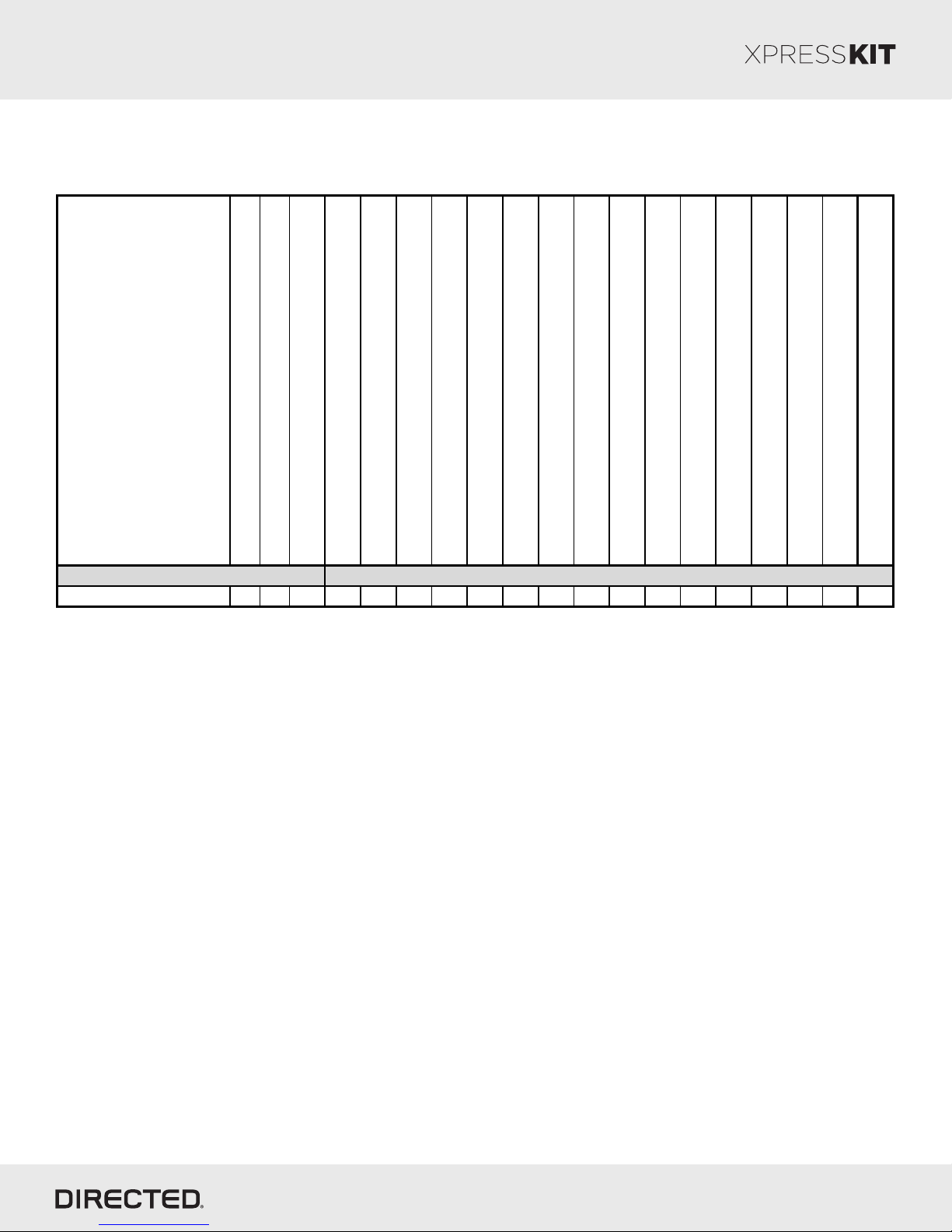
The table below lists the vehicles and features which are compatible with this product. Refer to the following pages for
more information on installation wiring, programming and troubleshooting for these vehicles.
Vehicle s
Page 2
2016
2015
2014
PK-Immobilizer Bypass-Data No Key Req'd
DL-Arm Factory Security
DL-Disarm Factory Security
DL-Door Lock Control
DL-Door Unlock
DL-Driver Priority Unlock
FOB-Control of aftermarket alarm with OEM remote
RS-SmartStart
RS-Tach / RPM Output
SS-Entry Monitoring ALL Door Pins
SS-Entry Monitoring Hood Pin
SS-Entry Monitoring Trunk/Hatch Pin
SS-Factory Alarm Trigger Monitoring
ST-Brake Status (foot brake)
ST-E-Brake Status
Mitsubishi
Outlander (Smart Key) • • • • • • • • • D D • • • • D • • •
Lege nd:
DL: OE Door Lock & Alarm Controls
FOB: Sync CAN Interf ace w / FOB Remote
PK: Transponder & Immobilizer Override
RS: Engine Start & Status
SS: Entry Point Status-Security
ST: Function/Feature Status
ST-Ignition Status
© 2017 Directed. All rights reserved.
Platform: DBALL2
Firmware: MIT2
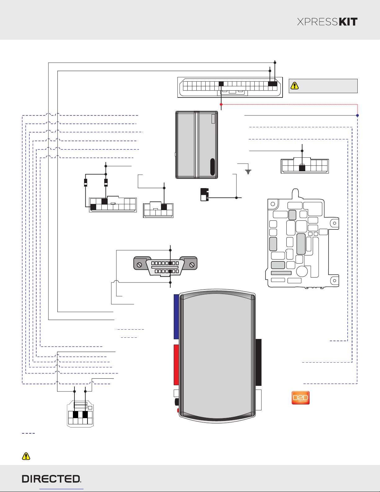
Wiring Diagram
C-417
(white conn. at
fusebox in driver dash)
HS CAN 2 Low: Red/White, pin 16
HS CAN 1 High: Yellow/Pink, pin 17
30 23 2033 26
28
[2] (-) Lock: Gray, pin 28
1932 25 223536
411 71415
Rev.: 20170620
Page 3
162917
1831 24 2134 27
18 29 512
310 613
Use only for Ignition
controlled locks feature [2].
(+) Parking
Lights (left):
White/Black,
pin 6
(+) Parking
Lights
6 Amp
(right):
diodes
Black/
White, pin 3
1
2
3
7 10
6
8 119 12 13
C-418
(white conn.at fusebox
in driver dash)
(-) Hood Status Input
(+) Brake Status Input
[1] (AC) Tach Input
(-) Trunk Status Input
(-) Door Status Input
(-) E-Brake Status Input
(+) Parking Lights Output
(+) Ignition Output
(+) Ignition:
Brown/Red,
5
4
pin 2
1
2
5 74 638
C-402
(white conn. at
fusebox in driver dash)
HS CA N High: Yellow, pin 6
1
9
HS CA N Low: Brown, pin 14
Starter
fusebox in driver dash)
8
16
Diagnostic connector
OBDII
(connector side view)
(-) Lock Output
Remote
(-) Unlock Output
(-) GWR (Status)
(+) Starter Output
(-) Ground
(+) 12V
1
(+) 12V:
White, pin 2
2
C-410
(black conn. at
(+) Starter: Violet, pin 9
5
1 2
7 10
638 11912 13
(white conn. at fusebox in driver dash)
C-402
C-420
C-418
C-417
4
C-420
C-410
Fuse Box
in driver dash
HS CA N 1 High: Tan/Black: 3
HS CA N 1 Low: Tan: 4
14 12
2
RF
Prog. Button
LED
DBALL2
10: Blue/White: (-) GWR (Status) Input
10
2: Blue: (-) Unlock Input
1: Green: (-) Lock Input
(+)12V
4
RX
(-) Ground
TX
P#: XKD2D65
(-) PTS 1:
Yellow, pin 2
3
2
1
(+) 12V (+) 12V: Red: 13
(-) E-Brake Status Output: Black/White: 1
(-) Door Status Output: Green/White: 3
(-) Trunk Status Output: Red/Black: 4
[1] (AC) Tach Output: Violet/White: 5
(-) Hood Status Output: Blue/Red: 12
(+) PTS 2:
Lt. Green/Red, pin 4
Engine Start/Stop Switch
5
4
(white conn. at PTS button)
109876
HS CA N 2 High: Orange/Green: 5
HS CA N 2 Low: Orange/Brown: 6
(-) Ground: Black: 14(-) Ground
(-) PTS 1 Output: Green/Black: 2
(+) Brake Status Output: Gray: 6
(+) PTS 2 Output: Violet/Brown: 9
Not required in D2D mode.
[1] Tach wire is an optional connection required on some remote starters, which do not support a tach signal in D2D.
[2] Connect Lock wire only if ignition controlled locks feature is active. This feature is configurable in your remote starter.
Unless specified otherwise, all connectors are displayed from the wire side, with the exception of the OBDII diagnostic connector.
© 2017 Directed. All rights reserved.
Platform: DBALL2
Firmware: MIT2
Rev.: 20170620
Page 4
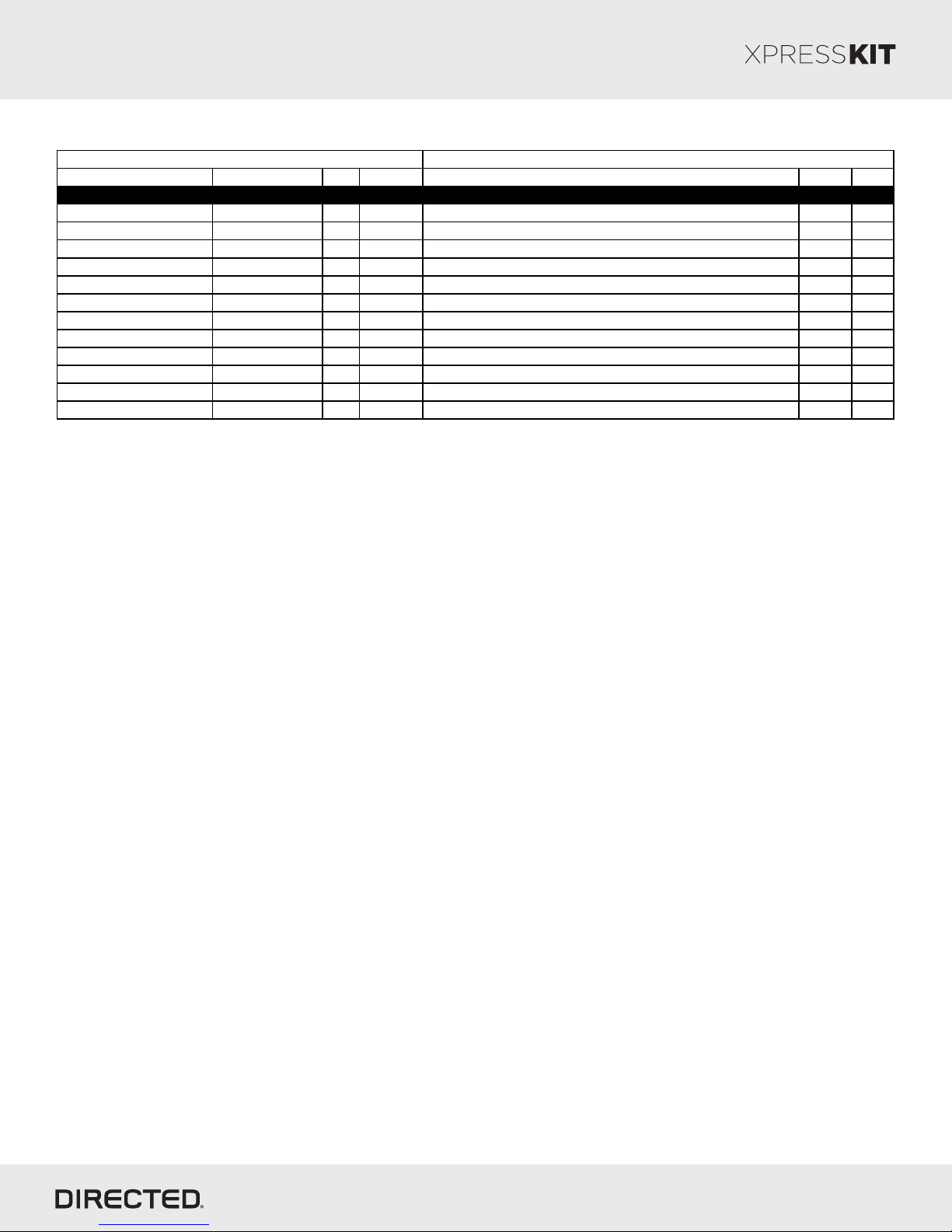
Vehicle Wiring Reference Chart
Wire Informa tion Connector Information
Function Color Pin Pola rity Location Color Pins
Mitsubishi Outla nde r (Smart Key) 2014-2015
HS CAN 1 High Yellow 6 Data OBDII diagnostic connector, under driver dash. Black 16
HS CAN 1 Low Brown 14 Data OBDII diagnostic connector, under driver dash. Black 16
HS CAN 2 High Yellow/Pink 17 Data C-417 connector, at fuse box in driver dash. White 36
HS CAN 2 Low Red/White 16 Data C-417 connector, at fuse box in driver dash. White 36
PTS 1 Yellow 2 (-) Engine Start/Stop Switch, located at Push-To-Start button. White 10
PTS 2 Lt. Green/Red 4 (+) Engine Start/Stop Switch, located at Push-To-Start button. White 10
Ignition Brown/Red 2 (+) C-402 connector, at fuse box in driver dash. White 8
12V W hite 2 (+) C-410 connector, at fuse box in driver dash. Black 2
Lock Gray 28 (-) C-417 connector, at fuse box in driver dash. White 36
Parking Lights (right) Black/White 3 (-) C-418 connector, at fuse box in driver dash. White 13
Parking Lights (left) White/Black 6 (-) C-418 connector, at fuse box in driver dash. White 13
Starter Violet 9 (+) C-420 connector, at fuse box in driver dash. White 13
© 2017 Directed. All rights reserved.
 Loading...