

Page 1

© 2013 Directed, Vista, CA—all rights reserved
N535T 2013-08
535T Window
Automation System
Installation Guide
NOTE: This product is intended for installation by a professional installer only!
Any attempt to install this product by any person other than a trained professional
may result in severe damage to a vehicle’s electrical system and components.
Page 2

© 2013
Directed. All rights reserved.
3
Contents
535T Window Automation System ..............................................................................................4
Operating Instructions ..................................................................................................................4
Dip Switch Settings ......................................................................................................................5
2 Window–Wiring Diagram .........................................................................................................7
Before installation! ........................................................................................................................7
Main Harness 1–Wire Connection Guide ....................................................................................8
Main Harness 2–Wire Connection Guide ..................................................................................10
Main Harness 3–Wire Connection Guide ..................................................................................11
2 Window Connections ..............................................................................................................12
Driver Side ..............................................................................................................................12
Passenger Side .........................................................................................................................13
Factory Control Modules (Description) ..................................................................................13
Systems with Factory Control Modules (Driver Side) .............................................................14
Systems with Factory Control Modules (Passenger Side) ........................................................14
535T Programming ....................................................................................................................15
Enter Learn Routine (2 window mode) ..................................................................................15
Exit Learn Routine ..................................................................................................................15
Vent Learn Routine ................................................................................................................16
Exit Vent Learn Routine .........................................................................................................16
4 Window Wiring Diagram ........................................................................................................17
Type A Systems (Description) .................................................................................................17
Type A Systems (Wiring) ........................................................................................................18
Type B Systems (Description ..................................................................................................19
Type B Systems (Wiring) ........................................................................................................19
Type C Systems (Description ..................................................................................................20
Type C Systems Front Windows (Wiring) ..............................................................................20
Type C Systems Rear Windows (Wiring) ...............................................................................21
Enter Learn Routine (4 window mode) ......................................................................................22
Exit Learn Routine .................................................................................................................22
Troubleshooting ..........................................................................................................................23
Page 3
4 © 2013
Directed. All rights reserved.
535T Window Automation System
The 535T window automation system controls the operation of 2 windows in both directions or
4 windows in 1 direction. The 535T automatically rolls up the power windows when the security
system is armed, as well as providing “one-touch” operation from the vehicle window switch in
either direction. The 535T can also be used to vent or roll the windows down with an auxiliary
channel from the security system.
NOTE: One-touch and vent functions do not work in 4 window mode. One-touch function is not compatible with vehicles that vent the window upon opening a door. This feature is typical on most convertibles
or coupes such as the Nissan 350Z, Ford Mustang, or BMW Z series.
Operating Instructions
To roll the windows up:
Simply arm the vehicle security system, the windows will roll up
completely.
To arm the security system and leave the windows down:
1. Press the auxiliary channel that is controlling the down function.
2. Within 5 seconds arm the security system.
3. The security system will arm, but the windows will remain down.
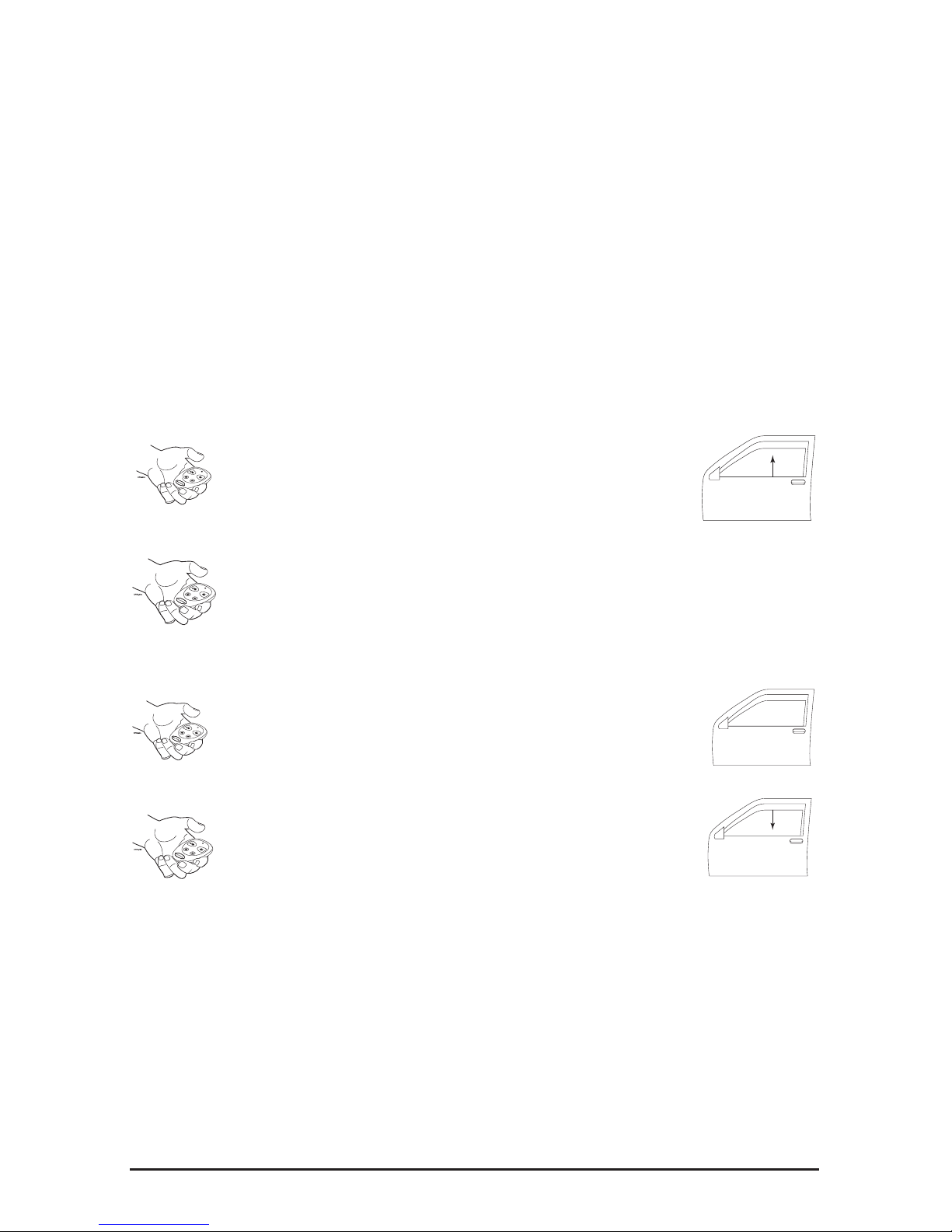
To vent the windows (not available in 4 window mode):
At any time, press and release the auxiliary channel of the security
system and the windows will vent to the programmed setting.
To roll the windows down (not available in 4 window mode):
At any time, press and hold the auxiliary channel of the security
system for 3 seconds, the windows will vent and then continue to roll
down.
NOTE: If using a delayed auxiliary channel from the security system, such as trunk release, to control
the windows down operation, the transmitter button will have to be pressed for 1.5 seconds to vent the
windows and 4.5 seconds to roll the windows all the way down.
To activate “one-touch” operation (not available in 4 window mode):
1. Turn on the ignition.
2. Simply tap the vehicle window switch in either direction, the window will roll up or down
completely.
Page 4
© 2013
Directed. All rights reserved.
5
To stop the window:
1. Turn off the ignition.
2. Tap the vehicle window switch in either direction while the window is in motion.
NOTE: If “one-touch” operation is desired from the passenger switch, the passenger side wires will need
to be run into the passenger door and interfaced between the passenger switch and the window motor.
If one touch is not desired simply turn on dip switch number 2
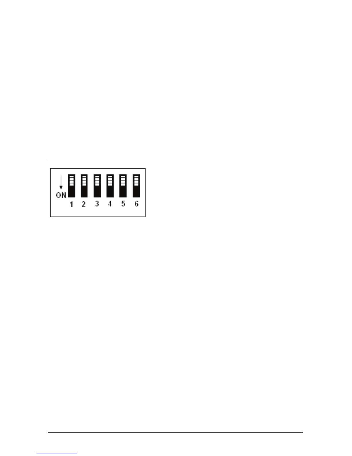
Dip Switch Settings
The 535T has several functions that can be programmed on or off by the setting of the dipswitches
on the side of the module. Listed below are the features that can be programmed by the dipswitches.
Default settings are in the OFF position.
Dipswitch 1 2 Window/4 Window Mode
Dipswitch 2 One Touch Control
Dipswitch 3 Window Switch Polarity
Dipswitch 4 Not Used
Dipswitch 5 Siren Input Polarity
Dipswitch 6 Prewarn/Full Trigger Close
DIPSWITCH 1, 2 window/4 window mode:
In the OFF position the 535T will control 2 windows in 2 directions. In the ON position the 535T
will control 4 windows in 1 direction.
DIPSWITCH 2, one touch control:
In the OFF position the 535T will give the customer “one touch” up and down operation from the
switch. In the ON position the “one touch” feature does not function.
NOTE: If “one touch” operation is desired from the passenger switch, the passenger side wires will need
to be interfaced in the passenger door. “One touch” does not function in 4 window mode. This feature
may not be compatible with vehicles that have a “vent” feature upon opening a door. Most coupes or
convertibles such as the Nissan 350Z, Ford Mustang or BMW Z series are incompatible with this feature.
DIPSWITCH 3, window switch polarity:
In the OFF position the 535T will respond to (+) positive inputs on the switch wires. For type A
and type C systems, the switch must be set to the ON position. In the off position the 535T will
respond to (-) negative inputs on the switch wires. Remember, the type B system switches it’s wires
to (-) ground rather than +12V when the switch is in use.
Page 5

6 © 2013
Directed. All rights reserved.
DIPSWITCH 4:
NOT USED.
DIPSWITCH 5, siren input polarity:
In the OFF position the 535T will close the windows when a (+) positive is received on the Brown
H3/5 wire of the 535T. In the ON position the 535T will close the windows when a (-) negative
is received on the Brown H3/5 wire of the 535T.
NOTE: The siren trigger feature will only work when the Brown H3/5 wire of the 535T is wired to an
aftermarket security system and the windows will need to be in the down position with the security system
in the armed state.
DIPSWITCH 6, pre-warn or full trigger close:
In the OFF position the 535T after a 2 second delay will roll the windows up when the security
system is in “Full Trigger” mode.
In the ON position the 535T will immediately roll the windows up when the security system is in
“Warnaway” mode.
NOTE: The brown H3/5 wire needs to be connected and the correct polarity selected (see dip switch
5 settings) for this feature to work. When dipswitch #6 is in the ON position (warn away mode) and the
535T is tied into a security/remote start system, if the windows are in the down position and the vehicle
is remote started the windows will roll up if the system is armed or disarmed during the remote start time
period. To bypass this function, you can either program off the anti-grind feature of a Directed system or
perform the silent arm/disarm command with the system.
Page 6
© 2013
Directed. All rights reserved.
7
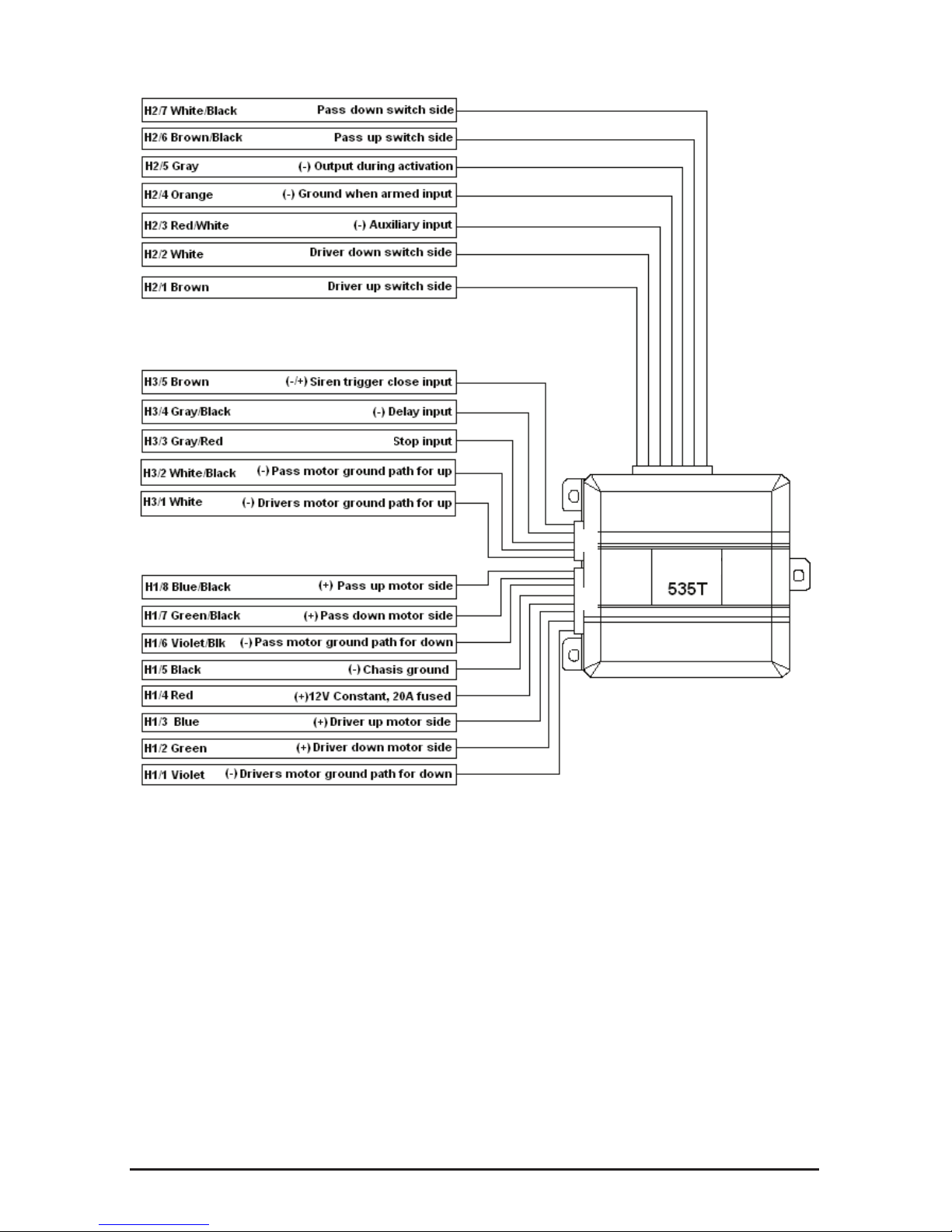
2 Window–Wiring Diagram
H2
H3
H1
(-)
NOTE: All ground wires (H3/2 white/black, H3/1 white, H1/6 violet/black, H1/5 black and H1/1
violet) must be connected for the system to function correctly.
Before installation!
Verify that all windows work correctly with their respective switches.
Locate and access the driver window motor wires and/or the master window switch.
Page 7
8 © 2013
Directed. All rights reserved.
Disconnect the driver window motor circuit and disconnect the master window switch.
Place the vehicle in the “ignition ON” state using the key or push button ignition/start system.
Turn the vehicle completely off.
Reconnect the window motor circuit and master window switch and verify that the windows still
operate.
If the windows no longer operate normally, the vehicle may require a window programming
procedure after these wires are disconnected. If this is the case, stop the installation and return the
vehicle to its initial condition.
The 535T interrupts the power window circuit in order to control the windows in either direction.
If the vehicle requires a window learn procedure after each time the window circuit is disconnected,
it is not compatible for aftermarket window control modules such as the 535T.
Most vehicles not compatible with the 535T have an OEM comfort closure feature accessible
from the driver door key cylinder. Consult the vehicle owners manual and/or Directed Technical
Support for more information if your vehicle is equipped with an OEM comfort closure feature
that may be used as an alternative to aftermarket window control modules.
NOTE: Window automation is not recommended on vehicles where the window motor is part of a door
module.
Main Harness 1–Wire Connection Guide
H1/1 VIOLET: Ground path, driver window motor down
This wire provides a ground path for the driver’s window motor down side. Connect this wire to
a good ground point in the vehicle (preferably make a ground in the kick panel that is closest to
the 535T).
Page 8

© 2013
Directed. All rights reserved.
9
H1/2 GREEN Driver window down motor side
Cut the down (driver) wire at the switch or motor and connect this wire to the motor side of the
wire.
H1/3 BLUE Driver window up motor side
Cut the up (driver) wire at the switch or motor and connect this wire to the motor side of the wire.
H1/4 RED (+) 12V constant, 20A fused
Connect this wire to a constant 12V fused source that is capable of handling a high current draw,
such as the ignition harness or battery.
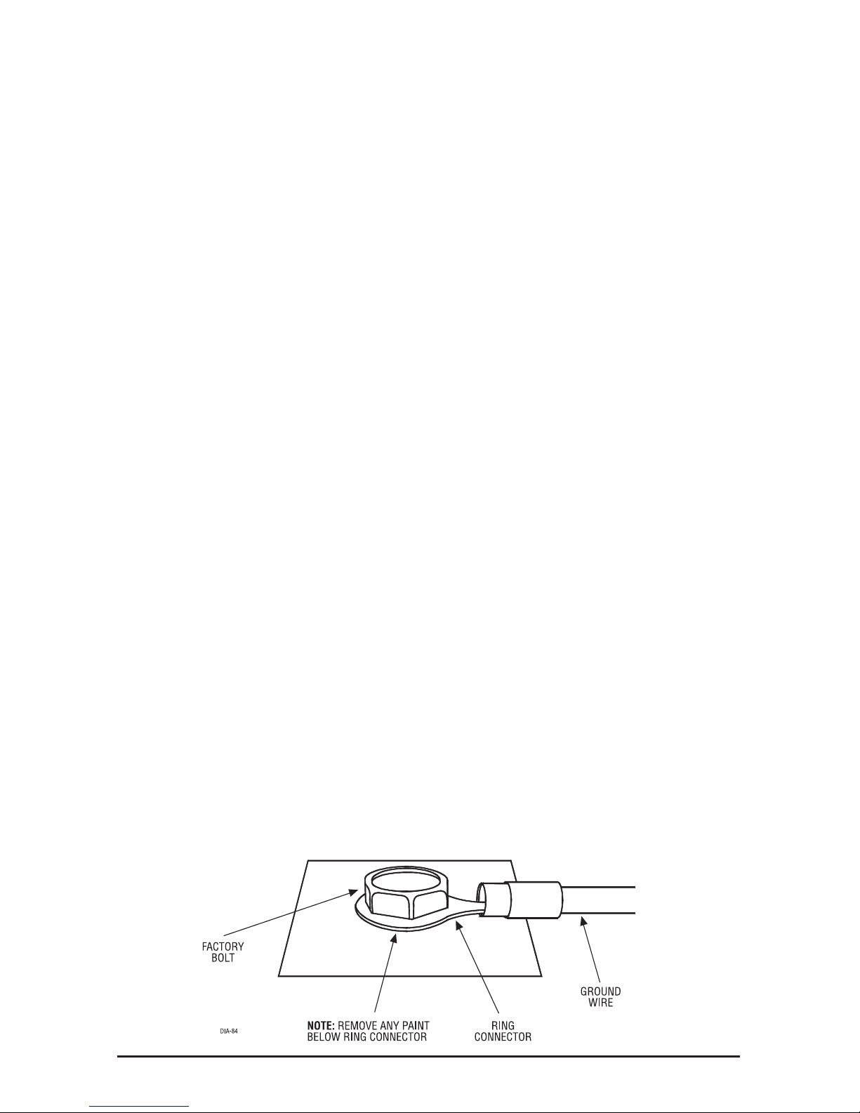
H1/5 BLACK (-) Chassis ground
Connect this wire to a good ground point in the vehicle (preferably make a ground in the kickpanel
that is closest to the 535T).
H1/6 VIOLET/BLACK Ground path, passenger window motor down
This wire provides a ground path for the passenger window motor down side. Connect this wire
to a good ground point in the vehicle (preferably make a ground in the kickpanel that is closest to
the 535T).
H1/7 GREEN/BLACK Passenger window down motor side
Cut the down (passenger) wire at the switch or motor and connect this wire to the motor side of
the wire.
H1/8 BLUE/BLACK Passenger window up motor side
Cut the up (passenger) wire at the switch or motor and connect this wire to the motor side of the
wire.
Page 9

10 © 2013
Directed. All rights reserved.
Main Harness 2–Wire Connection Guide
H2/1 BROWN: Driver window up switch side
Cut the up (driver) wire at the switch or motor and connect this wire to the switch side of the wire.
NOTE: In 4 window mode, this wire is used for programming the module.
H2/2 WHITE: Driver window down switch side
Cut the down (driver) wire at the switch or motor and connect this wire to the switch side of the
wire.
NOTE: In 4 window mode, this wire is used for programming the module.
H2/3 RED/WHITE: (-) Auxiliary input
Connect this wire to a (-) validity output channel of the security system.
H2/4 ORANGE: (-) Ground when armed
Connect this wire to the (-) ground when armed output of the security system. This wire can also
be connected to an auxiliary channel of the security system to roll the windows up.
NOTE: The window switch inputs on the 535T are not active when the Orange H2/4 wire has a ground.
With Directed remote start systems, the ground while armed wire also activates when the system is remote
started, to prevent the windows rolling up (when the windows are in the down position and the vehicle is
remote started), program off the anti-grind feature on the Directed system.
H2/5 GRAY: (-) 500 mA Output during activation
Connect this wire to an optional relay to bypass sensors which may trigger the security system
during operation of the 535T or connect to the Gray/Black (-) delay of a secondary 535T to have
the windows stagger when closing. This wire continues to output (-) ground for 5 seconds after the
window motors have stopped.
H2/6 BROWN/BLACK: Passenger window up switch side
Cut the up (passenger) wire at the switch or motor and connect this wire to the switch side of the
wire.
H2/7 WHITE/BLACK: Passenger window down switch side
Cut the down (passenger) wire at the switch or motor and connect this wire to the switch side of
the wire.
Page 10

© 2013
Directed. All rights reserved.
11
Main Harness 3–Wire Connection Guide
H3/1 WHITE: Ground path, driver window motor up
This wire provides a ground path for the driver motor up side. Connect this wire to a good ground
point in the vehicle (preferably make a ground in the kickpanel that is closest to the 535T).
H3/2 WHITE/BLACK: Ground path, passenger window motor up
This wire provides a ground path for the passenger motor up side. Connect this wire to a good
ground point in the vehicle (preferably make a ground in the kickpanel that is closest to the 535T).
H3/3 GRAY/RED: (-) Stop input
The 535T will cease movement when this wire receives a negative pulse and will not continue
movement when the pulse has gone away. Connect this wire to an optional switch or an auxiliary
output from the security system.
NOTE: Can be used in conjunction with a sunroof limit switch or with an auxiliary out from the host system,
this is an optional connection and is not mandatory..
H3/4 GRAY/BLACK: (-) Delay input
This wire will prevent the 535T from moving the windows as long as it is receiving a ground.
Once the ground is removed, the 535T will begin to move the windows. This can be used with
a secondary 535T to make the windows stagger when arming the security system. For example:
When arming the security system, the front windows will roll up first and 5 seconds after the front
windows are fully closed, the rear windows will start to roll up, or vice versa. The vent and siren
roll up features are also affected by this input. If you have more than one 535T and this wire is
connected, when you vent the windows, 1 set of windows will vent first and then the 2nd set of
windows will vent and if the alarm is triggered with the windows rolled down, the windows will still
be staggered when rolling up from the alarm trigger. This input wire can also be used to delay the
window roll up when the anti-grind feature on a directed system is enabled and the windows roll
up when remote starting. Connecting this wire to the (-) starter output will pause the window roll
up during the crank sequence during remote start and will prevent maximum current draw during
this sequence (see the following diagram for connection details)..
NOTE: This wire is an option and it is not mandatory to connect.
Page 11

12 © 2013
Directed. All rights reserved.
H3/5 BROWN: (-/+) Siren trigger close input
This wire will roll up the windows when it receives a negative or positive (programmable via dip
switch 5) from the security system’s siren output (programmable via dip switch 6 for warnaway
or full trigger) when the security system has been armed with the windows in the down position.
Connect this wire to the siren output of the security system.
NOTE: This wire is an option and it is not mandatory to connect.
2 Window Connections
Driver Side
Page 12

© 2013
Directed. All rights reserved.
13
Passenger Side
(-) Chassis
Ground
(+) 12V
Ignition
Factory Control Modules (Description)
Some windows use either a central control module, or control modules in each door. These systems
are less common than direct wired systems. These can be found in many newer Volkswagens,
BMWs, Isuzus, Maximas, Grand Cherokees, and many Ford vehicles. If the vehicle has one of
these systems, the 535T must be interfaced between the window switch and the window motor,
effectively eliminating the factory window control module. This often requires the wires to be run
into each door. The 535T monitors the AC “noise” generated by the motion of the motor. For this
reason the 535T cannot drive relays or control modules in the system.
Page 13

14 © 2013
Directed. All rights reserved.
Systems with Factory Control Modules (Driver Side)
Systems with Factory Control Modules (Passenger Side)
Page 14

© 2013
Directed. All rights reserved.
15
535T Programming
When installation is complete the 535T will need to be programmed to learn the window threshold
of the vehicle.
To program the 535T make sure that dipswitch 1 is in the OFF (2 window) position.
Enter Learn Routine (2 window mode)
1. With the vehicle’s ignition on, temporarily connect the Aux channel input (H2/3 Red/White)
wire to ground. This wire must remain grounded during the entire learn procedure.
2. While the H2/3 Red/White is receiving a ground input, attempt to roll the driver window up
from the master window switch. The window should not roll up. If you have wired the 535T
so that one-touch functionality can operate from each door, this step must be performed at
that door (if installed for rear window control).
3. Continue holding the driver side window “up” switch until the window starts to close, this
should take two to three seconds. If the window does not begin to move, verify that the H2/1
Brown input is receiving (+) or (-) when you press the switch and that the polarity dip switch
is set to the appropriate position.
4. The windows now begin to close and then open a few times one by one while the 535T
attempts to learn the “fully opened” and “fully closed” positions.
5. Once the learn procedure has completed both windows close and then vent to indicate a
successful learn routine.
Exit Learn Routine
The learn routine is immediately canceled and stops window travel under any of the following
conditions:
• H2/3 Red/White ground ceases
• Any window switch is pressed after learn routing has begun
• If the window learn procedure detects a window failure or is unable to detect the “fully
opened” or “fully closed” positions.
Page 15

16 © 2013
Directed. All rights reserved.
Vent Learn Routine
The Learn Routine must be completed before Vent Learn Routine can be performed.
1. Roll both windows up all the way by holding both switches.
NOTE: The 535T needs to see BOTH switch inputs at the same time to enter programming.
2. Once the windows are all the way up; press and release the driver UP switch six times.
3. Press and hold the driver window DOWN switch until the window reaches the desired vent
position, and then release the switch. Use caution not to activate any OEM “AUTO” down
feature during this step!
4. The 535T records the time the output was active and sets it to memory as the vent time.
5. Two seconds after the vent time is set to memory the 535T rolls up the driver window and
then vents both windows using the learned vent time indicating that the learn routine was
successful.
Exit Vent Learn Routine
Either of the learn routines are exited if any of the following occurs:
• There is no activity on the inputs for more than 15 seconds.
• Incorrect switch input order.
• Any switch input is seen during the learn routine.
• Current threshold exceeds the units capabilities.
• Power loss.
Page 16

© 2013
Directed. All rights reserved.
17
4 Window Wiring Diagram
H3/3 Gray/Red (-) Stop input
H3/4 Gray/Black (-) Delay input
H3/5 Brown (-/+) Siren trigger up input
H3/2 White/Black Pass rear window up switch side
H3/1 White Pass front window up switch side
H2/5 Gray (-) Ground while active 500mA current output
H2/1 Brown Driver Up Switch
H2/7 White/Black Not Used
H2/6 Brown/Black Not Used
H2/3 Red/White (-) Auxiliary Input
H2/4 Orange (-) Ground when armed input
H2/2 White Driver Down Switch
H2
H3
H1
Type A Systems (Description)
The window switch outputs rest at ground. When the switch is not being used, both wires will
show ground when tested. One wire is connected to (+) 12V when the switch is in the up position,
and the other is connected to (+) 12V when the switch is in the down position. This is the most
common type for Domestic and Asian vehicles.
Page 17

18 © 2013
Directed. All rights reserved.
Type A Systems (Wiring)
Pass
Pass
Driver
Driver
Brown H2/1
White
H2/2
Page 18

© 2013
Directed. All rights reserved.
19
Type B Systems (Description
This system will have a switched wire that goes to (-) ground as the switch is operated, and another
wire which will remain at (+) 12V with ignition. The wire you want to cut and interrupt is the
wire that does not change state, but remains at (+) 12V ignition when the switch is operated in the
desired direction. Remember that using the relay as shown in the diagram effectively changes the
Type B circuit to a Type A circuit only during module activation.
Type B Systems (Wiring)
Brown H2/1
White
H2/2
Page 19

20 © 2013
Directed. All rights reserved.
Type C Systems (Description
Switch outputs rest open, and both (+) 12V and (-) ground are switched for each direction of
operation. This type of circuit requires 2 relays for each set of windows to supply ground to each
motor circuit. The type is rare, but is found in Chevrolet Camaro/Pontiac Firebird and also newer
GM pickups and SUVs.
Type C Systems Front Windows (Wiring)
Brown H2/1
White
H2/2
Page 20

© 2013
Directed. All rights reserved.
21
Type C Systems Rear Windows (Wiring)
Page 21

22 © 2013
Directed. All rights reserved.
Enter Learn Routine (4 window mode)
1. Roll the windows down.
2. With the vehicle’s ignition on, temporarily connect the Aux channel input (H2/3 Red/White)
wire to ground. This wire must remain grounded during the entire learn procedure.
3. While the H2/3 Red/White is receiving a ground input, attempt to roll the driver window up
from the master window switch.
4. Continue holding the driver side window “up” for about two to three seconds and then release
the switch. If the window does not continue to move after you have released the switch, verify that
the H2/1 Brown input is receiving (+) or (-) when you press the switch and that the polarity dip
switch is set to the appropriate position.
5. The windows now begin to close one by one while the 535T attempts to learn the “fully closed”
positions for each window.
6. Once all of the windows have been closed by the 535T, the learn procedure has completed.
Exit Learn Routine
The learn routine is immediately canceled and stops window travel under any of the following
conditions:
• H2/3 Red/White ground ceases
• Any window switch is pressed after learn routing has begun
• If the window learn procedure detects a window failure or is unable to detect the “fully
closed” positions.
Page 22

© 2013
Directed. All rights reserved.
23
Troubleshooting
The 535T will not go into programming mode.
Verify that the window switch input wires are connected correctly. It may be necessary to verify that
the window switch input wire is receiving (+) or (-) when you activate the corresponding window
switch. Also, make sure the vehicle’s key is in the ON position. If the vehicle is equipped with a
push button ignition/start system, place the car into an ignition mode that allows the windows to
operate normally.
The windows do not move, and the 535T’s fuse blows.
The switch side and the motor side connections may be reversed. Always make these determinations
while using the master switch (if there is one), and cut both wires before testing if any uncertainty exists.
The window moves an inch or so, and stops.
Does the vehicle have a one-touch module? if so, make sure that the switch wires are connected at
the window switch and the motor wires are connected at the window motor.
Is the window too efficient or inefficient? If you help the window up does it move the entire
direction? If so, you may need to reprogram the 535T.
One window works fine, but the other does not move.
Does the window in question have a one-touch module? if so, make sure that the switch wires are
connected at the window switch and the motor wires are connected at the window motor.
I can’t find any wires on the switch that seem to work.
Some newer vehicles use unusual window control modules. Many of these require the 535T wires
to be run into each door. If you are unsure, call Directed Tech Support for details.
My siren triggers while the 535T is rolling up/down the windows.
Be sure to place the 535T far away from any impact sensor to keep from triggering the security
system. If this does not help refer to the following diagram to prevent the security from false
triggering when the 535T is controlling the windows.
Page 23

24 © 2013
Directed. All rights reserved.
 Loading...