

Page 1
Electronics Europe GmbH & Co.KG
TTeecchh..--SSuuppppoorrtt
01900-33420
25ct/min.
((DDiirreecctteedd))
TTeecchh..--SSuuppppoorrtt
01900-33410
25ct/min.
((CClliiffffoorrdd))
AAnnsscchhrriifftt
Langwadener Strasse 60
D-41516 Grevenbroich
IInntteerrnneett
www.directed.de
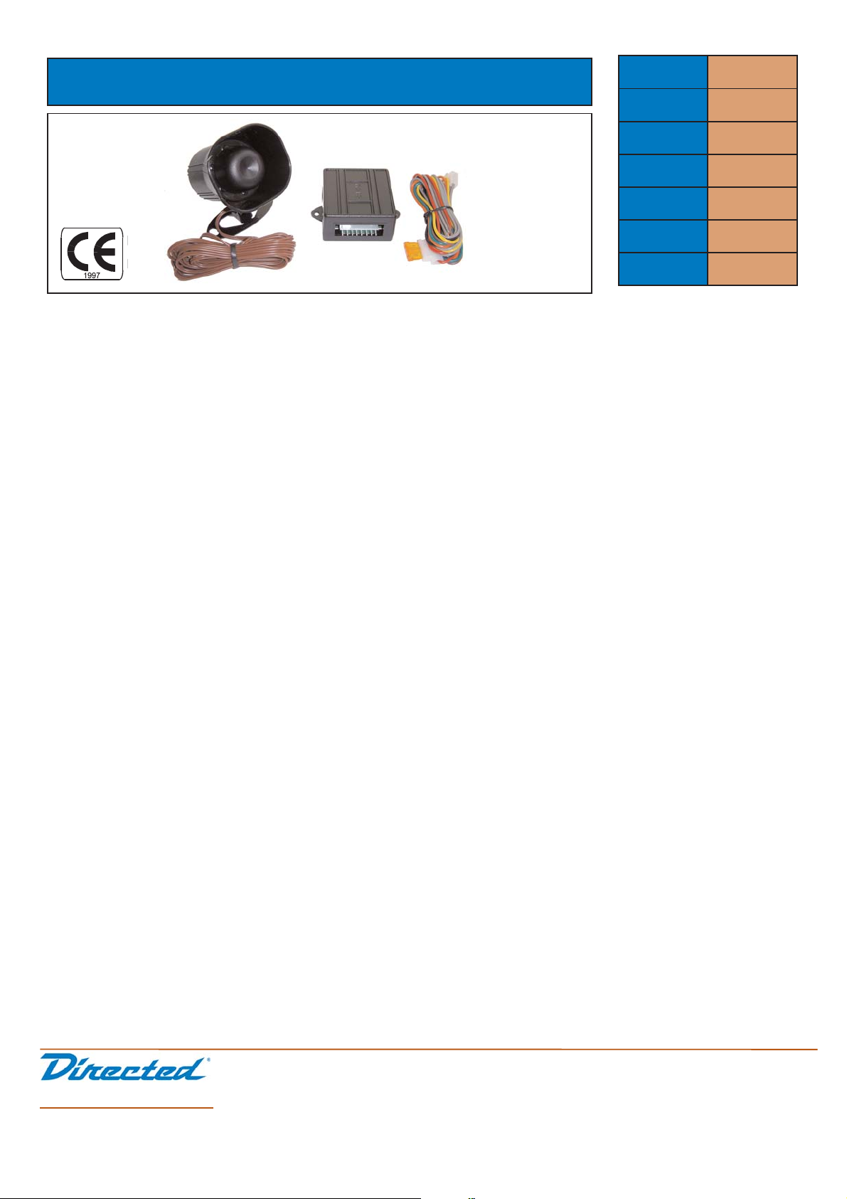
SPRACHMODUL 516U
Montage- und Bedienungsanleitung
Diese Informationen werden von Directed Electronics ihren Vertragspartnern kostenlos zur
Verfügung gestellt. Sie dienen ausschließlich als Orientierung bei der Installation von
Sicherheitssystemen der Handelsmarken, die von Directed Electronics vertrieben werden. Eine
Weitergabe an Dritte ist grundsätzlich untersagt. Es wird keine Haftung für die Richtigkeit der
Daten bzw. eventuelle Schäden übernommen. Alle Anschlüsse müssen vor der Installation
geprüft werden.
Hersteller DEI
Artikel Nr. 516U
Bestell Nr.
Bauform Aufbau
Spannung 12 Volt
Seite 1 / 2
Stand 09/2004
©
2004 Directed Electronics Europe GmbH & Co. KG
SUPPORT
SUPPORT
ACHTUNG: Das 516U Sprachmodul kann an jedes Alarmsystem angeschlossen werden, das mit12V (+) betrieben
wird und entweder einen Ausgang hat, der nach dem SCHÄRFEN Masse (-) gibt, oder eine Sirene hat die mit positiv 12Volt angesteuert wird. Das Sprachmodul beinhaltet die Elektronik selbst und einen Lautsprecher zur
Sprachausgabe.
BEFESTIGUNG DES SPRACHMODULS
Suchen Sie im Fahrzeug (Vielleicht unter dem Armaturenbrett oder hinter dem Handschuhfach), vorzugsweise in der
Nähe der Alarmanlage, einen Platz für das Sprachmodul. Befestigen Sie das Sprachmodul nicht sofort sondern
warten Sie, bis Sie alle Anschlüsse durchgeführt haben und die Funktion des Moduls überprüft haben. Denken Sie
bitte auch daran, das Sprachmodul leiser zu drehen.
VERKABELUNG
GRAU (~) LAUTSPRECHER AUSGÄNGE:
ACHTUNG: Lautsprecherkabel dürfen niemals mit Masse (-) in Verbindung kommen. Diese Kabel haben keine
Polarität und können daher beliebig mit dem Druckkammerlautsprecher des 516U verbunden werden. Der
Lautsprecher sollte im Motorraum angebracht werden. Verbinden Sie die Lautsprecherkabel unter dem
Armaturenbrett mit den GRAUEN Kabeln des Sprachmoduls. Der Lautsprecher selbst sollte von Aussen nicht erreichbar sein. Montieren Sie den Lautsprecher nicht in unmittelbarer Nähe von Hitzequellen (Auspuff).
SCHWARZ (-) MASSE
Verbinden Sie dieses Kabel mit der Karosserie des Fahrzeuges oder mit einem bereits bestehenden Massepunkt
im Fahrzeug. Es ist empfehlenswert, den selben Massepunkt zu wählen, mit welchem man das Alarmsystem verbunden hat.
ROT (+12V) DAUERPLUS
Bevor Sie dieses Kabel anschliessen, stellen Sie bitte sicher, dass die Sicherung am ROTEN Draht entfernt wurde.
Dieses Kabel muss mit einer 12V(+) Spannungsquelle verbunden werden. Über dieses Kabel muss das
Sprachmodul dauernd 12V(+) erhalten.
ORANGE (-) MASSE WENN SCHARF EINGANG
Verbinden Sie das ORANGE Kabel mit dem Kabel der Alarmanlage, dass sobald Sie SCHARF geschaltet haben,
MASSE (-) gibt und diese Masse wieder abfällt, sobald Sie UNSCHARF schalten. Dieses Kabel generiert im
Sprachmodul die SCHARF und UNSCHARF Meldung über die ankommende und abfallende MASSE.
ACHTUNG: Wenn über das ORANGE Kabel der DEI Alarmanlage auch ein STARTER KILL Relais gesteuert wird,
setzen Sie bitte eine 1N4004 (1A) Sperrdiode zur Trennung.
Page 2
SUPPORT
Electronics Europe GmbH & Co.KG
TTeecchh..--SSuuppppoorrtt
01900-33420
25ct/min.
((DDiirreecctteedd))
TTeecchh..--SSuuppppoorrtt
01900-33410
25ct/min.
((CClliiffffoorrdd))
AAnnsscchhrriifftt
Langwadener Strasse 60
D-41516 Grevenbroich
IInntteerrnneett
www.directed.de
GELB (+12V) ZÜNDUNGSPLUS EINGANG
Dieser Eingang verhindert, dass das Sprachmodul aktiviert wird und eine Meldung abgibt, wenn die Zündung eingeschaltet ist. Verbinden Sie diesen Draht mit einem Draht vom Zündschloss, der 12V (+) permanet führt.
(Das Kabel muss während des Startvorgangs weiterhin Strom führen)
Das richtige Kabel gibt Masse solange die Zündung nicht eingeschaltet ist.
BRAUN (+12V) SIRENEN-EINGANG
Verbinden Sie das braune Kabel mit dem braunen Kabel der DEI Alarmanlage.
(Wenn Sie das 516U mit einem anderen Fabrikat verwenden kann es zu doppelten Sprachmeldungen kommen.)
GRÜN (-) WARNSTUFE-EINGANG
Verbinden Sie dieses Kabel mit dem negativen Ausgang ihres Sensor der die Vorwarnstufe aktivieren soll.
PROGRAMMIERUNG
Mit Hilfe der vier Schalter wird das Sprachmodul 516U konfiguriert. Das Modul kann entweder in englischer oder
spanischer Sprache arbeiten. Ausserdem kann man entweder die Meldung "VIPER" oder "SYSTEM" konfigurieren.
SCHALTER 1 SCHALTER 2 SPRACHMELDUNG
OFF OFF englische Viperversion
ON OFF spanische Viperversion
OFF ON spanische Standardversion
ON ON englische Standardversion
SCHALTER 3
Einschalter für "Sirenenchirp" Detector
Mit dem Schalter 3 kann man den Steuereingang des 516U konfigurieren. Ist der Schalter 3 in der "ON"-Position
so wird das 516U vom braunen Sirenenkabel und vom orangen Kabel (Masse wenn scharf) gesteuert. Steht der
Schalter 3 in der "OFF"-Position ignoriert das 516U das braune Sirenenkabel und es wird nur vom orangen Kabel
(Masse wenn scharf) Eingang gesteuert.
SCHALTER 4
Umschalter für "alle Sprachmeldungen" oder "nur Vorwarnung"
Der Schalter 4 konfiguriert welche Sprachmeldungen das 516U generiert. Befindet sich der Schalter 4 in der "ON"Position so werden alle Meldungen generiert. Befindet sich der Schalter 4 in der "OFF"-Position so wird lediglich die
"WARN-AWAY" Vorwarnstufe generiert.
Diese Informationen werden von Directed Electronics ihren Vertragspartnern kostenlos zur
Verfügung gestellt. Sie dienen ausschließlich als Orientierung bei der Installation von
Sicherheitssystemen der Handelsmarken, die von Directed Electronics vertrieben werden. Eine
Weitergabe an Dritte ist grundsätzlich untersagt. Es wird keine Haftung für die Richtigkeit der
Daten bzw. eventuelle Schäden übernommen. Alle Anschlüsse müssen vor der Installation
geprüft werden.
©
2004 Directed Electronics Europe GmbH & Co. KG
SUPPORT
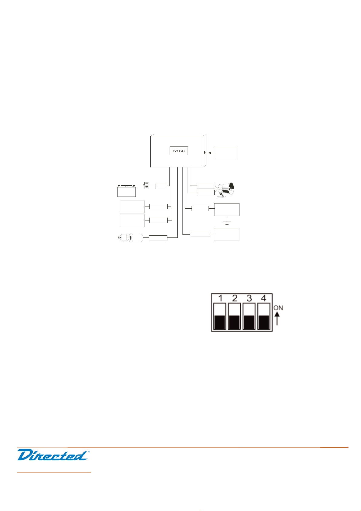
ROT
GELB
BRAUN
GRÜN
GRAU
GRAU
SCHWARZ
ORANGE*
Lautstärkeregler
BATTERIE
Sicherung
(-) Masse
Anschluß an die
Karosserie
(-) Masse wenn
scharf Eingang
Fahrzeug K15Zündungsplus
(+) Sirenen Eingang
Warnstufe
Eingang (-)
Page 3

516U Universal Voice Module
The 516U is designed to add voice response to security systems
that have a ground-when-armed output. The 516U is a universal
voice add-on. It can be programmed to generate voices in English
or Spanish as well as generic or Viper®-specific messages. The
516U can also read the siren output of most Directed systems and
will follow the Silent Mode protocol. If desired, the unit can be
used to generate the WarnAway®message only.
■ Voice Module
■ Speaker
■ Main Harness
what is included
about this unit
© 2002 Directed Electronics, Inc.
N516U 12-02
wiring diagram
■ BROWN (+) siren input: If using a Directed system, connect
this wire to the BROWN siren output of the security system.
■ GREEN (-) WarnAway
®
trigger input: Connect this wire to
the first stage output of Directed dual-stage sensors.
■ YELLOW (+) ignition input: Connect to a wire that shows
voltage when the key is in the run and crank positions.
Connect into the ignition input wire of the security system if
more convenient.
■ ORANGE (-) armed input: Connect to the ground-when-armed
output of the security system.
■ BLACK (-) chassis ground input: Connect to a paint-free
part of the vehicle’s chassis. When possible, use a factory
bolt that is not being used as a ground for any vehicle acces-
sories.
■ RED (+) 12V constant power input: Before connecting this
wire, be sure to remove the 5 amp fuse. Connect to the posi-
tive battery terminal or another constant power source.
NOTE: Always insert a fuse within 12 inches of where you
obtain power.
■ GRAY (2) speaker outputs: Connect these wires to the
speaker provided with the system. Polarity does not matter. If
these wires short to ground, the 516U will be damaged.
NOTE: When adding more than one accessory to the
average ground when armed output, the two accessories
must be diode isolated.
wire connection guide
Page 4

2
© 2002 Directed Electronics, Inc.
N516U 12-02
The 516U has selectable dipswitch settings for programming the
system’s features. The four dipswitches are located on the side of
the unit. To select a system feature setting, simply move the dip-
switch in the direction of the arrow for the ON setting, or in the
opposite direction for the OFF setting:
Dipswitches 1 and 2: Dipswitches 1 and 2 are used to program
the 516U for the desired language. They also select the “Viper” or
generic messages.
Dipswitch 3: Dipswitch 3 is used to program the 516U to read the
H1/1 BROWN siren input. In the ON setting, the 516U will monitor
the H1/1 BROWN siren input as well as the H1/4 ORANGE armed
input. In the OFF setting, the 516U will ignore the H1/1 BROWN
siren input and will only monitor the H1/4 ORANGE armed input.
Dipswitch 4: Dipswitch 4 programs which messages the 516U will
generate. In the ON position, all messages are generated. In the
OFF position, only the Warn Away message will be generated.
The 516U is a universal module that can be used in many ways.
Some of the most common applications are described below. Each
of the applications involve connecting certain inputs of the 516U,
as well as programming the module using Switches 3 and 4. In all
cases it is assumed that the voice language and type have already
been programmed.
Directed Security System
With External Shock Sensor
This interface will take advantage of all the 516U features. During
normal operation, the security system will still generate all the
standard chirp confirmation for arm and disarm. The chirp(s) will
be followed by the armed/disarmed message. If Silent Mode is
used, since the chirp is disabled, no armed/disarmed message is
generated. When the system has been triggered, four chirps are
generated on disarm and the 516U will generate a violation
message. If the GREEN WarnAway
®
input is connected, the
WarnAway
®
message will be generated whenever the system is
armed and an input is detected on the (-) WarnAway
®
input wire.
The WarnAway
®
message can be generated without any connec-
tions to the GREEN wire if the system features WarnAway
®
. the
516U will detect the WarnAway
®
chirps on the BROWN wire and
generate the WarnAway
®
message immediately after the chirps.
Connect the ORANGE wire of the 516U to the ORANGE ground-
when-armed output of the DIRECTED security system. Connect the
BROWN siren input of the 516U to the BROWN siren output of the
security system. Connect the first stage output of the shock
sensor to the GREEN input of 516U if desired. This connection is
not required, but if used, the 516U will generate the WarnAway
®
message instantly instead of after counting the WarnAway ®chirps.
Switch 3 must be on to enable the 516U to detect siren chirps
except for WarnAway
®
.
Directed Security System
With On-Board Shock Sensor
The 516U will use chirp counting to generate the armed/dis-
armed/WarnAway® messages. Since the shock sensor is on-board
the security system, it is impossible to physically connect to it.
Unless the siren chirps are completely disabled inside the 514T
siren itself, all chirps that the security system generates will be
heard. Immediately following the chirp(s), the 516U will generate
the corresponding voice message.
operation
DIPSWITCH 1 DIPSWITCH 2 MESSAGE
Off Off English Viper
On Off Spanish Viper
Off On SP System
On On ENG System
internal programming
Page 5

© 2002 Directed Electronics, Inc. Vista, CA
N516U 12-02
3
Connect the ORANGE wire of the 516U to the ORANGE ground-
when-armed output of the Directed security system. Connect the
BROWN siren input of the 516U to the BROWN siren output of the
security system.
NOTE: Switch 3 must be ON to enable the 516U to detect
siren chirps except for WarnAway
®
.
Non-Directed Security System
(no chirp detection)
The 516U will determine the state of the security system based on
the (-) armed input. It will generate the armed/disarmed message
whenever the security system is armed or disarmed. The
WarnAway
®
message will be generated whenever the system is
armed and an input is detected on the WarnAway
®
input wire.
Connect the ORANGE wire of the 516U to the ORANGE, ground-
when-armed output of the security system (consult installation
manual of the system being installed in non-Directed brand for
ground-when-armed wire color). Do not connect the BROWN wire
of the 516U. Switch 3 must be OFF to disable chirp detection.
Connect the GREEN (-) WarnAway
®
input to the output of the
sensor that will be used to trigger the WarnAway
®
message.
WarnAway®Message Only
In any of the applications above, it is possible to program the
516U to generate only the WarnAway
®
message. Switch 4 is used
to program this. If Switch 4 is ON, all messages will be generated.
If Switch 4 is OFF, only the WarnAway
®
message is generated.
Accessory A
ALARM
MODULE
Accessory B
ORANGE Ground When
Armed
 Loading...