

Directed 3901V, 3902V, 3903V Installation Manual

Model
3901V/3902V/3903V
Installation Guide
NOTE: This product is intended for installation by a profes-
sional installer only! Any attempt to install this product by any
person other than a trained professional may result in severe
damage to a vehicle’s electrical system and components.
© 2007 Directed Electronics, Vista, CA
N3901V 2007-09
Bitwriter®, Code Hopping™, Doubleguard®, ESP™, FailSafe®, Ghost
Switch™, Learn Routine™, Nite-Lite®, Nuisance Prevention® Circuitry,
Revenger®, Silent Mode™, Soft Chirp®, Stinger®, Valet®, Vehicle
Recovery System®, VRS®, and Warn Away® are all Trademarks or
Registered Trademarks of Directed Electronics.
The Bitwriter® (p/n 998T)
requires chip version 2.5 or
newer to program this unit.

Table of contents
What is included.............................................5
Control module diagram....................................5
Installation points to remember........................6
Before beginning the installation......................6
After the installation.......................................7
Tools required.................................................7
Deciding on component locations...................8
Control module...............................................8
Integrated LED/Valet® switch............................9
Starter kill relay..............................................9
Connecting your wires..................................10
Obtaining constant 12V..................................10
Finding a light wire........................................11
Main harness wire connection guide..............12
CAN harness................................................15
CAN harness wiring guide................................15
Plug-in harness...........................................16
Integrated LED/Valet®...................................16
Data port - Bitwriter®....................................16
Data port - Bootloader...................................16
Four-pin optional sensor harness......................17
On-board dual stage shock sensor..................18
Zones..........................................................18
Longterm event history...................................19
Rapid resume logic.........................................19
Multi-level secuity arming............................20
Feature programming...................................21
To access feature programming........................21
Feature menus..........................................22-23
Bitwriter® features.........................................23
Features description...............................24-26
Special features.............................................28
Vehicle Appplication Charts.....................29-33
Wiring quick reference guide..................34

5
What Is Included
■ The control module
■ 9-pin main harness
■ 4-pin sensor harness
■ LED/VALET switch
■ 3-pin CAN(control area network) harness
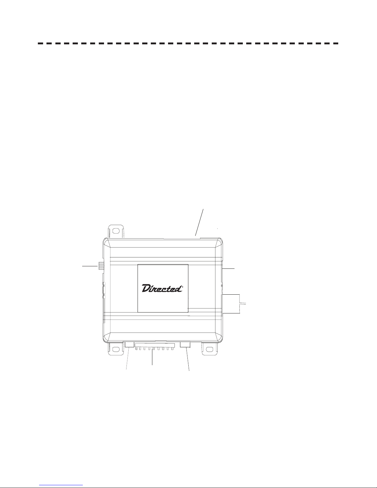
Control Module
SHOCK SENSOR
ADJUSTMENT
9-PIN
MAIN
HARNESS
DAT A PORT
BITWRITER®
(ESP2)
CAN HARNESS
DAT A PORT
BOOT LOADER
OPTIONAL SENSOR
INPUT
LED/VALET® SWITCH

© 2007 Directed Electronics—all rights reserved
6
IMPORTANT! Before you begin the install process ensure the hardware
matches the vehicle and verify the wires needed.
Installation points to remember
This product represents many years of research and development. It is very sophisticated and should be
installed by experienced security installers only. Please do not attempt installation of this product without
reading this guide.
This product is not intended for consumer installation and will have NO WARRANTY unless it is installed
by an authorized dealer. Do not disconnect the battery if the vehicle has an anti-theft coded radio. If
equipped with an airbag, avoid disconnecting the battery if possible.
IMPORTANT! Please read this entire installation guide before beginning the
installation. The installation of this security system requires interfacing with
many of the vehicle’s systems. Many new vehicles use low-voltage or multiplexed systems which can be damaged by low resistance testing devices,
such as test lights or logic probes. Test all circuits with a high-quality digital
multi-meter before making the connections.
IMPORTANT! Many airbag systems will display a diagnostic code through
Their warning light after they lose power. Disconnecting the battery requires
this code to be erased, a procedure that can require a trip to the dealer.
Before beginning the installation
■ Check with the customer to determine the LED and Valet switch locations.
■ Roll down a window to avoid being locked out of the car.
WARNING: Before beginning your install go to www.XPRESSVIP.com and be sure to print the
LATEST corresponding installation manual for the firmware that is flashed to the platform
you are using.

© 2007 Directed Electronics—all rights reserved
7
After the installation
■ Test all functions. The “Using Your System” section of the Owner's Guide is very helpful when testing.
■ When testing, don’t forget that this system is equipped with Nuisance Prevention® Circuitry (NPC). NPC
can bypass both sensor zones, making them appear to stop working.
■ Carefully reassemble the under-dash trim panels.
■ Inspect the engine compartment for tools that may have been left behind.
Tools required
This is a general list of tools required to complete the installation of this security system for most vehicles.
Some vehicles may require additinal tools.
■ Digital multi-meter
■ Nutdriver and/or socket set
■ Wire cutters/strippers
■ Panel removal tool
■ Solderless terminal crimpers
■ Drill bit set
■ Cordless power drill
■ Phillips head screwdriver
■ Torx driver set - Work light
8
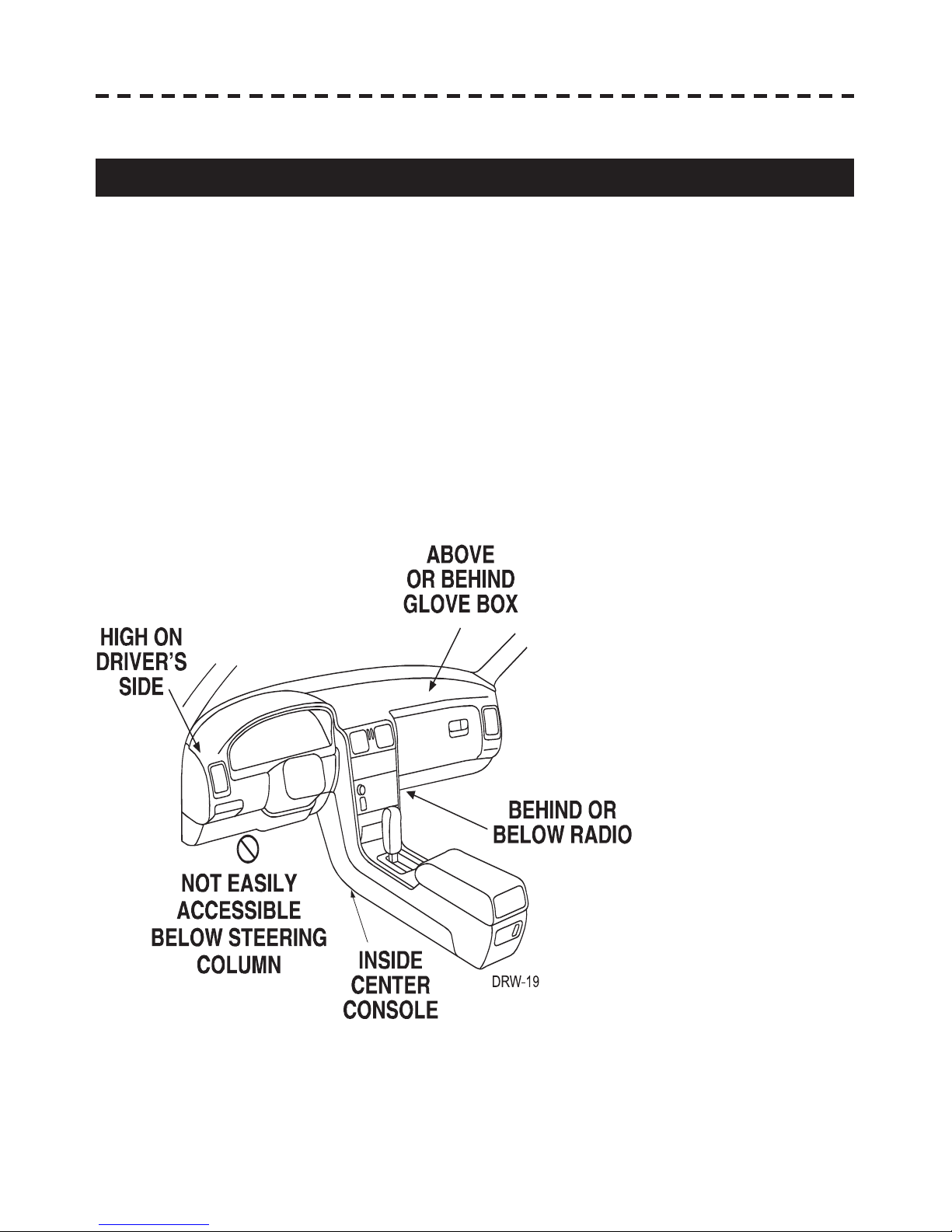
Deciding on component locations
Control module
Some things to remember about where to mount the control module
■ Never put the control module in the engine compartment!
■ The first step in wiring a vehicle is removing the driver's side under-dash panel to access the starter
and ignition wires. If the control module is placed just behind the driver's side dash it can easily be
disconnected.
■ When mounting the control module, try to find a secure location that will not require you to extend the
harnesses’ wires (they are 1.5 meters long). Keep it away from the heater core (or any other heat sources)
and any obvious leaks.
■ Some good control module locations are: Above the glove box, inside the center console, above the
under-dash fuse box, or above the radio.

© 2007 Directed Electronics—all rights reserved
9
Integrated LED/Valet switch
Things to remember when po si tion ing the integrated LED/Valet switch:
■ It should be visible from both sides and the rear of the vehicle, if possible.
■ It needs at least 1-1/2 inch clearance to the rear.
■ It is easiest to remove a small panel, such as a switch blank or a dash bezel, before drilling a 5/16
inch hole.
Starter kill relay
If the Starter kill relay or its connections are immediately visible when removing the underdash panel, they
can easily be bypassed. Always make the relay and its connections difficult to discern from the factory
wiring! Exposed yellow butt connectors do not look like factory parts, and will not fool anyone! For this
reason, routing the starter kill wires away from the steering column is recommended.

© 2007 Directed Electronics—all rights reserved
10
Connecting your wires
Now that you have decided where each component will be located, you’re going to find the wires in the
car that the security system connects to.
IMPORTANT! Do not use a 12V test light to find these wires! Use a digital multimeter for all testing
described in this manual.
Obtaining constant 12V
We recommend two possible sources for 12V constant: the (+) 12v terminal of the battery, or the constant
supply to the ignition switch. If you connect the module to the CAN bus wire at the OBD II plug, you can
use the +12 v wire existent in the plug. Always install a fuse within 12 inches of this connection.
IMPORTANT! Do not remove the fuse holder on the red (N1/3)wire. It ensures that the control module
has its own fuse, of the proper value, regardless of how many accessories are added to the main power feed.

11
Finding a light wire
Find a (-) parking light wire
Use the following procedure to find a (-) parking light flash wire with your multimeter:
1. Set to DCV or DV voltage (12V or 20V).
2. Attach the (+) probe of the meter to a fused (+) source.
3. Probe the wire you suspect of being the parking light wire. Usually, the area near the headlight/
parking light switch is an excellent area to start, as is the kick panel. Refer to the directechs.com for
specific vehicle information.
4. Turn on the parking lights. If your meter shows 12V, turn off the parking lights and make sure it goes
back to zero.
5. If it does return to zero, turn the parking lights back on and, using the dash light dimmer control, turn
the brightness of the dash lights up and down. If the meter changes more than a volt when using the
dimmer, look for another wire. If it stays relatively close to 12V, you have found your parking light wire.
 Loading...