

Page 1

1-Way Model: 3606
Security System
Installation Guide
This product is intended for installation by a professional
installer only! Attempts to install this product by a person
other than a trained professional may result in severe
damage to a vehicle’s electrical system and components.
© 2015 Directed, Vista, CA
N3x06 2015-12
Page 2
Bitwriter®, Doubleguard®, ESP®, FailSafe®, Learn
Routine™, NPC®, Nuisance Prevention Circuitry®,
Revenger®, Silent Mode™, Soft Chirp®, Stinger®, Valet®,
and Warn Away® are all Trademarks or Registered
Trademarks of Directed®.
The Bitwriter® (P/N
998U) requires chip
version 2.7 or newer to
program this unit.
Bitwriters with a date code of 6A or older require an IC
upgrade (P/N 998M). Some Bitwriters with a date code of
6B do not require the IC upgrade, refer to Tech Tip #1112
for more information.
Page 3

Table of Contents
Warning! Safety First ....................................................................................................................... 4
Wiring Diagram ............................................................................................................................. 5
Wiring Connections ........................................................................................................................ 6
Main Harness, White 12-pin connector ........................................................................................ 6
Door Lock Harness, White 8-pin connector ................................................................................... 6
Auxiliary Harness, White 7-pin connector .................................................................................... 6
Starter Disable Harness, White 3-pin connector ............................................................................ 7
Sensor MUX Harness, Green 3-pin connector ............................................................................... 7
D2D Harness, Red 4-pin connector .............................................................................................. 7
Bitwriter/Directed SmartStart Harness, Black 3-pin connector.......................................................... 7
Wire Descriptions ........................................................................................................................... 7
Main Harness, 12-pin connector ................................................................................................. 7
Door Lock Harness, 8-pin connector........................................................................................... 12
Auxiliary Harness, 7-pin connector ............................................................................................ 13
Starter Disable Harness, 3-pin connector .................................................................................... 13
Sensor MUX Harness, 3-pin connector ....................................................................................... 15
Adjusting the Doubleguard Shock Sensor ......................................................................................... 15
Pairing a Remote Control ............................................................................................................... 16
Basic Remote Functions .................................................................................................................. 18
VRS (Vehicle Recovery System) ........................................................................................................ 18
Programming System Features ........................................................................................................ 19
Feature Menus .............................................................................................................................. 20
Menu 1 - Vehicle Integration ..................................................................................................... 20
Menu 2 - Convenience ............................................................................................................. 23
Bitwriter - Only Options ................................................................................................................. 26
Reset and Deletion ........................................................................................................................ 27
Long Term Event History ................................................................................................................. 28
Table of Zones .............................................................................................................................. 28
Troubleshooting: Alarm .................................................................................................................. 28
Appendix - Door Lock System Types ................................................................................................. 29
Page 4

Warning! Safety First
The following safety warnings must be observed at all times:
• Due to the complexity of this system, installation of this product must only be performed by an
authorized Directed dealer.
• When properly installed, this system can start the vehicle via a command signal from the remote
control. Therefore, never operate the system in an area that does not have adequate ventilation.
The following precautions are the sole responsibility of the user; however, authorized Directed dealers should:
• Never use a test light or logic probe when installing this unit. Always use a multimeter.
• Never operate the system in an enclosed or partially enclosed area without ventilation (such as a
garage).
• When parking in an enclosed or partially enclosed area or when having the vehicle serviced, the
remote start system must be disabled using the installed toggle switch. It is the user’s sole responsibility
to properly handle and keep out of reach from children all remote controls to assure that the system
does not unintentionally remote start the vehicle.
• USER MUST INSTALL A CARBON MONOXIDE DETECTOR IN OR ABOUT THE LIVING AREA
ADJACENT TO THE VEHICLE. ALL DOORS LEADING FROM ADJACENT LIVING AREAS TO THE
ENCLOSED OR PARTIALLY ENCLOSED VEHICLE STORAGE AREA MUST REMAIN CLOSED AT ALL
TIMES.
Use of this product in a manner contrary to its intended mode of operation may result in property damage,
personal injury, or death. Except when performing the Safety Check outlined in this installation guide, (1)
Never remotely start the vehicle with the vehicle in gear, and (2) Never remotely start the vehicle with the
keys in the ignition. The user is responsible for having the neutral safety feature of the vehicle periodically
checked, wherein the vehicle must not remotely start while the car is in gear. This testing should be performed
by an authorized Directed dealer in accordance with the Safety Check outlined in this product installation
guide. If the vehicle starts in gear, cease remote start operation immediately and consult with the user to fix
the problem immediately.
After the remote start module has been installed, test the remote start module in accordance with the Safety
Check outlined in this installation guide. If the vehicle starts when performing the Neutral Safety Shutdown
Circuit test, the remote start unit has not been properly installed. The remote start module must be removed
or properly reinstalled so that the vehicle does not start in gear. All installations must be performed by an
authorized Directed dealer.
OPERATION OF THE REMOTE START MODULE IF THE VEHICLE STARTS IN GEAR IS CONTRARY TO ITS
INTENDED MODE OF OPERATION. OPERATING THE REMOTE START SYSTEM UNDER THESE CONDITIONS
MAY RESULT IN PROPERTY DAMAGE OR PERSONAL INJURY. IMMEDIATELY CEASE THE USE OF THE UNIT
AND REPAIR OR DISCONNECT THE INSTALLED REMOTE START MODULE. DIRECTED WILL NOT BE HELD
RESPONSIBLE OR PAY FOR INSTALLATION OR REINSTALLATION COSTS.
Remote starters for manual transmission pose significant risks if not properly installed and operated. When
testing to ensure the installation is working properly, only remote start the vehicle in neutral gear, on a flat
surface and with a functional, fully engaged parking brake. Do not allow anyone to stand in front of or behind
the vehicle.
This product should not be installed in any convertible vehicles, soft or hard top with a manual transmission.
Installation in such vehicles may pose certain risk.
4
© 2015 Directed. All rights reserved.
Page 5
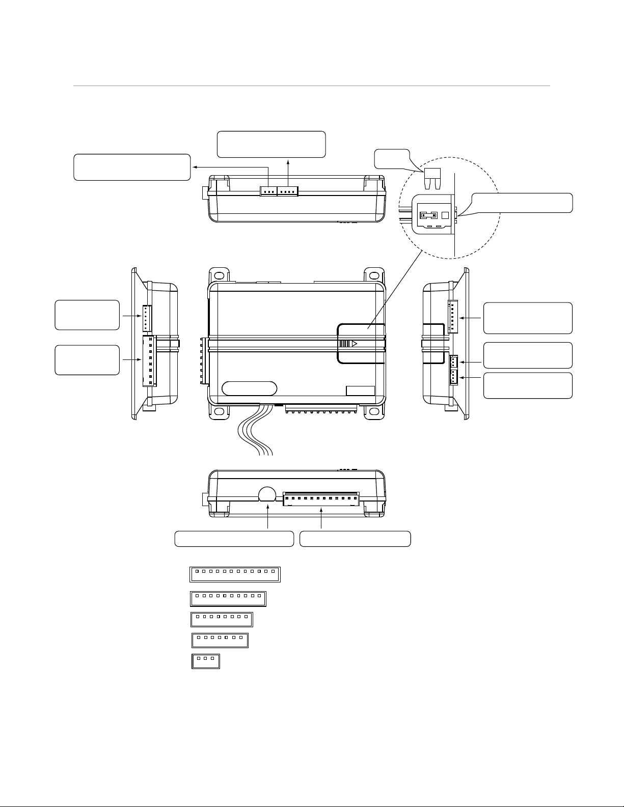
Wiring Diagram
+ -
(10A (MAXIMUM) FUSE JUMPER)
Bitwriter/Directed SmartStart
Port
Control Center
RF/Control
Center Port
D2D Port (for external
Directed interface module)
Note: Fuse is under the plastic cover
and needs to be installed for the
appropriate light flash polarity
10A FUSE
MINI ATM
Detail
(+) or (-) LIGHT FLASH POLARITY
Auxiliary 7-pin
Harness
Door Lock
8-pin Harness
Starter Disable Harness
1
1
1 8
12
10
Optional MUX Port
(GWA Zone 4)
Optional MUX Port
(Zone 7)
Main 12-pin Harness
5
71
1 3
© 2015 Directed. All rights reserved.
Page 6

Wiring Connections
Main Harness, White 12-pin connector
1 RED/WHITE (-) 200mA AUX/TRUNK RELEASE OUTPUT
2 RED (+)12VDC CONSTANT INPUT
3 BROWN (+) SIREN OUTPUT
4 WHITE/BROWN PARKING LIGHT ISOLATION WIRE - #87a of onboard relay
5 BLACK (-) CHASSIS GROUND
6 VIOLET (+) DOOR TRIGGER INPUT
7 BLUE (-) TRUNK PIN/ INSTANT TRIGGER INPUT (Programmable N/O or N/C)
8 GREEN (-) DOOR TRIGGER INPUT (Programmable N/O or N/C)*
9 BLACK/WHITE DOME LIGHT SUPERVISION/FLEX RELAY (Programmable) OUTPUT
10 WHITE/BLUE (-) 200mA AUX 1 OUTPUT
11 WHITE PARKING LIGHT OUTPUT
12 ORANGE (-) 500mA (GWA) GROUND WHEN ARMED OUTPUT
* When using the N/C (Normally Closed) setting, this wire only covers one door. Use AUX (Auxiliary)
outputs 2, 3 or 4 (as necessary) programmed as N/C door switch inputs (wired to each individual
door of the vehicle) to cover the other doors. The auxiliary outputs are also programmable as N/O
(Normally Open) door switch inputs so you can connect multiple doors without the use of diodes.
When the auxiliaries are programmed for these types of circuits and connected to the vehicle, the alarm
reports a door violation when triggered.
Important: NEVER connect the 200mA low current outputs directly to a motor or high current device
WITHOUT a relay.
Door Lock Harness, White 8-pin connector
1 VIOLET* UNLOCK #87 NORMALLY OPEN (INPUT)
2 BLUE/BLACK UNLOCK #30 COMMON (OUTPUT)
3 BROWN/BLACK UNLOCK #87a NORMALLY CLOSED
4 VIOLET/BLACK* LOCK #87 NORMALLY OPEN (INPUT)
5 GREEN/BLACK LOCK #30 COMMON (OUTPUT)
6 WHITE/BLACK LOCK #87a NORMALLY CLOSED
7 WHITE/VIOLET** DOME LIGHT SUPERVISION FLEX RELAY #87 NORMALLY OPEN (INPUT)
8 WHITE/BROWN** FLEX RELAY #87a NORMALLY CLOSED
* Violet and Violet/Black are common at the fuse holder.
** These wires work in conjunction with the 12-pin Black/White wire. The White/Violet determines what
the polarity of the 12-pin Black/White wire will be and the White/Brown will only be used if a five wire
isolation circuit is required.
Auxiliary Harness, White 7-pin connector
1 ORANGE/BLACK (-) 200mA AUX 4 OUTPUT
2 WHITE/BLACK (-) 200mA AUX 3 OUTPUT
3 VIOLET/BLACK (-) 200mA AUX 2 OUTPUT
4 LIGHT GREEN/BLACK (-) 200mA FACTORY ALARM DISARM OUTPUT
5 YELLOW (+) IGNITION INPUT
6 BROWN (-) 200mA HORN HONK OUTPUT
7 GRAY (-) HOOD PIN INPUT (Programmable N/O or N/C)
6
© 2015 Directed. All rights reserved.
Page 7
Important: NEVER connect the 200mA low current outputs directly to a motor or high current device
WITHOUT a relay.
Starter Disable Harness, White 3-pin connector
1 GREEN/WHITE STARTER - COMMON (KEY SIDE)
2 GREEN STARTER - NORMALLY OPEN (MOTOR SIDE)
3 GREEN/BLACK STARTER - NORMALLY CLOSED (MOTOR SIDE)
Sensor MUX Harness, Green 3-pin connector
1 RED +12V DC TO SENSOR
2 BLACK GND TO SENSOR
3 BLUE/WHITE MUX WIRE INPUT
D2D Harness, Red 4-pin connector
1 BLUE D2D - TX
2 BLACK (-) GROUND
3 GREEN D2d - RX
4 RED (+) 12V
Bitwriter/Directed SmartStart Harness, Black 3-pin connector
1 RED (+) 12V
2 ORANGE ESP 2 - RX/TX
3 BLACK (+) 12V
Wire Descriptions
Main Harness, 12-pin connector
Red/White: (-) AUX/TRUNK RELEASE OUTPUT
This (-) 200mA output is often used to operate a trunk/hatch release or other relay-driven functions. When
the system receives the command controlling trunk release (for longer than 1.5 seconds) the Red/White wire
will supply an output as long as the transmission continues. This output can also be programmed as an OEM
Alarm Arm or as a 2nd Unlock output (see AUX/Trunk Output Type in Feature Menus for more details).
Important: Never connect the 200mA low current outputs directly to a motor or high current device
WITHOUT a relay.
Red: (+) 12V CONSTANT INPUT
This wire supplies power to the unit’s micro-controller. Remove the supplied fuse before connecting to the (+)
terminal of the battery or another constant +12V supply. Make sure to replace the fuse once all connections
have been made.
Note: Always use a fuse within 12 inches of the point from which you obtain (+) 12V. Do not use the 15A
use in the harness for this purpose. This fuse protects the module only.
Brown: (+) SIREN OUTPUT
This wire is the (+) output for the siren. This wire connects to the (+) input of the siren.
White/Brown: PARKING LIGHTS FLASH ISOLATION WIRE (#87a of onboard relay)
This wire is a parking lights flash input from the vehicle light switch which connects to pin #87a of the onboard
lights flash relay. It is used for vehicles requiring light switch isolation during parking lights flash output.
7
© 2015 Directed. All rights reserved.
Page 8
For vehicles with multiplex light circuits which require a resistor, the onboard lights flash fuse can be replaced
+ -
with the specified resistor value (pay attention to appropriate circuit polarity). See the following diagram for
wiring information.
Multiplex Parking Lights
Light Switch
Multiplex wire
in vehicle
To Control
Module in
vehicle
X X
White/Brown
White
Note: Replace fuse with specified resistor value
if connecting to multiplex light circuit
(pay special attention to polarity selection)
LIGHT FLASH POLARITY
JUMPER Detail
Black: (-) CHASSIS GROUND
This wire is the unit’s source of ground. DO NOT connect this wire to any factory ground points; they can
cause noise and/or voltage drops which can affect system performance. Ground the unit and any accessories
to the same point in the vehicle (preferably the kick panel). Scrape away any paint and make your own
ground with a screw and a star washer.
Violet: (+) DOOR TRIGGER INPUT
This input wire is used in vehicles with (+) door trigger circuit and will sound the alarm when any of the
vehicle’s doors are opened.
Blue: (-) TRUNK TRIGGER/INSTANT TRIGGER INPUT N/O (Normally Open) OR N/C (Normally Closed)
This input wire comes factory set for use in vehicles with a (-) trunk trigger circuit and will sound the alarm
when the vehicle’s trunk is opened. It can also be used as an instant trigger input for use with a Directed single
zone sensor. This wire can be programmed for a N/O (Normally Open) or N/C (Normally Closed) circuit.
N/O = rests at ground when the trunk is OPEN, N/C = rests at ground when the trunk is CLOSED.
(see Trunk Switch Type in Feature Menus for more details).
Note: There are times when you need to temporarily bypass all sensor inputs to the unit, such as when
activating the trunk release or when adding an optional remote start to the system. Anytime an auxiliary
output is used, all trigger inputs (except the door trigger input) are bypassed for 5 seconds. During the 5
second period, if the system receives a (-) ground on the 12-pin Blue trunk trigger input wire, all trigger inputs
will remain bypassed until 5 seconds after the ground is removed from the Trunk trigger input wire. Refer to
the following diagrams for wiring/programming information.
8
© 2015 Directed. All rights reserved.
Page 9
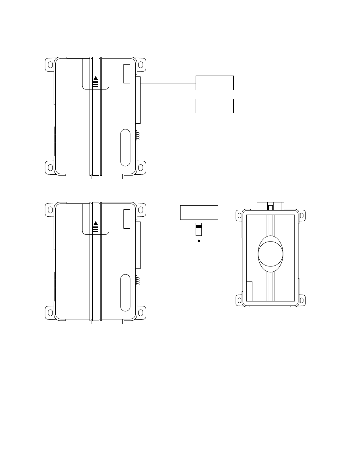
Trunk Release Sensor Shunt
Remote Start Sensor Shunt
(-) Trunk Pin Input
(-) Trunk Release Output
To (-) trunk pin
in vehicle
To trunk release
in vehicle
Remote Starter System
To (-) trunk pin in
vehicle (if used)
(-) Trunk Pin Input (-) Status Output
(-) AUX 1 or 4 Output * (-) Activation Input
(+) Ignition Output (to host alarm)
Ignition Input **
* AUX 1 or 4 must be programmed as Remote Start Report (see AUX 1 or AUX 4 Output Type in Feature
Menus for more details).
** Do not connect the ignition input of the system to the vehicle, connect to the Ignition Output of an add-on
Directed Remote Start System.
9
© 2015 Directed. All rights reserved.
Page 10
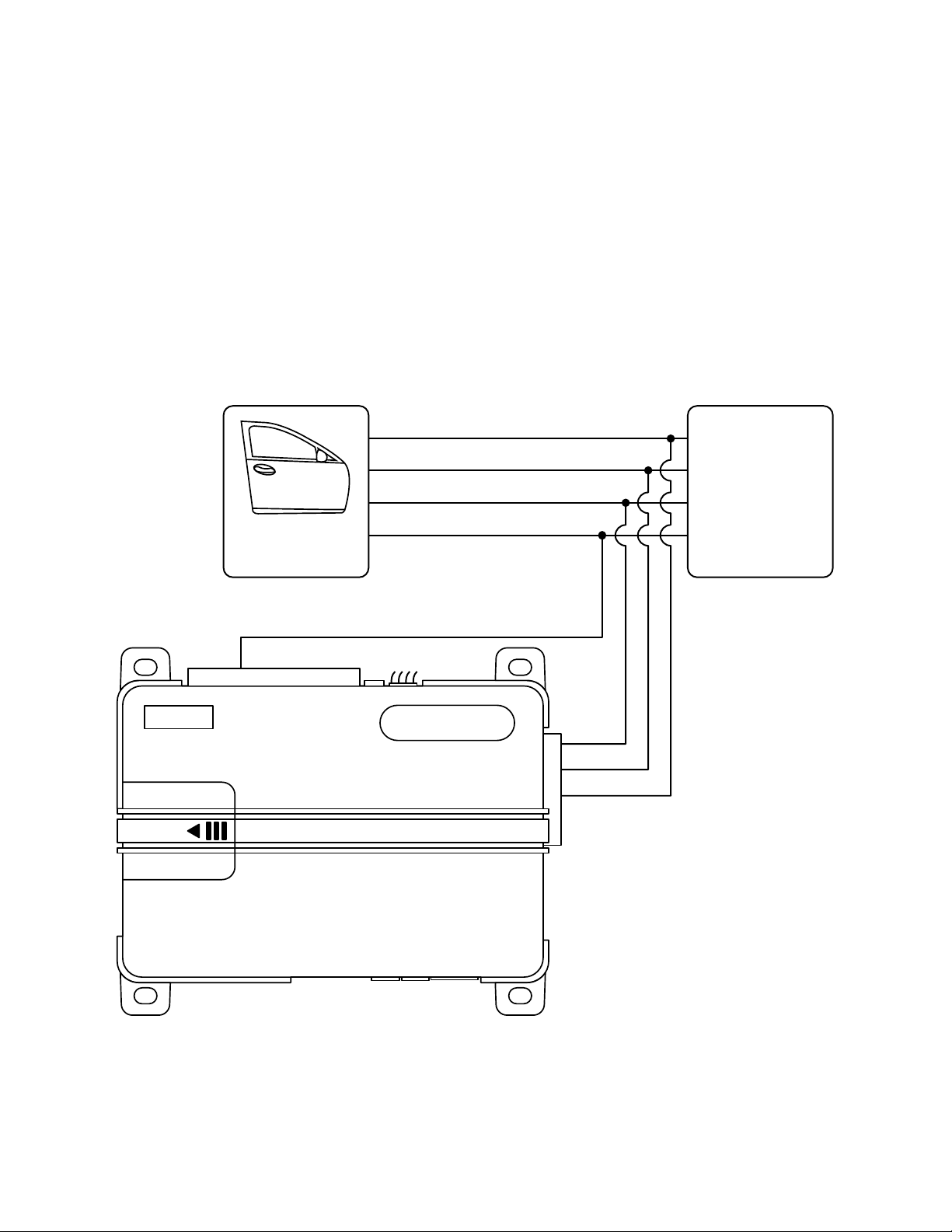
Green: (-) DOOR TRIGGER INPUT (N/O OR N/C)
This input wire comes factory set for use in vehicles with (-) door trigger circuit and will sound the alarm when
any of the vehicle’s doors are opened. This wire can be programmed for a N/O (Normally Open) or N/C
(Normally Closed) circuit.
N/O = rests at power or ground when the door is OPEN, N/C = rests at power or ground when the door is
CLOSED, (see Door Switch Type in Feature Menus for more details).
Note: This wire can only monitor one door when used in a Normally Closed circuit if all doors want to
be connected to individually, use AUX 2-4 outputs and refer to AUX Output Type in the Feature Menus for
programming to work with Normally Closed Door Trigger circuits. Refer to the following diagram for wiring
information.
N/C (Normally Closed) Door Triggers
RR Door Trigger
LR Door Trigger
RF Door Trigger
LF Door Trigger
Individual
Door Pins
Green Door Trigger Input*
BCM
AUX 2*
AUX 3*
AUX 4*
* Default is N/O and must be programmed for N/C
when connecting to Normally Closed door trigger circuits.
10
© 2015 Directed. All rights reserved.
Page 11
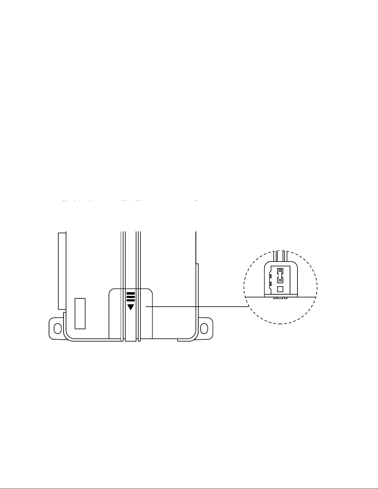
Black/White: DOME LIGHT/FLEX RELAY OUTPUT
+ -
This wire is pin #30 of the onboard Dome Light/Flex Relay and works in conjunction with the White/Violet
(pin #87) and the White/Brown (pin #87a) wires on the 8-pin Door Lock Harness.
This output is default to drive the dome light circuit in the vehicle. This output activates when disarming/
unlocking the system and when turning the ignition OFF in the vehicle (for programmable ON/OFF ignition
controlled dome light (see Ign-controlled Dome Light in Feature Menus for more details). The Flex Relay can
also be programmed as a Horn Honk or Trunk Release output (see Flex Relay in Feature Menus for more
details).
White/Blue: (-) AUXILIARY 1 OUTPUT
This (-) 200mA output is used for controlling any auxiliary function such as fuel door release or a window
module. This output can be programmed for different applications. (see AUX 1 options in Feature Menus for
more details).
Important: Never connect the 200mA low current outputs directly to a motor or high current device
WITHOUT a relay.
White: (+) or (-) PARKING LIGHTS OUTPUT
This wire should be connected to the parking lights wire in the vehicle. It activates when the system is armed/
disarmed and when the alarm is triggered. It can be set for a (-) or (+) output. See the following diagram for
setting the lights flash polarity.
(+) Parking Lights
LIGHT FLASH POLARITY
JUMPER Detail
Place the fuse in the correct
position for the desired polarity
Orange: (-) GWA (GROUND WHEN ARMED OUTPUT)
This wire supplies a (-) 500mA ground output as long as the system is armed. This output ceases as soon as
the system is disarmed. The GWA can be hooked up to a voice module or any accessory which requires a
ground when armed.
11
© 2015 Directed. All rights reserved.
Page 12

Door Lock Harness, 8-pin connector
Identifying the Door Lock System - Refer to Directed Tech Tip #1041: Door Locking Systems Wiring Guide for
more information. This system has onboard door lock relays and can be interfaced with most power door lock
systems drawing 15 amps or less.
Violet: UNLOCK RELAY PIN #87 (POLARITY INPUT)
This wire determines the polarity of the Blue/Black unlock output wire.
Note: This wire is connected to the Violet/Black Lock Relay Input wire, the connection is made at the fuse
holder.
Blue/Black: UNLOCK RELAY PIN #30 (OUTPUT)
This wire connects to the door unlock circuit in the vehicle. It can be programmed to unlock the vehicle when
the ignition is turned OFF, for a double pulse output and for output duration (see Ign-controlled Locks, Door
Lock Pulses or Door Lock Duration in Feature Menus for more details).
Brown/Black UNLOCK RELAY PIN #87A (ISOLATION WIRE)
This wire connects to the switch side of a 5-wire door unlock circuit.
Violet/Black: LOCK RELAY PIN #87 (POLARITY INPUT)
This wire determines the polarity of the Green/Black lock output wire.
Note: This wire is connected to the Violet Unlock Relay Input wire, the connection is made at the fuse holder.
Green/Black: LOCK RELAY PIN #30 (OUTPUT)
This wire connects to the door lock circuit in the vehicle. It can be programmed to lock the vehicle when the
ignition is turned ON, for a double pulse output and for output duration. Additionally this output may be used
for Comfort Closure for vehicles which can close the windows (and in some cases the sunroof) while holding
the key to the lock position in the door key cylinder (see Ign-controlled Locks, Door Lock Pulses, Door Lock
Duration or Comfort Closure in Feature Menus for more details).
Note: The doors of the vehicle must be closed when turning the ignition ON for the ignition controlled door
lock feature to work.
White/Black: LOCK RELAY PIN #87A (ISOLATION WIRE)
This wire connects to the switch side of a 5-wire door lock circuit.
White/Violet: DOME LIGHT/FLEX RELAY POLARITY INPUT
This wire is pin #87 of the onboard Dome Light/Flex Relay and works in conjunction with the White/Brown
(pin #87a) and the Black/White (pin #30) wires on the 8-pin Door Lock Harness and 12-pin Main Harness.
This input is used to determine the polarity output of the Black/White wire from the 12-pin Main Harness. The
Flex Relay activates when disarming/unlocking the system and when turning the ignition OFF in the vehicle
(for programmable ON/OFF ignition controlled dome light see Ign-controlled Dome Light in Feature Menus
for more details). The Flex Relay can also be programmed as a Horn Honk or Trunk Release output (eee Flex
Relay in Feature Menus for more details).
White/Brown: DOME LIGHT/FLEX RELAY ISOLATION WIRE
This wire is pin #87a of the onboard Dome Light/Flex Relay and works in conjunction with the White/Violet
(pin #87) and the Black/White (pin #30) wires on the 8-pin Door Lock Harness and 12-pin Main Harness.
This wire is used to isolate the dome light circuit in the vehicle and is typically used for 5-wire circuit. This
relay activates when disarming/unlocking the system and when turning the ignition OFF in the vehicle (for
programmable ON/OFF ignition controlled dome light see Ign-controlled Dome Light in Feature Menus for
more details). The Flex Relay can also be programmed as a Horn Honk or Trunk Release output (see Flex
Relay in Feature Menus for more details).
12
© 2015 Directed. All rights reserved.
Page 13

Auxiliary Harness, 7-pin connector
Orange/Black: (-) AUXILIARY 4 OUTPUT/INPUT
This (-) 200mA output is used for controlling any auxiliary function such as fuel door release or a window
module. This output can be programmed for different applications including a N/O or N/C door trigger
input. (see the AUX 4 Output Types in Feature Menus for more details).
White/Black: (-) AUXILIARY 3 OUTPUT/INPUT
This (-) 200mA output is used for controlling any auxiliary function such as fuel door release or a window
module. This output can be programmed for different applications including a N/O or N/C door trigger
input. (see the AUX 3 Output Types in Feature Menus for more details).
Violet/Black: (-) AUXILIARY 2 OUTPUT/INPUT
This (-) 200mA output is used for controlling any auxiliary function such as a fuel door release or a window
module. This output can be programmed for different applications including a N/O or N/C door trigger
input. (see the AUX 2 Output Types in Feature Menus for more details).
Green/Black: (-) FACTORY ALARM DISARM OUTPUT
This 200mA output is used to disarm the factory alarm and triggers when the system is disarmed and when
activating the trunk release output. It typically connects to the Factory Alarm Disarm wire in the vehicle. This
output can be programmed to activate with unlock, trunk release and for a single or double pulse output (see
OEM alarm Disarm Options in Feature Menus for more details).
Yellow: (+) IGNITION INPUT
Connect this wire to the (+) 12V ignition wire in the vehicle. This wire must show (+) 12V with the key in RUN
position and during cranking. Take care to insure that this wire cannot be shorted to the vehicle chassis at any
point. If you are adding a remote start to the system, the ignition input will not be connected to the vehicle
instead it will connect to the host system ignition output of the remote start (see the Remote Start Sensor Shunt
diagram on page 9 for wiring information).
Brown: (-) HORN HONK OUTPUT
This wire supplies a (-) 200mA output which can be used to honk the vehicle’s horn. This output pulses
when the alarm has been panicked or triggered. This output can be programmed to operate similar to the
siren output wire, it will generate a single pulse when lock the doors with the remote, and two pulses when
unlocking with the remote. (see Horn Function in Feature Menus for more details).
Gray: HOOD TRIGGER INPUT (N/O OR N/C)
This input wire is default for use in vehicles with a (-) hood trigger circuit and will sound the alarm when the
vehicle’s hood is opened. This wire can be programmed for a N/O (Normally Open) N/C (Normally Closed)
circuit.
N/O = rests at power or ground when the hood is OPEN, N/C = rests at power or ground when the hood
is CLOSED. (see Hood Switch Type in Feature Menus for more details).
Starter Disable Harness, 3-pin connector
Green/White: STARTER DISABLE RELAY COMMON PIN #30
This wire will be used in both the Normally Closed and Normally Open type of starter disable setups. This
wire connects to the Ignition Switch side of the cut starter wire in the vehicle.
Green: STARTER DISABLE RELAY NORMALLY OPEN PIN #87
This wire will be used in the Normally Open type of starter disable setup. This wire connects to the car side
of the cut starter wire in the vehicle. In the normally open setting, the vehicle cannot be started if the system
does not have power
13
© 2015 Directed. All rights reserved.
Page 14

Green/Black: STARTER DISABLE RELAY NORMALLY CLOSED PIN #87a
This wire will be used in the Normally Closed type of starter disable setup. This wire connects to the car side
of the cut starter wire in the vehicle. In the normally closed setting, the vehicle can be started if the system
does not have power.
Normally Closed Starter Disable
Starter Wire
Ignition Switch
X
* Cut *
X
To Starter
Not Used
Green/White
Green
Green/Black
Ignition Switch
Starter Wire
* Cut *
To Starter
X
X
Normally Open Starter Disable
Green/White
Green
Green/Black
Not Used
14
© 2015 Directed. All rights reserved.
Page 15

Sensor MUX Harness, 3-pin connector
Red: (+) 12v TO SENSOR
This wire supplies a constant (+) 12v to an additional sensor.
Black: GWA TO SENSOR
This wire supplies a (-) to an additional sensor and doe s not activate until the system is armed, similar to the
Orange Ground When Armed wire on the 12-pin harness. This wire works well for tilt sensors that require a
Ground When Armed or any sensor that you want to activate only while the system is armed.
Blue/White: (-) MUX (MULTIPLEX INPUT)
This input will work with Directed single stage or dual stage sensors. Inputs shorter than 0.8 seconds will
trigger the Warn Away response, while inputs longer than 0.8 seconds will trigger the full alarm sequence.
If installing a Directed dual stage sensor, connect both the Warn Away and full trigger wires of the sensor to
this input.
Adjusting the Doubleguard Shock Sensor
Note: When adjusting the on board Doubleguard shock sensor, the main unit must be in the final mounting
location that it will be in after the install is complete. Adjusting the sensor and then relocating the main unit
will require readjustment.
Note: The siren will emit 1 short and 1 long sound when maximum/minimum sensitivity is reached. At
minimum sensitivity level, the impact sensor is turned OFF.
Note: After each adjustment the sensitivity can be tested by cautiously impacting the vehicle with increasing
intensity. The siren will chirp to indicate the impact level required to fully trigger the alarm.
Adjustment using the optional 2-way LCD remote control:
1. With the main unit mounted in its permanent location, make sure the system is disarmed with the ignition
OFF and all entry points on the vehicle are closed.
2. Press and hold the button of the remote control until a long beep is emitted and
is displayed. (if programmed to operate two systems, ignore the car 1 or car 2 text and beeps at 3
seconds).
3. Release the button to view the main menu.
4. Press and release the button.
5. Press and hold the button until a long beep is emitted and the siren emits a long chirp. The current
sensitivity
6. Adjust the sensitivity:
a. Press and release the and buttons change the sensitivity.
b. Press and hold the button. The adjustment is sent to the system and the remote control emits a long
beep as confirmation.
c. Release the button.
Exit adjustment mode:
• Press and release the button anytime to exit adjustment mode, and then press and hold to
return the remote control to normal operation (transmit LED turns OFF).
• Open the hood or trunk
• Turn the ignition ON
• Wait for 30 seconds between steps
• The siren will emit one long chirp when exiting adjustment mode.
Sen ##
is displayed, adjustment mode is ready.
Sensor Adjust
Setup Remote
is displayed.
is displayed.
Main Menu
15
© 2015 Directed. All rights reserved.
Page 16

Adjustment using the optional 2-way LED or 1-way remote control:
1. Make sure the system is disarmed with the ignition OFF and all entry points on the vehicle are closed.
2. Press and hold the button of the remote control for 8 seconds until the transmit LED turns ON then
release it (If programmed to operate two systems, ignore the transmit LED flashes at three seconds).
3. Press and hold the button until the transmit LED flashes OFF then ON and the siren emits a long
chirp. Adjustment mode is ready.
4. Adjust the sensitivity:
• Press and release the button to increase the sensitivity. The siren chirps two times.
• Press and release the
• Press and release the button to reset sensitivity to default setting. The siren chirps three times.
Exit adjustment mode:
• Press and release the
return the remote control to normal operation (transmit LED turns OFF).
• Open the hood or trunk
• Turn the ignition ON
• Wait for 30 seconds between steps
• The siren will emit one long chirp when exiting adjustment mode.
button to decrease the sensitivity. The siren chirps one time.
button any time to exit adjustment mode, and then press and hold to
Pairing a Remote Control
Pairing a remote control is a process whereby the remote control and the system in the vehicle learn each
other’s encrypted identification, securing their communication from intruders. Please note the remote control(s)
come already paired from the factory. These instructions can be used if reprogramming or adding a new
remote control to the system. The following instructions steps you through pairing the 2-way (optional) and
1-way remote control(s).
Note: Both the remote control and the vehicle need to be setup to pair a remote to the system and the
remote must be set to the desired Car1 or Car2 mode. (see Owners Manual for more detailss about selecting
vehicles).
LCD 2-Way Remote Control:
1. Press and hold the button on the remote for 8 seconds, the remote beeps once,
displayed on the screen. Release the button.
2. Press and release the button or the button until
3. Press and hold the button until the remote beeps 3 times then release the button. The remote is
now ready to pair with the system.
Vehicle Setup for Pairing:
• Open the vehicle door.
• Turn ON the vehicles ignition to the RUN position.
• Within 5 seconds press and release the Control Center button on the Control Center one time then
press it once more and hold it.
• The Control Center LED begins flashing in a single flash pattern and the siren will chirp once to
confirm the system is in pairing mode.
• Now release the Control Center Button.
4. With both the remote and system in pairing mode, press the button on the remote.
5. The siren chirps to indicate the system has learned the remote ID and is sending its ID to the 2-way
remote.
6. The LCD remote control will indicate a
go back to the
Once the remote has paired to the system
emit several tones to confirm.
Pair
screen, press the button on the remote again to attempt another pairing.
Successful
Successful
or
Pair
is displayed on the screen.
Failed
will display on the remote screen and it will also
pairing. If pairing fails, the remote will
Main Menu
is
Page 17

7. Once the pairing is completed turn OFF the ignition in the vehicle, the siren will sound to confirm
exiting. When both the system and remote have exited the Pairing Mode, you may now test for
functionality.
To exit Pairing Mode on the remote:
• Wait 30 seconds without pressing a button on the remote.
• Press and release the
button on the remote.
To exit Pairing Mode on the system:
• Turn OFF the ignition.
• Close the open door.
• Wait 60 seconds for the system to automatically exit.
• The siren will sound to confirm exiting.
LED 2-way or 1-way Remote Control:
1. Press and hold the button on the remote for 8 seconds. The transmit LED on the remote will come
ON solid, release the button.
2. Press and hold the button on the remote until the transmit LED flashes 3 times then comes ON
solid. The remote is now ready to pair with the system.
Vehicle Setup for Pairing:
• Open at least 1 vehicle door.
• Turn ON the vehicles ignition to the RUN position.
• Within 5 seconds press and release the Control Center button on the Control Center one time then
press it once more and hold it.
• The Control Center LED will begins flashing in a single flash pattern and the siren will chirp once to
confirm the system is in pairing mode. You may now release the Control Center Button.
3. With both the remote and system in pairing mode, press the button on the remote. The siren chirps
to indicate the system has learned the remote ID and is sending its ID to the 2-way remote (the 2-way
remote will emit several tones to indicate the remote has learned the system ID, the 1-way remote does
not offer confirmations).
4. If pairing fails, press the button on the remote again to attempt another pairing.
5. Once the pairing is completed turn OFF the ignition in the vehicle, the siren will sound to confirm
exiting. When both the system and remote have exited the Pairing mode, you may now test for
functionality.
To exit Pairing Mode on the remote:
• Wait 30 seconds without pressing a button on the remote.
• Press and release the button on the remote one time and press and hold again for 2 seconds,
the transmit LED on the remote will shut OFF to confirm exiting.
To exit Pairing Mode on the system:
• Turn OFF the ignition.
• Close the open door.
• Wait 60 seconds for the system to automatically exit.
• The siren will sound to confirm exiting.
17
© 2015 Directed. All rights reserved.
Page 18

Basic Remote Functions
Button
Level
Direct Access
Arm/Lock (Panic) Silent Mode Arm Sensor Bypass Sensor Silent Arm Full Silent Arm
Disarm/Unlock Silent Mode Disarm Remote Valet Car Finder
Remote Start*/AUX 1/4**
AUX/Trunk Release AUX 1 AUX 2 AUX 3 AUX 4
Advance Level Change Car (Hold
3s), Enter programming (Hold 8s)
x 1
LEVEL 1
x 2
LEVEL 2
Arm Status
(2-way only)
x 3
LEVEL 3
x 4
LEVEL 4
* Available only with optional Remote Start module installation
** This button can command either AUX 1 or AUX 4 if turned ON by an authorized Directed dealer.
Note: See owner’s guide of your specific model for exact functionality as some functions may differ to those
shown above.
Important: If the Control Center has been replaced, all remote controls must be re-paired with the system.
VRS (Vehicle Recovery System)
When VRS is enabled and the vehicle is stolen or carjacked, VRS sounds the siren and flashes the parking
lights to persuade the thief to abandon the vehicle, and when the ignition is turned off, activates the starter
disable to prevent the engine from restarting.
To arm VRS:
• Perform the silent mode arm command while driving, or while the ignition is turned ON. The siren
chirps and parking lights flash once to confirm arming. The arm LED and beeps play to confirm
arming.
Note: If Valet mode is ON, the LED and fault tone plays, exit Valet mode before arming VRS.
• Once armed, VRS triggers if any door is opened then closed while the ignition is ON, and if the
vehicle is parked while armed, VRS triggers when driving resumes. See trigger description below.
• When triggered, the Control Center LED begins flashing after fifteen seconds. Within 45 seconds
perform the silent mode arm command to disarm VRS.
Note: If not disarmed, the siren begins chirping for 60 seconds and then becomes a constant siren blast
with flashing parking lights for several minutes. This output will continue and be repeated each time the
ignition is turned ON until VRS is disarmed.
To disarm VRS:
• Perform the silent mode disarm command on the remote anytime before VRS has been triggered, or
within one minute after it has triggered and before the siren begins to chirp.
Note: If not disarmed before the siren begins to chirp, the emergency override procedure must be used
to disarm VRS. (see owners guide for override procedure).
18
© 2015 Directed. All rights reserved.
Page 19

Programming System Features
The System Features Learn Routine dictates how the unit operates. It is possible to access and change most of
the feature settings using the Control Center button.
Programming a System Feature:
1. Open a door.
2. Turn the ignition ON, then OFF.
3. Select a Menu. Press and hold the Control Center button. The number of siren chirps indicates the
Menu number. 1 chirp indicates Menu 1, 2 chirps for Menu 2.
4. When the desired Menu chirps are heard, release the Control Center button.
5. Select a Feature. Press and release the Control Center button the number of times corresponding
to the feature desired to change. Then press and hold one more time to select the feature. Do not
release the Control Center button.
6. Program the Feature. While holding the Control Center button, program the feature using the remote
control.
For features with only two options;
For features with more than two options;
descending order.
Note: Pressing button resets the feature to the factory default.
Once a feature is programmed:
• Other features can be programmed within the same Menu.
• Another Menu can be selected.
• The Learn Routine can be exited if programming is complete.
To access another feature in the same Menu:
1. Press and release the Control Center button the number of times necessary to advance from the
feature just programmed to the next one desired to program.
2. Then press the Control Center button once more and hold it.
To select another Menu:
1. Press and hold the Control Center button.
2. After 3 seconds, the unit advances to the next Menu, the siren chirps, indicating which menu has been
accessed.
The learn routine exits if any of the following occurs:
• The open door is closed.
• The ignition is turned ON.
• There is no activity for 30 seconds.
• The Control Center button is pressed too many times.
= option 1, while = option 2.
selects the options in ascending order, while selects them in
19
© 2015 Directed. All rights reserved.
Page 20

Feature Menus
Default settings are Opt. 1.
Menu 1 - Vehicle Integration
Item Feature
1 System Arming Mode
2 Panic Mode*
3 Confirmation Chirps
4 Siren Duration
(seconds)
5 Ign-controlled Locks
6 Door Lock Pulses
7 Door Lock Output
Duration (seconds)
8 Ignition-controlled
2nd Unlock**
9 Comfort Closure*
10 Horn Function
(milliseconds)
11 Hood Switch type
12 Trunk Switch Type
13 Door Switch Type
14 Starter Disable Type
15 Sensor Trigger
16 Nuisance Prevention
17 Flex Relay
18 VRS
19 Remote Button unlock
(Ign OFF)*
Opt. 1
Active
ON
ON - Warn Away
chirps ON
30 sec.
No Ign-locking
Single
0.8 sec.
Delayed 2nd unlock
ON/Ign-control
after first unlock
No Comfort Closure
Full Alarm Only
Normally
Open
Normally
Open
Normally
Open
Normally
Closed
Single Sensor
ON
Domelight
OFF
ON
* Not available with the 1-way remote control.
** Requires an AUX channel Output Type to be programmed as a 2nd Unlock output (see Menu 2).
Opt. 2 Opt. 3 Opt.4 Opt. 5+
Passive Arm – no lock Passive Arm
Ignition OFF Only OFF
ON - Warn Away
chirps OFF
60 sec.
Lock & Unlock Lock Only Unlock Only
Double Unlock Only Double Lock
3.5 sec. 0.4 sec.
Immediate 2nd unlock
ON/Ign-control after
first unlock
Comfort Closure 1 Comfort
Siren Function 20 ms Siren Function
Normally closed
Normally
Closed
Normally
Closed
Normally
Open
Double sensor
OFF
Horn Trunk release
ON - Disarm chirps
OFF
OFF
& lock
OFF - Warn
Away chirps
ON
Only
Closure 2
30 ms
ON - Disarm
chirps ON
Auto Re-arm no lock
OFF - Warn
Away chirps
OFF
Double Lock
& Unlock
Siren Function
40 ms
Auto
Re-arm & Lock
Siren Function
50 ms
1. System Arming mode:
1. Active: the transmitter must be used to arm the system.
2. Passive Arm w/o lock: after exiting the vehicle the system will automatically arm. The doors will not
lock.
3. Passive Arm w/lock: after exiting the vehicle the system will automatically arm and lock the doors.
4. Auto re-arm w/o lock: if the vehicle is not entered after receiving a disarm command, the system will
automatically re-arm. The doors will not lock.
5. Auto re-arm w/lock: if the vehicle is not entered after receiving a disarm command, the system will
automatically re-arm and lock the doors.
20
© 2015 Directed. All rights reserved.
Page 21

2. Panic Mode:
1. ON: the Panic output can be activated at any time.
2. Ign. OFF Only: the Panic output can be activated only when the ignition is OFF.
3. OFF: the Panic output is defeated.
3. Confirmation Chirps:
1. ON w/Warn Chirps ON: arm, disarm, and sensor Warn Away chirps are active.
2. ON w/Warn Chirps OFF: arm and disarm chirps are active, Warn Away chirps are defeated.
3. OFF w/Warn Chirps ON: arm and disarm chirps are defeated, Warn Away chirps are active.
4. OFF w/Warn Chirps OFF: arm, disarm, and sensor Warn Away chirps are defeated.
4. Siren Duration:
1. 30sec: the siren output duration for full trigger activations and Panic mode is 30 seconds.
2. 60sec: the siren output duration for full trigger activations and Panic mode is 60 seconds.
5. Ign-controlled Locks:
1. No Ign-locking: the door lock/unlock outputs will not activate when ignition is turned ON & OFF.
2. Lock & Unlock: the door lock & unlock output will activate when ignition is turned ON & OFF.
3. Lock Only: the door lock output will activate when ignition is turned ON.
4. Unlock Only: the door unlock output will activate when ignition is turned OFF.
6. Door Lock Pulses:
1. Single: the door lock & unlock outputs will pulse once.
2. Double Unlock only: the unlock output only will pulse twice.
3. Double Lock Only: the lock output only will pulse twice.
4. Double Lock & Unlock: the lock & unlock outputs will pulse twice.
7. Door Lock Output Duration:
1. 0.8 sec.: the door lock output pulses will be 800 milliseconds in duration.
2. 3.5 sec.: the door lock pulses will be 3.5 seconds in duration.
3. 0.4 sec.: the door lock pulses will be 400 milliseconds in duration.
8. Ignition Controlled 2nd Unlock:
1. Delayed: for Ign-controlled unlocking, the 2nd Unlock will activate 800 milliseconds after the first
(driver door) unlock.
2. Immediate: for Ign-controlled unlocking, the 2nd Unlock will activate at the same time as the first
(driver door) unlock.
9. Comfort Closure:
1. No comfort Closure: Comfort Closure is defeated when arming.
2. Comfort Closure 1: When arming, the door lock pulse (or 2nd pulse for double pulses) will remain
ON for 20 seconds.
3. Comfort Closure 2: When arming, 800 milliseconds following the end of the door lock pulse (or 2nd
pulse for double pulses); the door lock output will turn ON again for 20 seconds.
10. Horn Function:
1. Full Alarm Only: the horn output will pulse only during full trigger events.
2. Siren Function 20/30/40/50 milliseconds: The horn output will emulate the siren output with
selectable output timing to compensate for OEM horn inefficiency.
21
© 2015 Directed. All rights reserved.
Page 22

11. Hood Switch Type:
1. Normally Open: for vehicles with a hood switch that rests at power or ground when the hood is
OPEN.
2. Normally Closed: for vehicles with a hood switch that rests at power or ground when the hood is
CLOSED.
12. Trunk Switch Type:
1. Normally Open: for vehicles with a trunk switch that rests at power or ground when the trunk is
OPEN.
2. Normally Closed: for vehicles with a trunk switch that rests at power or ground when the trunk is
CLOSED.
13. Door Switch Type:
1. Normally Open: for vehicles with door switches that rest at power or ground when the door is
OPEN.
2. Normally Closed: for vehicles with door switches that rest at power or ground when the door is
CLOSED.
14. Immobilizer Type:
1. Normally Open: the starter disable relay will rest OPEN when main power is disconnected.
2. Normally Closed: the starter disable relay rests CLOSED when main power is disconnected.
15. Sensor Full Trigger:
1. Single: full trigger activation of only one sensor is required to fully trigger the alarm.
2. Double: full trigger activation of two sensors within a ten second period is required to fully trigger
the alarm.
16. NPC (Nuisance Prevention):
1. ON: sensors that trigger excessively will be defeated until they have been stable for more than one
hour.
2. OFF: sensors will not be defeated if triggered excessively.
17. Flex Relay:
1. Dome: the 12-pin Black/White wire will operate as Dome Light Supervision.
2. Horn: the 12-pin Black/White wire will operate as Horn Honk Output; the 7-pin Brown wire will
operate as Dome Light Supervision.
3. Trunk: the 12-pin Black/White wire will operate as Trunk Release Output; the 12-pin Red/White
wire will operate as Dome Light Supervision.
18. VRS (Vehicle Recovery System):
1. OFF: The Vehicle Recovery System is disabled.
2. ON – Disarm chirps OFF: The Vehicle Recovery System is enabled and, when disarmed by Remote
Control, will not chirp the siren.
3. ON – Disarm chirps ON: The Vehicle Recovery System is enabled and, when disarmed by Remote
Control, will chirp the siren 3 times to confirm.
19. Remote Button Unlock (Ign. OFF):
1. ON: a message telling the 2-way remote control to unlock the keypad is sent each time the vehicle
ignition is turned OFF.
2. OFF: no message is sent.
Note: This feature works in conjunction with the keypad lock feature of the remote control.
22
© 2015 Directed. All rights reserved.
Page 23

Menu 2 - Convenience
Item Feature
1 One-time Bypass
2 Override Pulse count
3 Door Trigger Error Chirp
4 Ign-controlled Dome light
5 OEM Alarm Disarm
w/AUX-Trunk
6 OEM Alarm Disarm Output
7 OEM Alarm Disarm Pulses
8 AUX/Trunk Output type
9 AUX/Trunk Linking
10 AUX 1 Output type
11 AUX 1 Linking
12 AUX 2 Output Type
13 AUX 2 Linking
Opt. 1
One-time
bypass OFF
1
ON
ON
ON
With Unlock
1
Validity
No Linking
Validity
No Linking
Validity
No Linking
Opt. 2 Opt. 3 Opt.4 Opt. 5+
One-time
bypass ON
2 3 4 5
OFF
OFF
OFF
Before Unlock
2
OFF OEM Alarm
Arm
Link to Arm Link to Disarm Link to Arm/
Latch Latch/reset/
ign
Link to Arm Link to Disarm Link to Arm/
Latch Latch reset/
ign
Link to Arm Link to Disarm Link to Arm/
2nd unlock
Disarm
Timed OFF (5) OEM Alarm Arm
(6), 2nd Unlock (7),
Remote Start Report* (8)
disarm
Timed OFF (5) OEM Alarm Arm
(6), 2nd Unlock (7),
N/O Door Switch (8),
N/C Door Switch (9)
Disarm
14 AUX 3 Output Type
15 AUX 3 Linking
16 AUX 4 Output Type
17 AUX 4 Linking
18 Remote Start Button Control
Validity
No Linking
Validity
No linking
None**
Latch Latch reset/
ign
Link to Arm Link to Disarm Link to Arm/
Latch Latch reset/
ign
Link to Arm Link to Disarm Link to Arm/
AUX 1 AUX 4
Timed OFF (5) OEM Alarm Arm
Disarm
Timed OFF (5) OEM Alarm Arm
Disarm
(6), 2nd Unlock (7),
N/O Door Switch (8),
N/C Door Switch (9)
(6), 2nd Unlock (7),
N/O Door Switch (8),
N/C Door Switch (9)
Remote Start Report* (10)
* The "Remote Start" button on the remote will activate AUX 1 or AUX 4 (see Menu Item 18).
**When programming with the Bitwriter, this option is labeled "Normal".
1. One-time Bypass:
1. OFF: One-Time Bypass is not available.
2. ON: the One-Time Bypass feature will defeat Passive Arming once and, if Armed by remote control,
will defeat Comfort Closure and AUX outputs linked to Arming.
2. Override Pulse Count:
• 1-5: sets the number of presses (1-5) on the Control Center Button required to override the alarm
system if a remote is damaged or not available.
23
© 2015 Directed. All rights reserved.
Page 24

3. Door Trigger Error Chirp:
1. ON: if the door trigger is active when arming, the siren will emit a second chirp and a message will
be sent to the 2-way remote control as an alert if equipped.
2. OFF: an active door trigger when arming will not create an alert output.
4. Ign-controlled Dome light:
1. ON: the dome light supervision output will activate when the ignition is turned OFF.
2. OFF: the dome light supervision output will not activate when the ignition is turned OFF.
5. OEM Alarm Disarm w/AUX/Trunk (Lt. Green/Black, 7-pin harness):
1. ON: the OEM Alarm Disarm wire will pulse as programmed when the AUX/Trunk output is
activated.
2. OFF: the OEM Alarm Disarm wire will not pulse when the AUX/Trunk output is activated.
6. OEM Alarm Disarm Output (Lt. Green/Black, 7-pin harness):
1. With Unlock: the OEM Alarm Disarm wire will pulse as programmed at the same time as the unlock
(Blue) wire.
2. Before Unlock: the OEM Alarm Disarm wire will pulse as programmed before the unlock wire.
7. OEM Alarm Disarm Pulses (Lt. Green/Black, 7-pin harness):
1. The OEM Alarm Disarm wire will pulse once per operation.
2. The OEM Alarm Disarm wire will pulse twice per operation.
8. AUX/Trunk Output Type:
• Refer to AUX 1 Output Type descriptions.
9. AUX/Trunk Linking:
• Refer to AUX 1 Linking descriptions.
10. AUX 1 Output Type:
1. Validity: when the AUX command is received the output will turn ON and remain ON until the
command ceases.
2. Latch: when the AUX command is received the output will turn ON and remain ON until the
command is received again.
3. Latch/Reset/Ignition: when the AUX command is received the output will turn ON and remain ON
until the command is received again or the ignition is turned ON/OFF.
4. Timed: when the AUX command is received the output will turn ON for the programmed time
duration (default 30sec.).
5. OFF: the output will not activate for a remote control command, use this option when the AUX
command controls an external device such as a garage door module.
6. OEM Alarm Arm: the output will not activate for a remote control command, it will pulse when the
system arms to activate the OEM alarm system.
7. 2nd Unlock: the output will operate as 2nd Unlock and will only activate when pressing the unlock
button on the remote within ten seconds of disarming the system with the remote.
8. Remote Start Report: the output will pulse once to activate an add-on remote start module and the 12
pin trunk input wire will be monitored for a ground input to confirm remote start activation (2-way
remote only) or to shunt connected sensors. The "Remote Start" button on the remote will activate
AUX 1 or AUX 4 (see Menu Item 18)
11. AUX 1 Linking:
1. No Linking: the AUX output will not activate for a remote control command.
2. Link to Arm: the AUX output will activate for the Arm command.
3. Link to Disarm: the AUX output will activate for the Disarm command.
4. Link to Arm/Disarm: the AUX output will activate for the Arm & Disarm commands.
24
© 2015 Directed. All rights reserved.
Page 25

12. AUX 2 Output Type:
1. Validity: refer to AUX 1 output type description.
2. Latch: refer to AUX 1 output type description.
3. Latch/reset/Ignition: refer to AUX 1 output type description.
4. Timed: refer to AUX 1 output type description.
5. OFF: refer to AUX 1 output type description.
6. OEM alarm arm: refer to AUX 1 output type description.
7. 2nd unlock: refer to AUX 1 output type description.
8. N/O door switch: for vehicles with multiple door switches that rest at power or ground when the
door is OPEN.
9. N/C door switch: for vehicles with multiple door switches that rest at power or ground when the
door is CLOSED.
13. AUX 2 Linking:
• Refer to AUX 1 Linking description.
14. AUX 3 Output Type:
1. Validity: refer to AUX 1 output type description.
2. Latch: refer to AUX 1 output type description.
3. Latch/reset/Ignition: refer to AUX 1 output type description.
4. Timed: refer to AUX 1 output type description.
5. OFF: refer to AUX 1 output type description.
6. OEM alarm arm: refer to AUX 1 output type description.
7. 2nd unlock: refer to AUX 1 output type description.
8. N/O door switch: refer to AUX 2 output type description.
9. N/C door switch: refer to AUX 2 output type description.
15. AUX 3 Linking:
• Refer to AUX 1 Linking description.
16. AUX 4 Output Type:
1. Validity: refer to AUX 1 output type description.
2. Latch: refer to AUX 1 output type description.
3. Latch/reset/Ignition: refer to AUX 1 output type description.
4. Timed: refer to AUX 1 output type description.
5. OFF: refer to AUX 1 output type description.
6. OEM alarm arm: refer to AUX 1 output type description.
7. 2nd unlock: refer to AUX 1 output type description.
8. N/O door switch: refer to AUX 2 output type description.
9. N/C door switch: refer to AUX 2 output type description.
10. Remote start report: refer to AUX 1 output type description.
17. AUX 4 Linking:
• Refer to AUX 1 Linking description.
18. Remote start button control:
1. None: The
button has no function.
2. AUX 1: The button will command AUX 1.
3. AUX 4: The button will command AUX 4.
25
© 2015 Directed. All rights reserved.
Page 26

Bitwriter - Only Options
If programming with the Bitwriter or XKLoader 3, the Learn Routine can be locked or unlocked. If the
Learn Routine has previously been locked, it must be unlocked with Bitwriter - this cannot be done
manually with the Control Center button.
The Bitwriter
or XKLoader 3 gives you access to a wider range of system options. These features and the
adjustments that may be programmed are described in the table below.
Item Feature
1 Siren Duration (seconds)
2 Shock Sensor Level
3 Zone 4 Sensor Icon Type*
4 Zone 7 Sensor Icon Type*
5 AUX/Trunk Remote Icon type*
6 AUX 1 Timed Output (seconds)
7 AUX 1 Remote Icon type*
8 AUX 2 Timed Output (seconds)
9 Remote AUX 2 Icon type*
10 AUX 3 Timed Output (seconds)
11 Remote AUX 3 Icon type*
12 AUX 4 Timed Output (seconds)
13 Transmitter Programming
14 Feature Programming
Default
30 sec.
7
None
None
Trunk
30 sec.
Pulsed
30 sec.
Pulsed
30 sec.
Pulsed
30 sec.
Unlocked
Unlocked
Opt. 2 Opt. 3 Opt.4 Opt. 5+
Options: 1 to 180 sec.
Options: 0 to 15 in increments of 1
Shock Sensor Field
Disturbance
Shock Sensor Field
Disturbance
Windows Sunroof Audio Lights/Left dr./
Options: 1 to 90 sec.
Trunk Window Sunroof Audio/Lights/
Options: 1 to 90 sec.
Trunk Window Sunroof Audio/Lights/
Options: 1 to 90 sec.
Trunk Window Sunroof Audio/Lights/
Options: 1 to 90 sec.
Locked
Locked
* Feature only available for the LCD 2-way remote control with display screens.
Tilt Sensor Glass Break/
Ultrasonic/Sensor
Tilt Sensor Glass Break
Ultrasonic/Sensor
Right dr./
Rear Hatch
Left dr./Right dr./
Rear Hatch/
Timed/ Latched
Left dr./Right dr./
Rear Hatch/
Timed/ Latched
Left dr./Right dr./
Rear Hatch/
Timed/ Latched
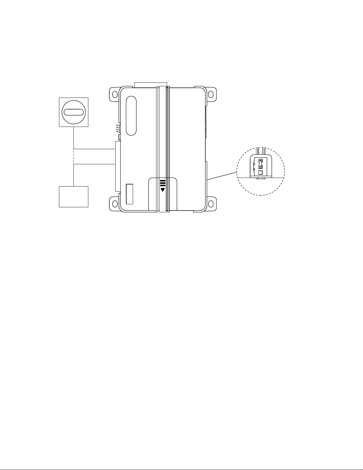
Note: The Bitwriter is a hand held Feature Programming tool that can be used to fine tune and access certain
features that are not accessible with manual programming. The Bitwriter plugs into black 3-pin plug on the
system. The black 3-pin port will also be utilized by the optional Smartstart module when applicable.
26
© 2015 Directed. All rights reserved.
Page 27

1. Siren Duration: sets the Full Trigger output duration in 1 second intervals up to 180 seconds.
2. Sensor 1 level: directly sets the sensor level of the onboard shock sensor
3. Zone 4 Sensor Icon Type: sets the Zone 4 (Sensor 2) name to be displayed in the Text Field for Warn
Away and Full Trigger activations
4. Zone 7 Sensor Icon Type: sets the Zone 7 (Sensor 3) name to be displayed in the Text Field for Warn
Away and Full Trigger activations
5. AUX/Trunk Icon Type: sets the name to be displayed in the text field when the AUX/Trunk output is
activated/de-activated
6. AUX 1 Timed Output: sets the output duration in 1 second intervals up to 90 seconds for AUX 1
7. AUX 1 Icon Type: sets the Accessory name to be displayed in the text field when the AUX 1 output is
activated/de-activated
8. AUX 2 Timed Output: sets the AUX 2 “Timed” output in 1 second intervals up to 90 seconds
9. AUX 2 Icon Type: sets the Accessory name to be displayed in the text field when the AUX 2 output is
activated/de-activated
10. AUX 3 Timed Output: sets the AUX 3 “Timed” output in 1 second intervals up to 90 seconds
11. AUX 3 Icon Type: sets the Accessory name to be displayed in the text field when the AUX 3 output is
activated/de-activated
12. AUX 4 Timed Output: sets the AUX 4 “Timed” output in 1 second intervals up to 90 seconds
13. Feature Programming: locks and unlocks the user’s ability to enter the feature menus and manually
change the main unit programming using the Control Center
14. Transmitter Programming: locks and unlocks the user’s ability to enter the remote control/Reset menu and
manually change any functions using the Control Center
Reset and Deletion
If a feature needs to be reset or the remote controls need to be deleted, use the following procedure:
1. Open a door.
2. Turn the ignition to the ON position.
3. Within 10 seconds, press and release the Control Center button 2 times if you want to delete remote
controls or 3 times to reset features. These function steps are described next.
• Delete remote controls: This feature erases all remote controls from the memory of the security system.
This is useful in cases when a customer’s remote is lost or stolen.
Note: This does not reset the programmed features of the security system.
• Reset Features: This resets all features of the security system to the factory default settings.
Note: This feature does not delete the remote controls from the security system.
4. Once you have selected the function step, press the Control Center button once more and hold it. The
LED flashes and the siren chirps to confirm the selected functional step. Do not release the Control
Center button
5. While holding the Control Center button, press the button on a programmed remote control. The siren
chirps to confirm that the remote controls have successfully been deleted or the features have been reset.
6. Once the feature is reset, the Control Center button can be released.
27
© 2015 Directed. All rights reserved.
Page 28

Long Term Event History
The system stores the last six full triggers in memory. These are not erasable. To access long term event history:
1. With the ignition OFF, press and hold the Control Center button.
2. Turn the ignition ON.
3. Release the Control Center button.
4. Within 5 seconds, press and release the Control Center button. The status LED flashes in groups
indicating the last six zones that triggered the unit for 1 minute or until the ignition is turned OFF (indicated
in the order of most recent first to oldest last). Refer to Table of Zones for trigger information.
Note: The Warn Away triggers are not stored to memory and is not reported.
Table of Zones
A zone is represented by the number of status LED flashes used by the system to identify a particular type of
input.
Zone Description Input Description
1 Trunk Pin 12-pin Blue wire
2 Instant trigger: a heavier impact detected by the onboard shock sensor Onboard shock sensor.
3 Door switch trigger 12-pin Green or Violet wire
4 Instant trigger: For optional sensors 3-pin optional GWA MUX port
5 Ignition trigger 7-pin Yellow wire
6 Hood Pin 7-pin Gray wire
7 Instant trigger: For optional sensors 4-pin optional MUX port
Troubleshooting: Alarm
Shock sensor doesn’t trigger the alarm:
1. Was the onboard shock sensor adjusted before the brain was mounted? If so re-adjust the sensor.
2. Has the onboard shock sensor been turned OFF? The sensor has the ability to be turned OFF when
adjusting.
3. Has the NPC system been triggered? If so, you hear 5 chirps when disarming. To check this, turn the
ignition key ON and OFF to clear the NPC memory, and then retest the shock sensor. For a detailsed
description of NPC, see Nuisance Prevention Circuitry section of the owners guide.
Door input does not immediately trigger full alarm. Instead, chirps are heard for the first 3 seconds:
• That’s how the progressive two-stage door input works! This is a feature of this system even if the door
is instantly closed again, the progression from chirps to constant siren continues.
Closing the door triggers the system, but opening the door does not:
• Have you correctly identified the type of door switch system? This happens often when the wrong
door input has been used.
System does not passively arm until it is remotely armed and then disarmed:
1. Is passive arming programmed ON?
2. Are the door inputs connected? Is the 12-pin Blue wire connected to the door trigger wire in the
vehicle? Either the 12-pin Green wire or Violet wire should be used instead.
Door input does not respond with the progressive trigger, but with immediate full alarm:
• Does the Status LED indicate that the trigger was caused by the shock sensor? (see Table of Zones
section of this guide.) The shock sensor, if set to extreme sensitivity, may be detecting the door
unlatching before the door switch sends its signal. Reducing the sensitivity can solve this problem.
28
© 2015 Directed. All rights reserved.
Page 29

Appendix - Door Lock System Types
Unlock
Identifying the Door Lock System:
There are eight major types of door lock circuits not including door lock systems that are centrally controlled
through the vehicles data bus system.
Note: In most data bus systems door locks can be controlled with a Directed interface module.
• Type A: Three wire (+) 12V pulse controlling factory relays/module.
• Type B: Three wire (-) ground pulse controlling factory relays/module.
• Type C: Directly wired to the switch (5-wire reversing polarity switches) with no external relays/
modules.
• Type D: Aftermarket actuator driven systems. These include central locking systems that don’t have an
actuator in the drivers’ door but has actuators in the remaining doors of the vehicle.
• Type E: One wire electronically activated vacuum system (typically found in older Mercedes Benz
vehicles). This typically requires the door lock pulse output duration to be changed on the system.
• Type F: One wire door lock system that requires the wire to become an open circuit (break the wire)
to lock the vehicle doors and requires a (-) pulse to unlock the vehicle doors.
• Type G: (+) one wire multiplex door locks. The vehicle requires a (+) 12V pulse through resistors to
control the locks in the vehicle.
• Type H: (-) one wire multiplex door locks. The vehicle requires a (-) ground pulse through resistors to
control the locks in the vehicle.
The following diagrams will show how to connect this system to the different types of door lock types.
Type A: (+) 12v controlling factory relays/modules:
With this type of circuit the door lock wires will test (+) 12v respectively when pressing Lock or Unlock from
the switch.
Type A (+) Polarity
Green/Black
Violet/Black
Blue/Black
Violet
Door Lock Switch
Lock
(+) 12V15A Fuse
Factory
Lock
Module
29
© 2015 Directed. All rights reserved.
Page 30

Type B: (-) ground controlling factory relays/modules
Type A (+) Polarity
Door Lock Switch
Factory
Lock
Module
(+) 12V15A Fuse
Lock Unlock
Unlock
Green/Black
Violet/Black
Violet
Blue/Black
With this type of circuit the door lock wires will test (-) ground respectively when pressing Lock or Unlock from
the switch or for factory alarm arm/lock and disarm/unlock, you will test the wires while turning the key in
the driver door key cylinder.
Note: For factory alarm disarm/unlock the system may need to be programmed to have a double pulse
output when unlocking (see Door Lock Pulses in Feature Programming).
Type B (-) Polarity
Door Lock Switch
Green/Black
Violet/Black
Blue/Black
Violet
15A Fuse
Lock
Factory
Type C: Direct wired reversing polarity
With this type of circuit, there are typically 4 or 5 heavy gauges wires that go to the switch. One wire feeds
(+) 12v to the switch, the other feeds a (-) ground to the switch while the remaining wires will go directly out
to the actuators. The actuator wires will rest at ground, therefore you must ensure that the White/Black and
Brown/Black wires are connected to the switch side of the cut wire, if this is not done you will send (+) 12v
to ground possibly damaging the module or the switch.
Lock
Module
Type C Doorlocks
Reverse Polarity or 5-wire
White/Black
Green/Black
Violet/Black
Brown/Black
Blue/Black
Violet
(+) 12V15A Fuse
Door Lock Switch
Unlock
Cut
Lock
Cut
30
© 2015 Directed. All rights reserved.
Factory
Actuators
Page 31

Type D: Aftermarket actuator driven systems
Type C Doorlocks
Reverse Polarity or 5-wire
White/Black
Green/Black
Violet/Black
Violet
Lock
Cut
Cut
Unlock
Blue/Black
Brown/Black
Door Lock Switch
Factory
Actuators
(+) 12V15A Fuse
With this setup you are either adding actuators to a vehicle without a keyless entry or power door lock option
or you may have a Type D Vehicle with a central locking system (all doors are controlled when manually
locking the driver front door) this will only require the installation of one actuator in the driver door.
Note: If installing more than two actuators it is recommended to use external relays to support the current
demands of three or more actuators.
Type D Doorlocks
Adding Aftermarket Actuators
White/Black
Green/Black
Violet/Black
Brown/Black
Blue/Black
Violet
Green/Black
Violet/Black
Blue/Black
Violet
(+) 12V
15A Fuse
(+) 12V
(+) 12V15A Fuse
Aftermarket Actuators
87
86 85
87a
30
87
86 85
87a
30
LockUnlock
(2 maximum)
31
LockUnlock
Aftermarket Actuators
(3 or more wired
in parallel)
© 2015 Directed. All rights reserved.
Page 32

Type E: One wire wlectronically activated vacuum system
Type E
Vacuum Activated
White/Black
Green/Black
Violet/Black
Violet
Cut
Cut
Blue/Black
Brown/Black
Factory
Vacuum
Pump
Trigger Wire
in Car
(+) 12V15A Fuse
Door Lock Switch
In most cases the door lock output duration will need to be extended to a 3.5 second pulse (see Door Lock
Output Duration in Feature Programming). This wire will test (-) ground when the doors are locked and (+)
12v when the doors are unlocked.
Note: The Violet jumper wire at the fuse holder between the Pin 1-Violet wire and the Pin 4-Violet/Black wire
of the door lock harness must be cut!
Type E
Vacuum Activated
Trigger Wire
in Car
White/Black
Green/Black
Violet/Black
Brown/Black
Blue/Black
Violet
Cut
Cut
(+) 12V15A Fuse
Factory
Vacuum
Pump
Type F: One wire door lock system
This type of system requires an open circuit to lock the doors and a (-) pulse to unlock the doors. The wire will
test as an open circuit when locking the vehicle doors and will test as a (-) ground when unlocking the vehicle
doors (these can be reversed in some vehicles).
Note: The Violet jumper wire at the fuse holder between the Pin 1-Violet wire and the Pin-4 Violet/Black wire
of the door lock harness must be cut!
Type F
One Wire
White/Black
Green/Black
Violet/Black
Blue/Black
Violet
Not Used
Cut
Cut
32
15A Fuse
Factory
Lock
Module
© 2015 Directed. All rights reserved.
Page 33

Type G: (+) 12v one wire multiplexed systems
Door Lock Switch
This type of system handles the door lock control on one wire utilizing different (+) 12v voltages to handle the
lock and unlock function or factory alarm arm/lock and factory disarm/unlock function in the vehicle. The
door lock switch, driver door key cylinder or BCM may contain one or two resisters to achieve the required
voltage to control the vehicle door lock system.
Single resistor type:
If one resistor is used in the door lock switch/key cylinder, the wire will show (+) 12v in one direction and less
than (+) 12v when operated in the opposite direction.
Dual resistor type:
If two resistors are used in the door lock switch/key cylinder, the wire will show less than (+) 12v in either
direction.
Type G
(+) Multiplex
Green/Black
Violet/Black
Blue/Black
Violet
Lock Resistor
(if required)
Unlock Resistor
(if required)
(+) 12V15A Fuse
Factory
Lock
Module
33
© 2015 Directed. All rights reserved.
Page 34

Type H: (-) Ground one wire multiplexed systems
Type G
(+) Multiplex
Green/Black
Violet/Black
Violet
Blue/Black
(+) 12V15A Fuse
Lock Resistor
(if required)
Unlock Resistor
(if required)
Factory
Lock
Module
Door Lock Switch
Door Lock Switch
This type of system handles the door lock control on one wire utilizing different (-) ground voltages to handle
the lock and unlock function or factory alarm arm/lock and factory disarm/unlock function in the vehicle. The
door lock switch, driver door key cylinder or BCM may contain one or two resisters to achieve the required
voltage to control the vehicle door lock system.
Single resistor type:
If one resistor is used in the door lock switch/key cylinder, the wire will show (-) ground in one direction and
resistance to ground when operated in the opposite direction.
Dual resistor type:
If two resistors are used in the door lock switch/key cylinder, the wire will show resistance to ground when
operated in either direction.
Type H
(-) Multiplex
Green/Black
Violet/Black
Blue/Black
Violet
Lock Resistor
(if required)
Unlock Resistor
(if required)
15A Fuse
Factory
Lock
Module
Determining the Proper Resistance Values:
Most vehicle information documents will offer the resistance values required to operate the factory door locks
in the vehicle, however there are times when the information is not available or a different resistance value
is required. To determine the resistance values that are required to control the lock/arm and unlock/disarm
functions in the vehicle you will need to use a digital multimeter. Set for measuring resistance (ohms)
1. Locate the lock/arm or unlock/disarm wire in the vehicle.
2. Once the correct wire is located, cut it in half and set your digital multimeter to ohms.
3. Place one lead of the meter to (+) 12v or a reliable (-) ground (depending on (+) or (-) multiplex door lock
system) and the other lead of the meter to the switch side of the cut wire in the vehicle. Press and hold the
switch or turn the key in the door to the lock position. Your meter will display the proper resistance for that
function. Repeat the process, however you will be pressing the unlock side of the switch or turning the
key in the door to the unlock position and your meter will display the proper resistance for that function.
4. Once the proper resistance(s) have been found use the applicable Type G or Type H diagrams for wiring
information.
Note: Not all multiplex door lock circuits for both lock/arm and unlock/disarm will need resistors for both
operations. If your meter shows 0 resistance in either direction, then a resistor is not required for that operation.
34
© 2015 Directed. All rights reserved.
 Loading...