

Page 1
© 2012 Directed. All rights Reserved. 1
Quick Reference Install Guide
Vehicle Security System
Models 3105 and 3305
Guide Translations
For a Spanish or French version of the Installation Guide, please download it
from www.directechs.com under “Resources”.
Traducción de los manuales:
Para obtener una versión en Español o Francés del Manual de Instalación,
descárguela de www.directechs.com bajo el título “Recursos” (“Resources”).
Traduction du guide:
Pour une version française ou espagnole du guide d’installation, veuillez le
télécharger à www.directechs.com sous «Resources».
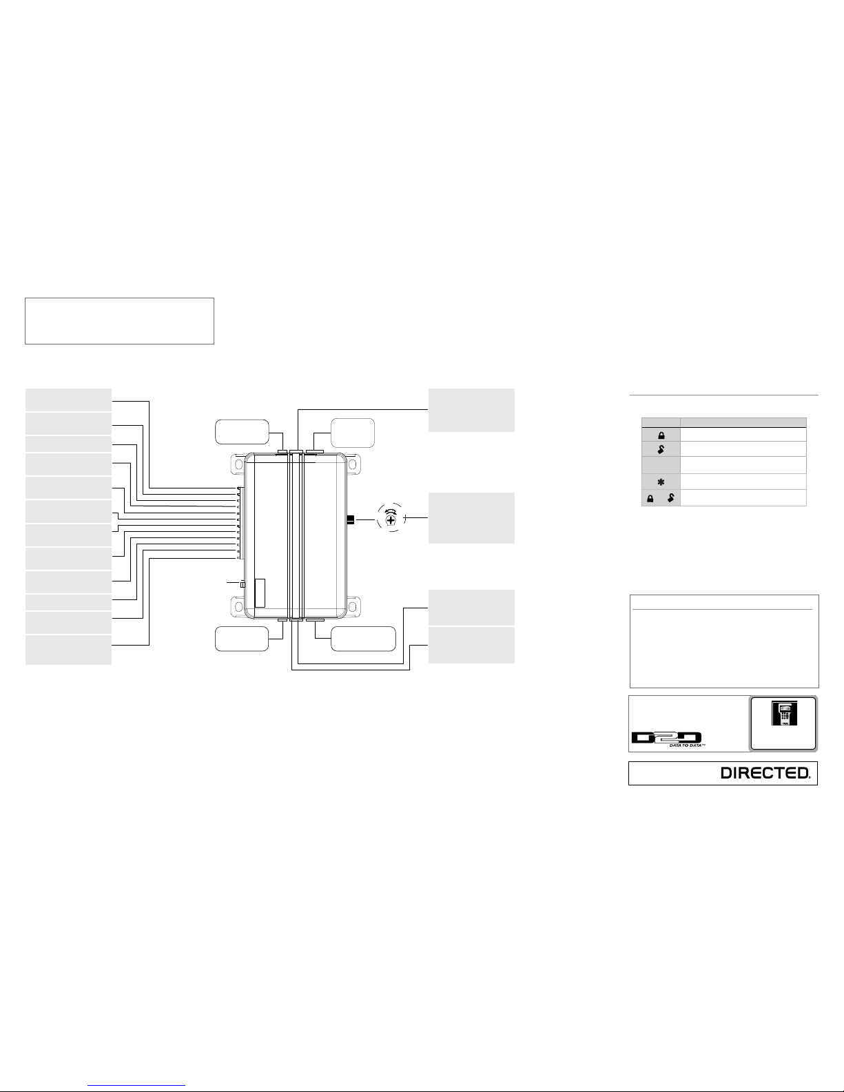
Sensor adjustment
detail
Optional Sensor Port
White 4 Pin Plug
LED Port
White 2 Pin Plug
Vatet Switch Port
Blue 2 Pin Plug
Antenna
Port
(-)
(+)
Red/White (-) 200mA Chan 2 Output
Green (-) Lock, (+) Unlock Output
Blue (-) Unlock, (+) Lock Output
Light Flash Jumper
Red (+) 12V Constant Power
Brown (+) Siren Output
Yellow (+) Ignition Input
Black (-) Chassis Ground
Violet (+) Door Trigger Input
Blue (-) Instant Trigger Input
Green (-) Door Trigger Input
Black/White (-) Domelight Sprvsn Output
White/Blue (-) 200mA Chan 3 Output
White (+/-) Light Flash Output
Orange (-) 500mA GWA Output
Wiring Connections
Channel 2 Output: Connect to the
vehicle negative (-) trunk release relay or other low current device
12V Constant Power: Remove the
inline fuse before connecting to a
wire that has (+) 12V at all times
Siren Output: Connect to the (+)
wire on the siren
Ignition Input: Connect to a wire
that has (+) 12V while the key is in
the run and crank positions
Chassis Ground: Connect to a
scraped (bare) metal surface in the
driver kick
Door Trigger Input: Connect to a
wrie that goes to (+) 12V when any
door is opened
Instant Trigger Input: Connect to a
wire that goes to ground (-) when
the hood or trunk are opened
Door Trigger Input: Connect to a
wire that goes to (-) ground when
any door is opened
Domelight Supervision Output:
Connect to a (-) wire that will turn on
the domelight
Channel 3 Output: Connect to an
auxiliary relay or low current device
Light Flash Output: Connect to the
vehicle parking light wire. This wire
is programmable + or -
Ground When Armed Output:
Connect to a starter interrupt relay
or other accessory that requires a
GWA
Important: NEVER connect 200mA low current outputs
directly to a motor or high current device WITHOUT a
relay,
Programming Port: The 998T Bitwriter can be connected to this port
for programming feature options.
SmartStart can be connected to this
port to operate the system by Smartphone.
Adjusting the shock sensor pot:
1. Securely mount the CPU (in a
safe location) before adjusting
2. Turn the sensor adjustment
clockwise to increase sensitivity, turn counterclockwise to
decrease sensitivity
(-) Lock, (+) Unlock Output: Connect to a wire that pulses ground to
activate the vehicle lock relay or to
a wire that pulses (+) 12V to activate the vehicle unlock relay
(-) Unlock, (+) Lock Output: Connect to a wire that pulses (-) ground
to activate the vehicle unlock relay
or to a wire that pulses (+) 12V to
activate the vehicle lock relay
Bitwriters with a date code of 6a or older require an IC
upgrade (p/n 998M). Some bitwriters with a date code
of 6B do not require the IC upgrade, refer to tech tip #
1112 for more information.
The Bitwriter® (p/n 998U)
requires chip version 2.4 or
newer to program this unit.
Remote control configuration
4- button remote control configuration
Feature Description
Arm: Lock the doors and arm the vehicle
Disarm: Unlock the doors and disarm the vehicle
AUX
Channel 2/Silent Mode: Activate Silent Mode and
Auxiliary functions
AUX
Panic
and
Channel 3: Press together to control an Auxiliary output
More information and full Installation Guide can be found online at:
www.directechs.com
Page 2
© 2012 Directed. All rights Reserved. 2
QRN3305 2012-09
Programming System Features
The System Features Learn Routine dictates how the unit operates. It is possible to access and change most of the feature settings using the Valet switch/Control button.*
*Depending on which model is installed, the system uses either an external Valet
switch and an external Status LED or a Control Center with an onboard Control button (Valet Switch) and Status LED.
1. Open a door.
2. Tur n the ignition on, then off.
3. Select a Menu. Press and hold the Valet switch/Control button. The number
of siren chirps indicates the menu number. 1 chirp indicates menu 1, 2 chirps
- menu 2.
4. When the desired menu chirps are heard, release the Valet switch/Control
button.
5. Select a Feature. Press and release the Valet switch/Control button the
number of times corresponding to the feature you wish to change. Then press
and hold one more time to select the features.
6. Program the Feature. While holding the Valet switch/Control button, you can
program the feature using the remote control.
To change the desired options press;
= one chirp setting, while
= two
chirps setting.
Once a feature is programmed:
• Other features can be programmed within the same menu
• Another menu can be selected
• The learn routine can be exited if programming is complete
To access another feature in the same menu:
1. Press and release the Valet switch/Control button the number of times necessary to advance from the feature you just programmed to the next one you
want to program.
2. Then press the Valet switch/Control button once more and hold it.
To select another menu:
1. Press and hold the Valet switch/Control button.
2. After 3 seconds, the unit advances to the next menu and the siren chirps, indicating which menu has been accessed.
The learn routine exits if any of the following occurs:
• The open door is closed
• The ignition is turned On
• There is no activity for 20 seconds
• The Valet switch/Control button is pressed too many times
Bitwriter - Only Options
If programming with the Bitwriter®, the learn routine can be locked or unlocked. If the learn routine has previously been locked, it must be unlocked
with Bitwriter® - this cannot be done manually with the Control button.
The Bitwriter® gives you access to a wider range of system options. These
features and the adjustments that may be programmed are described in the table
below. Default settings are in bold type.
Menu
Item
Feature Default Option 2
1 Ignition Controlled
Lock
Ignition Controlled
Lock ON
Ignition Controlled
Lock OFF
2 Ignition Controlled
Unlock
Ignition Controlled
Unlock ON
Ignition Controlled
Unlock OFF
3 Siren Duration
30 second siren
duration
1-180 seconds (in 1
second increments)
Feature Menus
Default factory settings are in bold type.
Menu 1: Basic Features
Feature # 1- chirp setting 2- chirp setting
1-1
Active arming
Passive arming
1-2
Chirps ON
Chirps OFF
1-3
Ignition controlled door locks
ON
Ignition controlled door locks OFF
1-4
Active locking only
Passive locking
1-5
Panic w/ignition ON
No Panic w/ignition ON
1-6
0.8 second door lock pulses
3.5 second door lock pulses
1-7
Forced passive arming ON
Forced passive arming OFF
1-8 Automatic Engine Disable ON
Automatic Engine Disable OFF
1-9
Armed When Driving (AWD)
Vehicle Recovery System (VRS)
1-10
Code Hopping™ ON
Code Hopping OFF
Menu 2: Advanced Features
Feature # 1- chirp setting 2- chirp setting
2-1
Siren
Horn Honk
2-2
30 second siren duration
60 second siren duration
2-3
NPC®
ON
NPC OFF
2-4
Progressive door trigger
Instant door trigger
2-5
Valet switch/Control button
input: 1 pulse
Valet switch/Control button input
2-5 pulses
2-6
Door trigger error chirp ON Door trigger error chirp
OFF
2-7
Ignition controlled domelight
ON
Ignition controlled domelight OFF
2-8
Single unlock pulse
Double unlock pulse
2-9
Single lock pulse
Double lock pulse
2-10
Channel 3: Validity
Channel 3: latched/
latched reset with ignition/
30- second timed/
second unlock output*
2-11 Comfort Closure (ON, 20 sec)
Comfort Closure (OFF)
*Second unlock available only if feature 2-8 is programmed to single
pulse.
Remote control learn routine
The system comes with two remote controls that have been taught to the control
module. The control module can store up to four different remote control codes in
memory. The button configurations can be changed on the remote control, follow
the procedure below and use the table to configure it for an associated function.
If the system was previously programmed using the 998T Bitwriter, the learn routine
may be locked. If the siren generates one long chirp when attempting to program
the unit, the learn routine is locked and must be unlocked using the 998T Bitwriter
before proceeding.
1. Open a door. The 12 pin harness GREEN wire or the 12 pin harness VIOLET
wire must be connected.
2. Turn the ignition on. The 12 pin harness YELLOW wire must be connected.
3. Select a channel. Press and release the Valet switch/Control button the number
of times necessary to access the channel you want, and then press and hold
the Valet switch/Control button once more. The siren chirps and the LED blinks
the number of times corresponding to the channel accessed.
4. While holding the Valet switch/Control button, press the button on the remote
control you want to assign to the selected channel. The unit chirps indicating
successful programming.
Note: It is not possible to teach a remote control button to the system more
than once.
Note: When programming channels 1- 6, a button must be taught to the unit in
Channel 1 or Channel 5 before programming remaining channels.
Channels 2, 5, 6: Use Channels 2, 5, and 6 to assign the arm, disarm and panic
functions to buttons on the remote control. Teaching a button to Channel 5 or Channel 1 erases some memory information, and auxiliary functions may have to be
reprogrammed.
Channel/ Function
Channel # Function
1 Arm/Disarm
2 Panic Only
3 Silent mode, Remote Valet,
Trunk Release
4 Remote starter or other accessories
5 Arm Only
6 Disarm Only
7 Auto learn standard 4- button configuration*
8 Auto learn 3- button configuration*
9 Delete all transmitters**
* For auto learn configurations, see Remote control (transmitter) configurations
section of this guide.
** The delete all transmitters option also resets the programmed settings to their
default factory state.
The learn routine exits if any of the following occurs:
• The open door is closed
• The ignition is turned off
• There is no activity for 15 seconds
• The Valet switch/Control button is pressed too many times
Long Term Event History
The system stores the last two full triggers in memory. These are not erasable. Each
time the unit sees a full trigger, the older of the two triggers in memory is replaced by
the new trigger. To access long term event history:
1. With the ignition Off, press and hold the Valet switch/Control button.
2. Tur n the ignition On.
3. Release the Valet switch/Control button.
4. Within 5 seconds, press and release the Valet switch/Control button. The
status LED flashes in groups indicating the last two zones that triggered the unit
for 1 minute or until the ignition is turned off. Refer to table of zones.
Note: The Warn Away triggers are not stored to memory and is not reported.
Table of Zones
A zone is represented by the number of status LED flashes used by the
system to identify a particular type of input.
Zone Description Input Description
1 Optional trigger input 12 pin harness Blue wire
2 Instant trigger: a heavier impact
detected by the shock sensor
Onboard Shock Sensor.
3 Door switch trigger 12 pin harness Green or Violet wire
4 Instant trigger: For optional sensors Optional Sensor Port
5 Ignition trigger 12 pin harness Yellow wire
 Loading...