

Directechs DB3 Installation Manual
Designed by Installers for Installers
INSTALLATION GUIDE
DB3
2012 Hyundai Accent. 403.HKHT1 3.17
© 2018 Directed, Vista CA
This product is intended for installation by a professional installer only! Attempts to install this
product by a person other than a trained professional may result in severe damage to a vehicle’s
electrical system and components.

Contents
Introduction 4
Vehicle function compatibilities 4
Pre-installation and application warnings 5
Wiring diagram 5
Locating components in the vehicle 7
Vehicle connections 8
Connecting the module 11
Module programming 12
Programming WITH FT CAN connection & WITHOUT Transponder Immobilizer: 13
Programming WITHOUT FT CAN connection & WITH Transponder Immobilizer: 12
Programming WITH FT CAN connection & WITH Transponder Immobilizer: 12
LED diagnostics and troubleshooting 14
Soft reset 16
Hard reset 16
Feature programming 17
Feature and option list 18
Limited one year consumer warranty 19
Quick reference guide 20

Warning! Safety first
The following safety warnings must be observed at all times:
• Due to the complexity of this system, installation of this product must only be performed by an authorized Directed dealer.
• When properly installed, this system can start the vehicle via a command signal from the remote control. Therefore, never
operate the system in an area that does not have adequate ventilation.
The following precautions are the sole responsibility of the user; however, authorized Directed dealers should:
• Never use a test light or logic probe when installing this unit. Always use a multimeter.
• Never operate the system in an enclosed or partially enclosed area without ventilation (such as a garage).
• When parking in an enclosed or partially enclosed area or when having the vehicle serviced, the remote start system must
be disabled using the installed toggle switch. It is the user’s sole responsibility to properly handle and keep out of reach from
children all remote controls to assure that the system does not unintentionally remote start the vehicle.
• USER MUST INSTALL A CARBON MONOXIDE DETECTOR IN OR ABOUT THE LIVING AREA ADJACENT TO THE VEHICLE.
ALL DOORS LEADING FROM ADJACENT LIVING AREAS TO THE ENCLOSED OR PARTIALLY ENCLOSED VEHICLE
STORAGE AREA MUST REMAIN CLOSED AT ALL TIMES.
Use of this product in a manner contrary to its intended mode of operation may result in property damage, personal injury, or
death. Except when performing the Safety Check outlined in this installation guide, (1) Never remotely start the vehicle with
the vehicle in gear, and (2) Never remotely start the vehicle with the keys in the ignition. The user is responsible for having the
neutral safety feature of the vehicle periodically checked, wherein the vehicle must not remotely start while the car is in gear.
This testing should be performed by an authorized Directed dealer in accordance with the Safety Check outlined in this product
installation guide. If the vehicle starts in gear, cease remote start operation immediately and consult with the user to fix the problem
immediately.
OPERATION OF THE REMOTE START MODULE IF THE VEHICLE STARTS IN GEAR IS CONTRARY TO ITS INTENDED MODE OF
OPERATION. OPERATING THE REMOTE START SYSTEM UNDER THESE CONDITIONS MAY RESULT IN PROPERTY DAMAGE
OR PERSONAL INJURY. IMMEDIATELY CEASE THE USE OF THE UNIT AND REPAIR OR DISCONNECT THE INSTALLED REMOTE
START MODULE. DIRECTED WILL NOT BE HELD RESPONSIBLE OR PAY FOR INSTALLATION OR REINSTALLATION COSTS.
Remote starters for manual transmission pose significant risks if not properly installed and operated. When testing to ensure the
installation is working properly, only remote start the vehicle in neutral gear, on a flat surface and with a functional, fully engaged
parking brake. Do not allow anyone to stand in front of or behind the vehicle.
This product should not be installed in any convertible vehicles, soft or hard top with a manual transmission. Installation in such
vehicles may pose certain risk.
403.HKHT1 3.17 2012 Hyundai Accent
3
© 2018-08-13 Directed. All rights reserved.
Introduction
DB3 is an all-in-one door lock and override module.
Warning!
This module can only be flashed and configured using DirectLink at www.directechs.com or using the Directechs
Mobile application for smartphones. Refer to “Connecting the module” for more information.
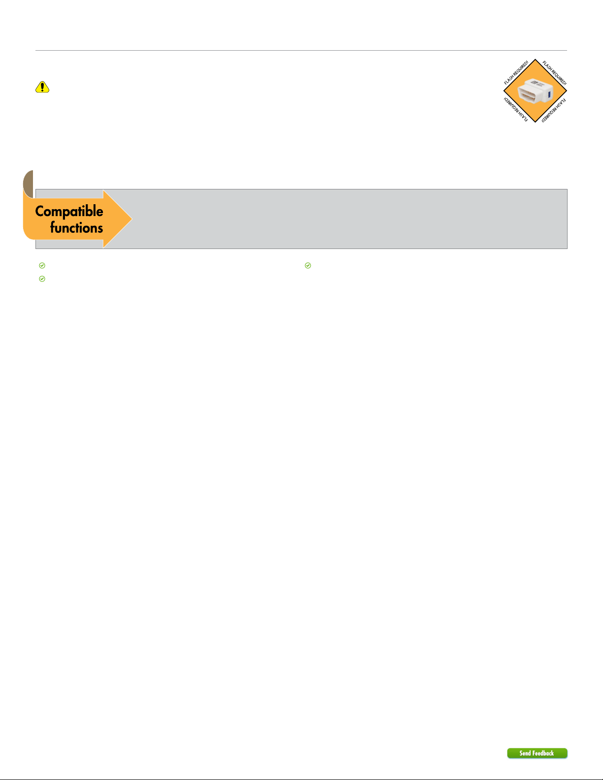
Vehicle function compatibilities
This section lists all the functions compatible with this vehicle for the installation illustrated in this guide.
Immobilizer Bypass-Data No Key Req'd
Tach / RPM Output
Brake Status (foot brake)
403.HKHT1 3.17 2012 Hyundai Accent
4
© 2018-08-13 Directed. All rights reserved.
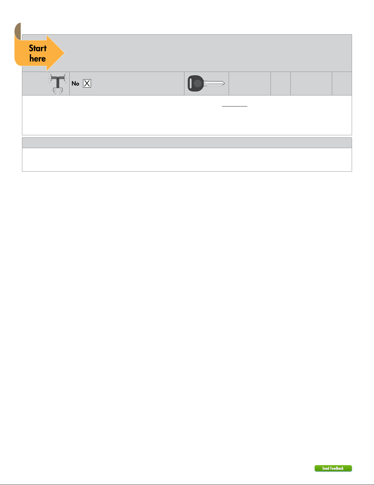
Pre-installation and application warnings
Firmware notes: This section highlights important information for this specific firmware and will assist in
pricing accordingly, as well as bringing awareness to any operational or vehicle limitations.
T-Harness
compatible
Keys required for
programming
Keys required for
1
operation
Important! If your vehicle is NOT equipped with transponder immobilizer AND also does NOT use CAN connections,
please flash your module with analog firmware.
All connectors are displayed from the wire side (unless specified otherwise).
Refer to the "Vehicle connections" following the installation diagram.
General notes: This section highlights important information for this specific firmware.
[1] Tach wire is an optional connection required on some remote starters, which do not support a tach signal in D2D.
[2] EMS COM connections only needed if vehicle has a transponder immobilizer.
0
403.HKHT1 3.17 2012 Hyundai Accent
5
© 2018-08-13 Directed. All rights reserved.
1412
10
42
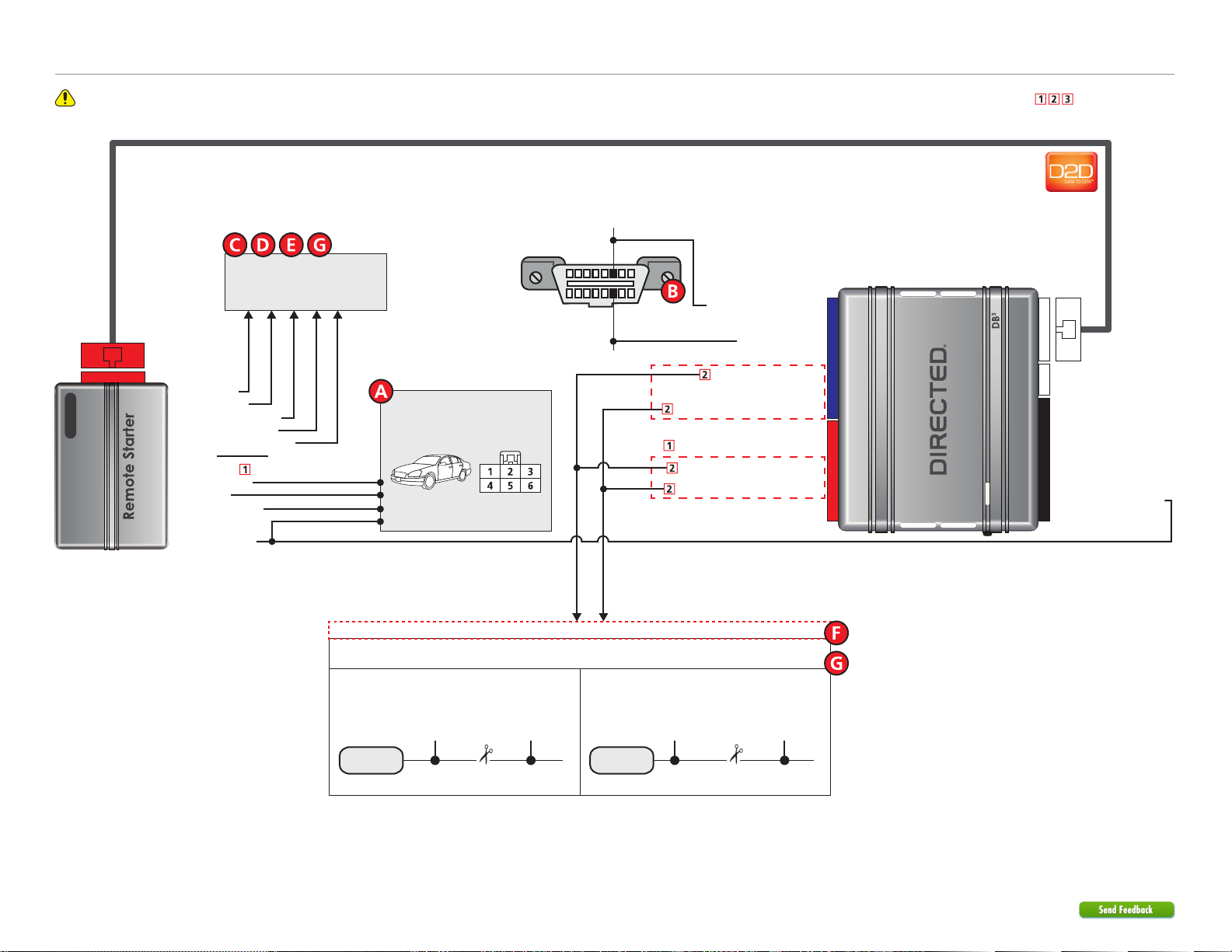
Wiring diagram
Refer to "Pre-installation and application warnings" for important information, such as the description of each special note referenced in the diagram ( ).
C-CAN High:
pin 6
XKD2D65
D2D Port
Refer to Vehicle connections
section for corresponding
connector, pin and wire color
of your vehicle.
(-) Lock Output
(-) Unlock Output
(-) Parking Lights Output
(-) Trunk Release Output
(-) Driver Door Trigger Input
(-) Ground (-) Ground
(AC) Tach Input
(+) Starter Output
(+) 12V Input
(+) Accessory Output
(+) Ignition Output
Diagnostic Connector
OBDII
(wire side view)
Ignition, Accessory, Starter
1 8
C-CAN Low:
pin 14
169
HS CAN High: Tan/Black: 3
HS CAN Low: Tan : 4
EMS COM Data: Yellow: 8
EMS COM Data: Orange/Yellow: 9
& (+) 12V wires at ignition
switch, 6-pin connector
Refer to the Vehicle
connections section.
(AC) Tach Output: Violet/White: 5
EMS COM Data: Yellow/Black: 10
EMS COM Data: Orange/Black: 11
EMS COM connections only needed if vehicle has transponder/immobilizer.
EMS COM Connection Type
See the Vehicle connections section for the connector, pin and wire color for your vehicle.
Connection Type A
Yellow +
Yellow/Black wires
from Interface
Connector
Orange/Yellow +
Orange/Black wires
from Interface
Cut
Connection Type B
Orange/Yellow +
Orange/Black wires
from Interface
Connector
Yellow/Black wires
Cut
9: Pink: (+) Ignition Input
Yellow +
from Interface
403.HKHT1 3.17 2012 Hyundai Accent
6
© 2018-08-13 Directed. All rights reserved.
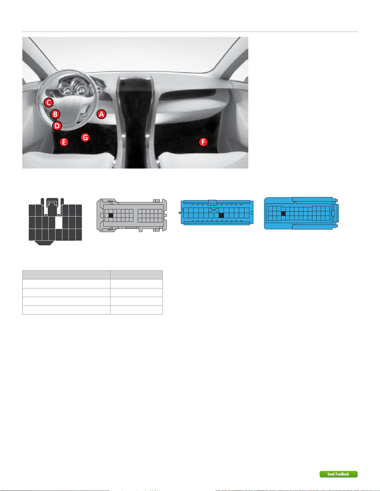
Locating components in the vehicle
Locating components in the vehicle
All adapters are displayed from the wire side (unless specified otherwise).
1
- EM01, Black 21-pin conn.
11
EMS COM connection type
Vehicle Connection type
Hyundai Accent 2012-2016 Type B
Hyundai Elantra Touring 2009-2012 Type B
Hyundai Santa Fe 2008-2012 Type A
Kia Rondo 2008-2012 Type A
2 - EM11, Gray 39-pin conn.
15
3 - MC211, Blue 24-pin conn.
19
4 - EM11, Blue 42-pin conn.
18
403.HKHT1 3.17 2012 Hyundai Accent
7
© 2018-08-13 Directed. All rights reserved.
 Loading...