

DirectConnect DCRACK38U, 19929, DCRACK29U, 19930, 19931 User Manual
...
HHeellppiinngg yyoouu aacchhiieevvee yyoouurr iinnssttaallllaattiioonn nneeeeddss!!
DDiirreeccttCCoonnnneecct
t ® is one of the largest manufacturers of products
specifically for the custom installation of audio, video, security,
telecom and data networking industry.
OOuurr eexxtteennssiivvee pprroodduucctt lliinne
e offers items in the categories of bulk
wire and cable, connectors, installation hardware, interconnect
cables, distribution panels, a/v transceivers, cameras, media
servers, baluns, mounts, tools and wall plates—virtually everything
a custom installer needs!
SSiinnccee 11999966,, DDiirreeccttCCoonnnneecct
t
®
®
has offered unique products that
provide solutions to everyday installation headaches.
Houston, Texas 77027
Phone 800.531.3224
Would it make your day to know that someone is waiting to hear from you?
We are. Your DirectConnect® representative is ready to take your call.
Or if you prefer, visit us online at …
http://www.directconnecthome.com
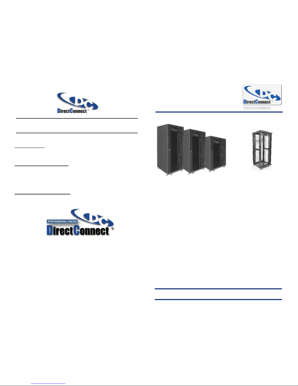
PPrrooffeessssiioonnaall SSeerriieess RRaacckks
s
DDCCRRAACCKK2299U
U .19929
DDCCRRAACCKK3388U
U .19930
DDCCRRAACCKK4422U
U .19931
CCoommpplleettee RRaacckk wwiitthh ccaasstteerrss,, ppoowweerr ssttrriipp,
, USER MANUAL
tthheerrmmaall ccoonnttrrooll aanndd dduuaall ffaanns
s
PROFESSIONAL SERIES RACKS 29U, 38U, and 42U
DirectConnect® offers solutions for custom installers and custom system integrators with a full
line of multi-use Professional Racks that deliver extraordinary capabilities in construction and
performance: elegant yet secure lockable, solid steel construction; thermal system; power
control; and a robust caster system.
These space saving and sturdy racks offer locking custom-designed, see-through, tempered
front and vented rear doors and removable sides, which provide quick access to all your
Audio/Visual, Servers, and Network equipment. The rack’s top-mounted, thermal-controlled
dual fans and ventilation construction efficiently remove heat produced from your enclosed
equipment. The internal numbered mounting rails are depth-adjustable to fit virtually any piece of
19” equipment. And, in addition to all the included equipment that are options on most other racks,
DirectConnect® also has a full line-up of optional accessories like rack blanks (1U-4U), extra A/C
power distribution strips, standard and/or vented fixed shelving (1U-3U), and sliding (pull out) shelving.
EASY INSTALLATION: Quick and easy assembly - Four easy steps
EASY ACCESS: Removable side s and reversible front and rear doors
POWER ACCESS: 1U 6 outlet Power Distribution Strip with protected on/off switch
UNIVERSAL MOUNTING: Numbered solid steel adjustable mounting rails
COOLING: 1U Digital Thermal Controller and top loaded dual 5” Cooling Fans
VENTILATION: Custom tempered glass door and vented rear door
CABLE MANAGEMENT: Removable cable plates in rack’s top & base, plus space between
rails & door for 2” x 2” PVC cable management molding
SAFETY: Locking vented tempered glass front & vented rear doors, adjustable feet on all
four corners and heavy duty locking removable caster system
(six screws)
REV07/22/11
IMPORTANT: If you do not understand correct installation instructions,
please consult your installation specialist.
8 / 8
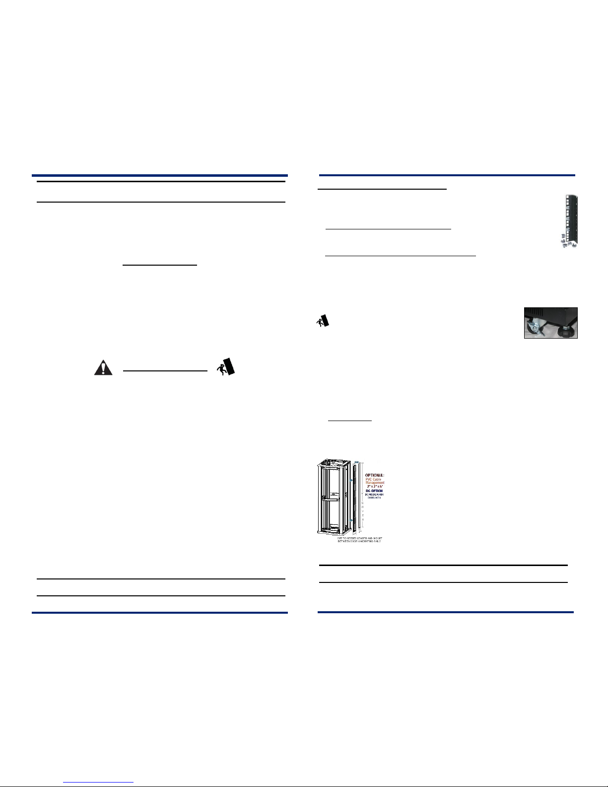
Fig. 7a
Fig. 7
TThhaannkk yyoouu ffoorr cchhoooossiinngg DDiirreeccttCCoonnnneecct
t
®
®
PPrroodduuccttss
DDeeaarr CCuussttoommeerr
Thank you for purchasing this DirectConnect® product. For optimum performance
and safety, please read these instructions carefully before assembling, operating, or
adjusting this product. Please keep this manual for future reference.
Table of Content
1.0 Hardware List ……………………….……… 3
2.0 Features ……………………………………… 4
3.0 Package Contents…………………………… 4
4.0 Installation Guide ………………………….… 5
4.1 Un-packaging 2 of 3 & Installation Guide…. 5
4.2 Un-packaging 1 of 3 & Installation Guide…. 5
4.3 Un-packaging 3 of 3 & Installation Guide..... 6
4.4 Installing the Doors and Panels …………..… 6
5.0 Operation and Adjustment…………………... 7
SAFETY WARNING:
1. These DirectConnect® Professional Series Racks are intended for use only
within the maximum weights indicated. See apparatus instructions. Use with
products heavier than the maximum weights indicated may result in instability,
causing possible injury.
2. Do not climb on, rock, shake, stand on, or tilt your Professional Series Racks.
3. Someone with good mechanical aptitude, who has experience with basic building
construction, & who fully understands this manual, should install this product.
4. Safety gear and proper tools must be used. A minimum of two people could be
required for this installation. Failure to use safety gear can result in property
damage, serious injury or death.
5. This product contains small items that could be a choking hazard if swallowed.
Keep these items away from young children.
6. Never exceed the Maximum Load Capacity.
7. Do to the height and weights of the Professional Series Racks do not move by
yourself assistance is required. Always use an assistant or mechanical lifting
equipment to safely lift and position equipment.
8. Tighten screws firmly, but do not over-tighten. Over-tightening can damage the
items, greatly reducing their holding power.
IMPORTANT: If you do not understand correct installation instructions,
please consult your regular installation specialist
*DirectConnect® is a registered trademark.
5.0 OPERATION AND ADJUSTMENT
1) The DirectConnect® Professional Series mounting rails (A & B) 10-32 pre - threaded
holes and the (J & K) 10-32 square knockout holes (as shown in Figure 7) are labeled in
EIA standard rack space increments allowing for easy equipment alignment.
a) Using threaded mounting rails (A & B) for front - Select the location that the equipment
is to be mounted and screw down the equipment with 10-32 bolts (H). The mounting rails
(A & B) have pre-threaded 10-32 holes just screw equipment directly into desired position.
b) Using square knockout mounting rails (J & K) for front - Select the location that the
equipment is to be mounted and insert the supplied 10-32 snap nuts (I) by pressing on either
side of the nut, then insert the clamp side into the square hole, and release into the mounting
rails (J & K) where the equipment is to be mounted. To completed screw down the equipment
with 10-32 bolts and 10-32 snap nuts (H & I) into desired position
c) If the equipment has mounting with hooks, j ust hook the bracket into position for any
equipment that has mounting brackets with hooks
2) The DirectConnect
®
Professional Series Racks are equipped
with locking heavy duty casters (D) to move the rack easily. There
are four (4) adjustable locking feet (C) on the base of the rack, use a
wrench to adjust the feet until the legs are lowered enough that the wheels are slightly off the
ground and lock with nut to base. Also they ensure that the rack does not tip forward when a
heavy drawer is pulled out.
(
CAUTION - feet may damage flooring if rack is moved when loaded with equipment)
3) Determine the type of optional shelves - Fixed or Sliding
a) Fixed Shelves - secured to the mounting rails (A & B or J & K) using supplied 10-32 bolts (H). Short
shelves use 10-32 bolts (H) to attach into place to the front mounting rails (A & B or J & K) of the rack.
Deeper shelves determine the desired height that you want to install the shelf at, and then fasten
the shelf with the provided 10-32 bolts (H) to the front of the mounting rails (A & B or J & K).
b) Sliding Shelves - Determine the desired height to install the shelf then line up with the
holes on the mounting rails (A & B or J & K) use 10-32 bolts (H) to fasten sliding shelf’s guides.
CAUTION:
To avoid damage to your components due to overheating, ensure that there is adequate space between each unit
for proper airflow. It is important to maintain an operating tem perature inside of the rack that does not exceed 104°F (40°C).
4) Attach the 1U Power Strip (6) at desired location using supplied 10-32 bolts (H) or 10-32
bolts and snap nuts ( H & I). Plug power strip’s A/C cord into A/C outlet.
5) Attach the 1U Thermal Control unit (7) at desired location using
supplied 10-32 bolts (H) or 10-32 bolts and snap nuts ( H & I). Connect
the thermal power cord (8). Plug A/C cord from dual fans in Fan Top
Assembly (4). Locate the thermal control unit’s thermal sensor at
desired location. See Thermal
6) The DirectConnect® Professional Series Racks are designed to
accommodate other optional accessories like 2” x 2” PVC cable
management molding between the door frames (1 & 2) and the racks
mounting rails (A & B or J & K) as shown in Figure 7a.
IMPORTANT: Do not force the bolt into the hole, which may damage equipment and injure of person. Do
not use electric drill to fasten any bolts.
TThhaannkk yyoouu ffoorr cchhoooossiinngg DDiirreeccttCCoonnnneecct
t
®
®
PPrroodduuccttss
IMPORTANT: If you do not understand correct installation instructions, please consult your installation specialist
* This DirectConnect® is a registered trademark.
2 / 8
7 / 8
 Loading...