

Direct Color Systems DJ1024UVMVP Read Me First
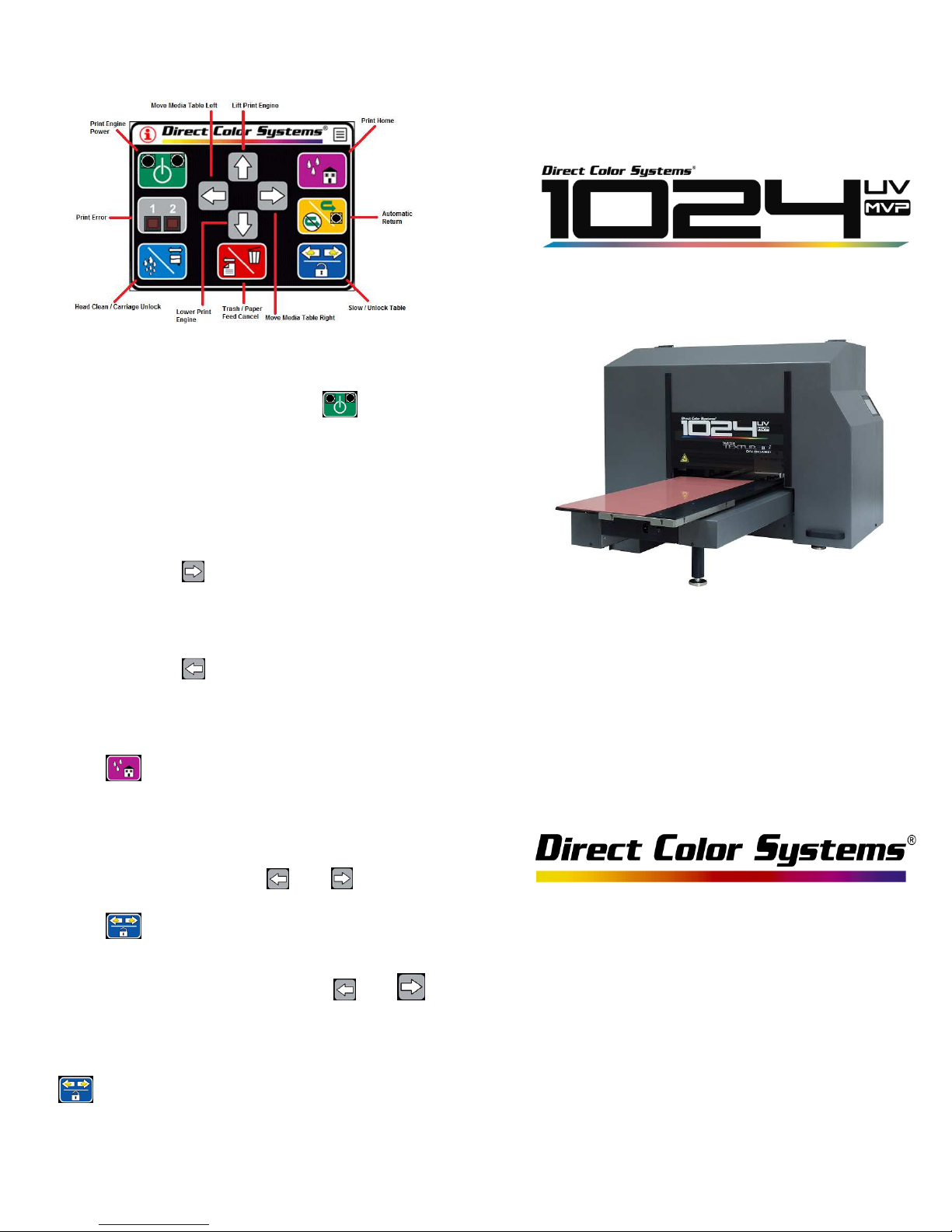
LCD Control Panel
Test Printer Functionality
Turn on print engine by pressing . Amber
light will turn off. When green light is solid,
print engine is powered on and ready.
With print engine at max height, test basic
functions of printer movement
Read Me First
Press and hold to move media table all
the way to the right. Media table will stop
once it has reached the right limit of printer.
Press and hold to move media table all
the way to the left. Media table will stop
once it has reached the left limit of printer.
Press to bring the media table to the
Print Home position. Media table will travel
to the right limit and advance several inches
to the left, and lock in the print home
position deactivating the and buttons.
Press to unlock the media table from
the print home position. Media table will
travel to the right limit of printer and
will be active again.
Test slow function by pressing and holding
to view the slow speed screen.
For further in st ru ctions, p le ase refer to th e
Getting Starte d Guide.
The full DJ1024UVMVP User's Guide has
been provided in digital format on the
orange USB security device (dongle).
The guide can also be found on our ftp site:
ftp://ftp.directcolorsystems.com/.
Login: dcs Password: dcsftp
99 Hammer Mill Road
Rocky Hill, CT 06067
+1 860-829-2244
info@directcolorsy stems.com
www.directcolorsystems.com
Rev . 1.2
030314
Out of the box
Removing Shipping Brackets
Remove the printer from its packing. Do not
dispose of the box. The printer weighs 231
lbs (104kg) so at least two people are needed
to lift the printer. Place it on a flat, stable
surface with a minimum of 12" (305mm) of
space on all sides. Locate the table so that
you have access to all sides of the printer.
Ensure that all leveling feet are fully on the
surface of the table. The printer should be
determined to be level in all directions.
DO NOT PLUG IN THE PRINTER YET
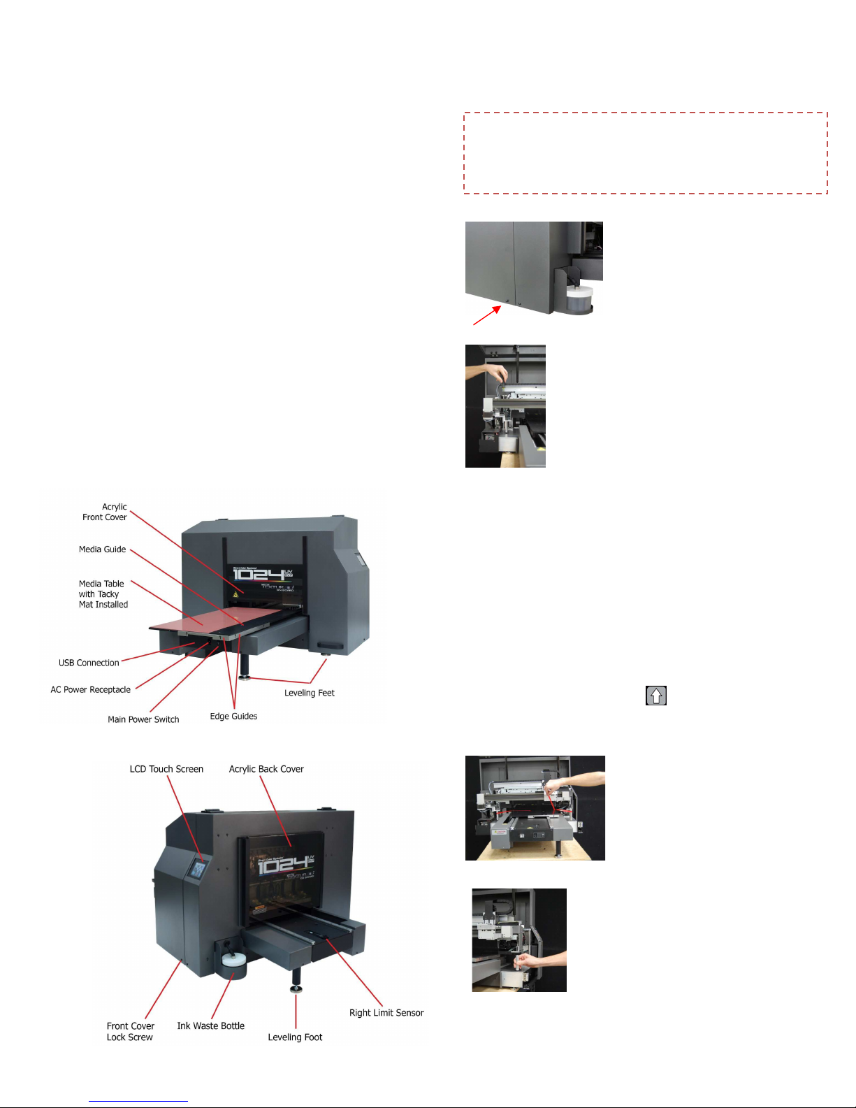
Getting Familiar with the
1024UVMVP
DO NOT PLUG IN THE PRINTER YET
Warning: Wh en printer is in operation, all covers
should b e installed and closed with the front cover
lock screws installed and secured. Th e cover should
only be opened by trained DCS personn el only
Using the provided T15
Torx tool, remove the two
front cover lock screws.
Open the front cover using
both handles.
Remove the bolts securing print
engine to shipping brackets with
the provided T-handle tool. Do not
dispose of these bolts.
Remove the warning label over the AC power
receptacle. Plug in main power cord and flip
main power switch to ON.
The Ink Level screen will appear on the LCD
Touch Screen. Silence the alarm by hitting any of
the LOW ink lights.
Select the Home icon from the top left of the LCD
screen. Press and hold to raise the print
engine to its maximum height.
Remove the tape from the
media table and shipping
brackets.
Remove the two brackets by
unscrewing them from the main
channel. You cannot simply pull
these brackets out. Do not
dispose of these brackets.
Close and secure front cover.
 Loading...