

DirectBikes -DB50QT-11 User Manual
Manual-DB50QT-11

1
Dear Customer:
Thank you for purchasing the Direct Bikes DB50QT-11 scooter.
The Direct Bikes DB50QT-11 scooter is manufactured using some of the
most advanced production techniques in the world. The scooter features high
performance, economic fuel consumption and low noise levels. This manual
provides detailed information about the correct operation, maintenance and
adjustment of your DB50QT-11 scooter. Please read this manual carefully to
ensure safety and maximum ease of use.

2
Important Notice:
• Driver and passenger
This vehicle is designed to carry only one driver and one passenger. The
driver is required to have the appropriate licence for these requirements.
Do not exceed the rated load capacity specied on the specication label.
• Road condition
This vehicle is designed to travel on at roads. Do not ride this vehicle in
freezing or hazardous conditions.
• Modications
This vehicle should not be modied.
CAUTION:
Personal injury or mechanical damage may result if you fail to operate
as instructed in the manual.
3
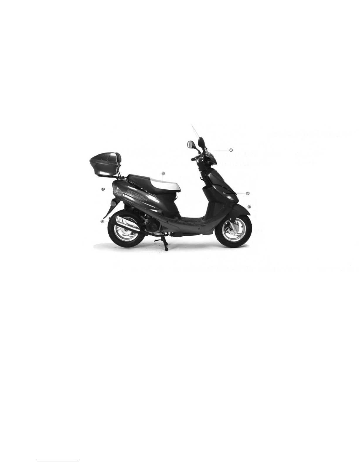
Location of Component parts
(1) Back-view mirror (2) Headlight (3) Front turn signal light
(4) Mufer (5) Taillight (6) Seat
4
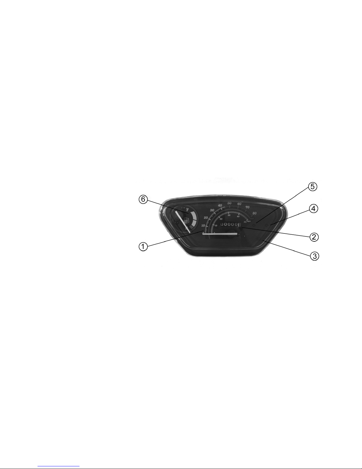
Meter Panel and Indicators
All the controls for the indicators and warning lights are located on the meter
panel.
(1) Speedometer
(2) Mileometer
(3) High beam indicator
(4) Turn right signal light
(5) Turn left signal light
(6) Fuel meter
Fuel gauge
The fuel gauge indicates the approximate amount of fuel remaining in the fuel
tank. When the needle pointer stays in the F(full) position, it means the total
capacity of the fuel tank is now 6.0 litres (including reserve fuel). When the
needle pointer approaches the rst dot on the red mark, it means that the fuel
tank must be relled immediately.

5
Identication
The VIN or chassis number is located on the frame of the scooter and is
either under the seat or under the clip in cover in the front of the foot well.
The engine number is located on the left side on the bottom of engine.
NOTE:
You should regard this manual as a permanent component part of your
vehicle, it is essential for the continued operation and safety of your
scooter to perform periodic servicing by an approved dealer. This is
required under your warranty.
6
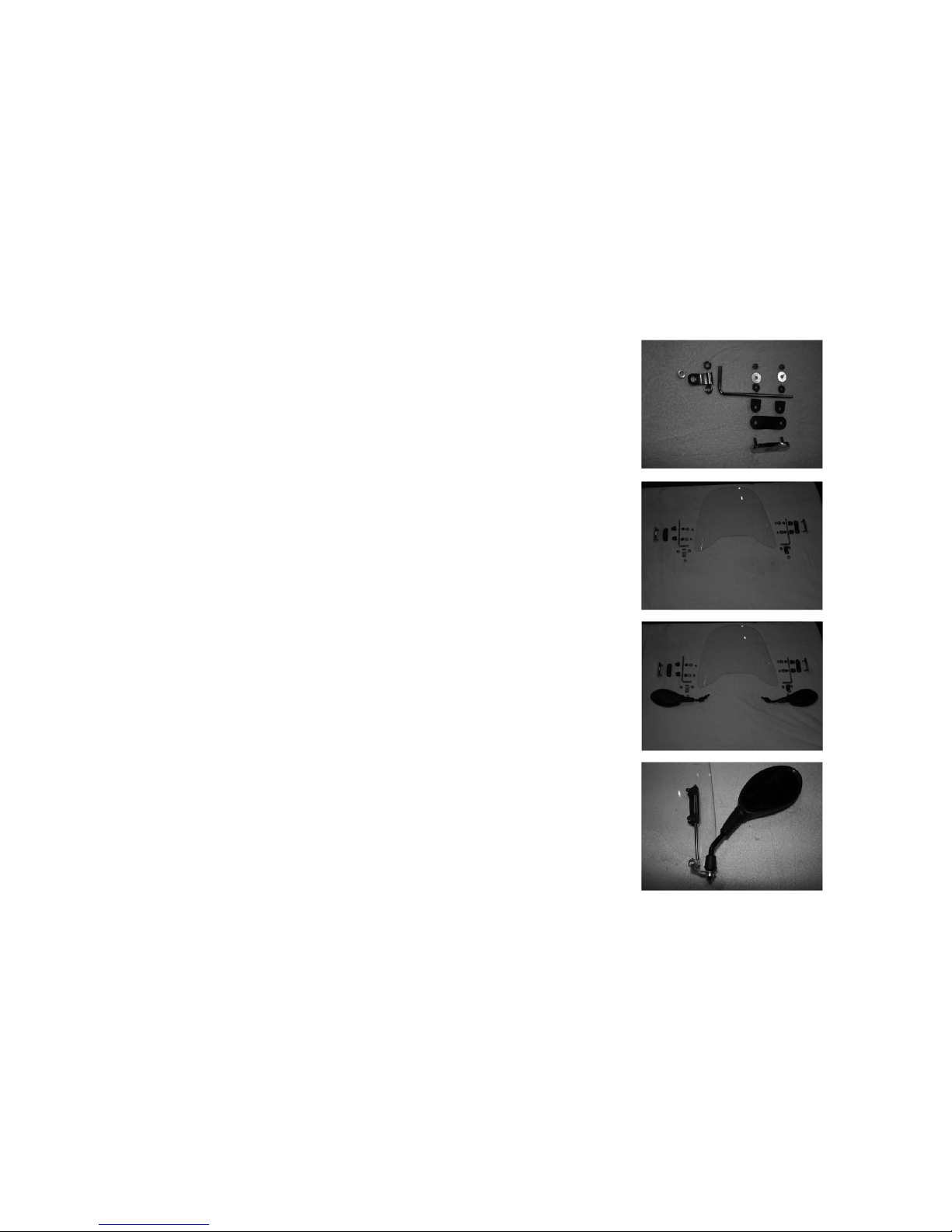
Fitting the accessories
Screen
The screen mounting kit utilises the mirror mounts to
x it to the scooter. Start by sliding 2 of the plastic
lugs over the L shaped chrome bars. The bars are
handed left and right. Next screw 1 nut onto the short
threaded part all the way, nger tight. Put the mirror
mount on so that the at part faces down. Put the
other nut on nger tight. Next place the mirror through
the hole, though the spacer and screw into the mirror
mount on the handle bar. The uprights should be on
the inside. Next put the rubber pads over the chrome
screen xings and push through the front of screen.
Put the 4 rubber washers on the back of the screen
and mount the assembly onto the frame. Use the M6
nuts and washers to fasten the screen. Position the
screen and tighten.
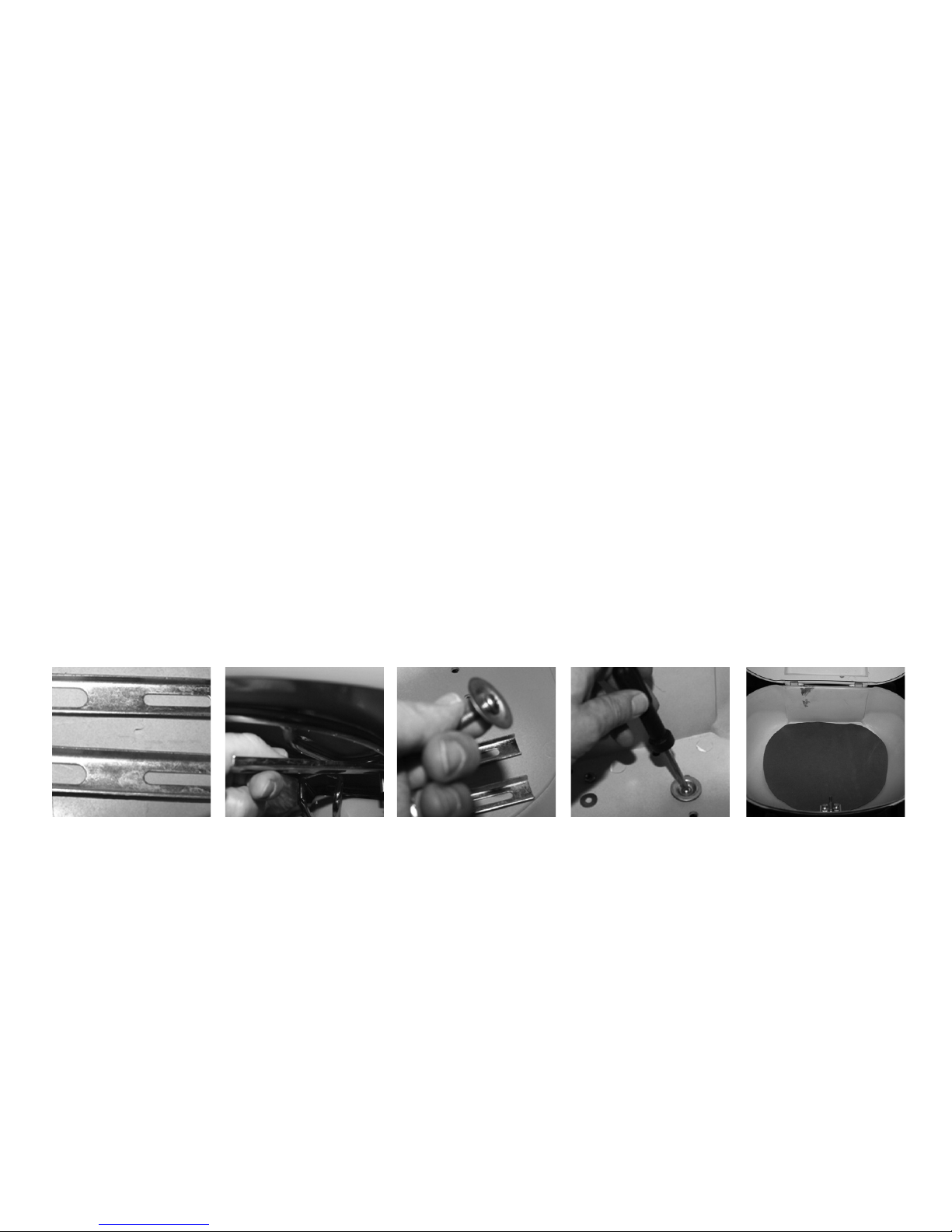
7
Top box
The top box is supplied with a universal tting kit. Place the top box
centrally on the rack. Hold the long slotted bars under the rack with the edges
of the bars facing upwards. Put the long screw and washer through the holes
in the box and then through the slide underneath the rack. Fix in place and
tighten with the nuts and washers provided. Cover the screws with the mat provided.
A maximum weight of 10 kilos is recommended. The weight may also alter the
handling of the scooter.
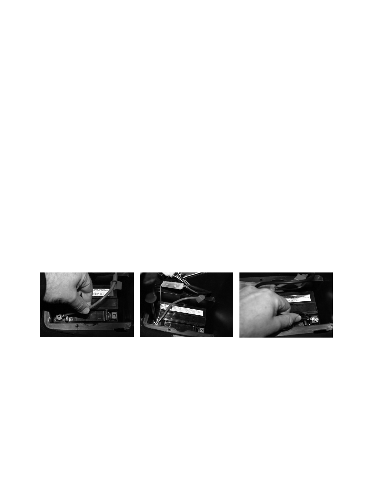
8
Fitting the battery
Make sure the scooter ignition is in the off position. Put the battery in the
compartment.
Fit the 2 red leads (sometimes one or both of these leads are covered by a
protective black sleeve, if you lower the sleeves you will see the red leads) to the +
side (also marked red on the terminal.) using the screw provided.
The black lead is then tted with the crew provided to the - negative side.
If the battery needs to be charged you may use a car battery charger or take it to
your local approved dealer for a boost.
9
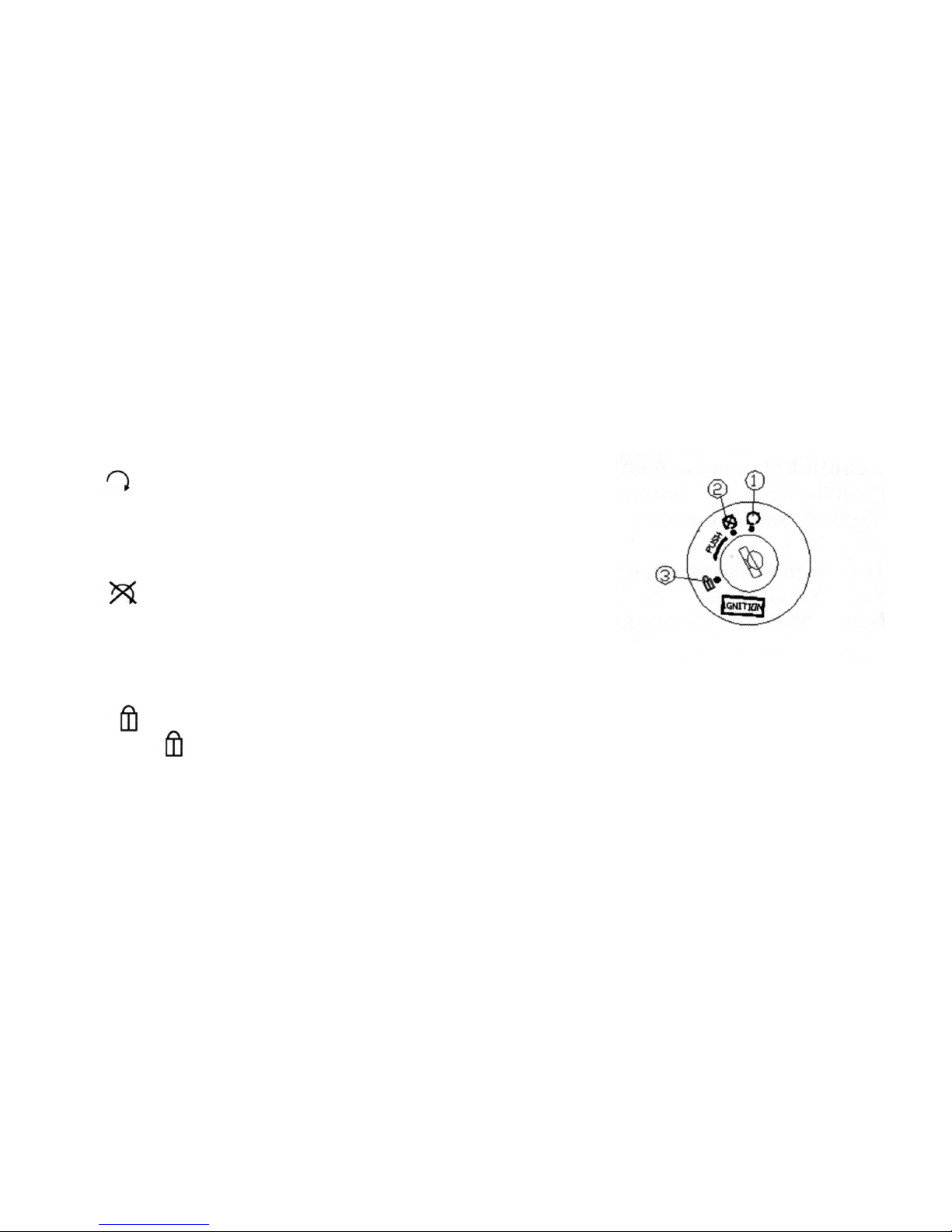
Guide to Operation
Ignition Switch
(1) position Turn the switch this position
to start the engine; the switch key can not
be pulled out in this position.
(2) position Turn the switch to this position
to shut down the engine; the switch key can
be pulled out in this position.
(3) position Turn the switch all the way to the left, push it down and turn
to the position; the key can be pulled out. In this case, the vehicle can
not be steered and the engine as well as the lighting system will not work.
 Loading...