

Direct Bikes DB50QT-A, DB125T-9, DB125T-E User Manual
Manual-DB50QT-A

1
Dear Customer:
Thank you for purchasing the Direct Bikes DB50QT-A scooter.
The Direct Bikes DB50QT-A scooter is manufactured using some of the most
advanced production techniques in the world. The scooter features high
performance, economic fuel consumption and low noise levels. This manual
provides detailed information about the correct operation, maintenance and
adjustment of your DB50QT-A scooter. Please read this manual carefully to
ensure safety and maximum ease of use.

2
Important Notice:
• Driver and passenger
This vehicle is designed to carry only one driver and one passenger. The
driver is required to have the appropriate licence for these requirements.
Do not exceed the rated load capacity specied on the specication label.
• Road condition
This vehicle is designed to travel on at roads. Do not ride this vehicle in
freezing or hazardous conditions.
• Modications
This vehicle should not be modied.
CAUTION:
Personal injury or mechanical damage may result if you fail to operate
as instructed in the manual.
3
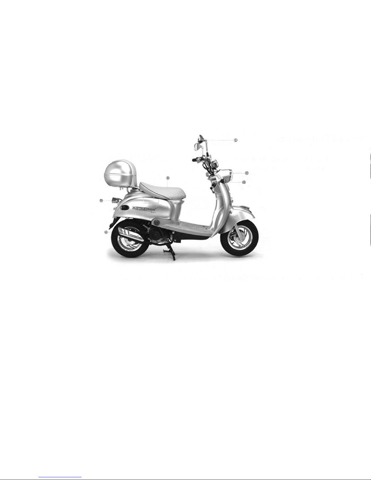
Location of Component parts
(1) Back-view mirror (2) Headlight (3) Front turn signal light
(4) Mufer (5) Taillight (6) Seat
4
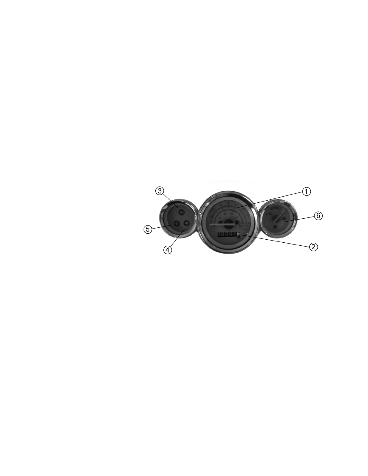
Meter Panel and Indicators
All the controls for the indicators and warning lights are located on the meter
panel.
(1) Speedometer
(2) Mileometer
(3) High beam indicator
(4) Turn right signal light
(5) Turn left signal light
(6) Fuel meter
Fuel gauge
The fuel gauge indicates the approximate amount of fuel remaining in the fuel
tank. When the needle pointer stays in the F(full) position, it means the total
capacity of the fuel tank is now 6.0 litres (including reserve fuel). When the
needle pointer approaches the rst dot on the red mark, it means that the fuel
tank must be relled immediately.

5
Identication
The VIN or chassis number is located on the frame of the scooter and is
either under the seat or under the clip in cover in the front of the foot well.
The engine number is located on the left side on the bottom of engine.
NOTE:
You should regard this manual as a permanent component part of your
vehicle, it is essential for the continued operation and safety of your
scooter to perform periodic servicing by an approved dealer. This is
required under your warranty.

6
Fitting the accessories
Mirrors
The mirrors come ‘handed’, i.e. a left and right one. They screw into either the left
and right switch gear or into the front and back brake lever assemblies.
There is a lock nut on the threaded part of the mirror to ensure the mirror does not
come loose. Wind this lock nut up as far as it will go and carefully screw the mirror
into the mount.
It is important you do not ‘cross thread’ the mirror as it will damage the mount. When
the mirror is in as far as it will go sit on the motorcycle and make sure you can see
behind you. Once done move the lock nut down and tighten being careful not to
over tighten. Finish by sliding the rubber boot down over the lock nut.
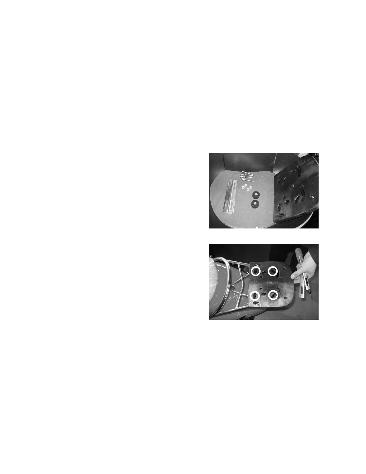
Top box
7
Check the accessories.
Put the plastic bottom-board centrally
on the rear bracket, notice the four
holes highlighted in photo with white
circles.
2.
1.
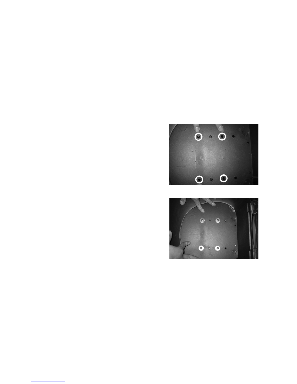
Put the top box centrally on the
plastic bottom-board, notice the four
holes inside the top box highlighted in
photo with white circles.
With these four holes (highlighted in
white circles in gure 3) insert the 4
bolts and 4 washers.
8
3.
4.
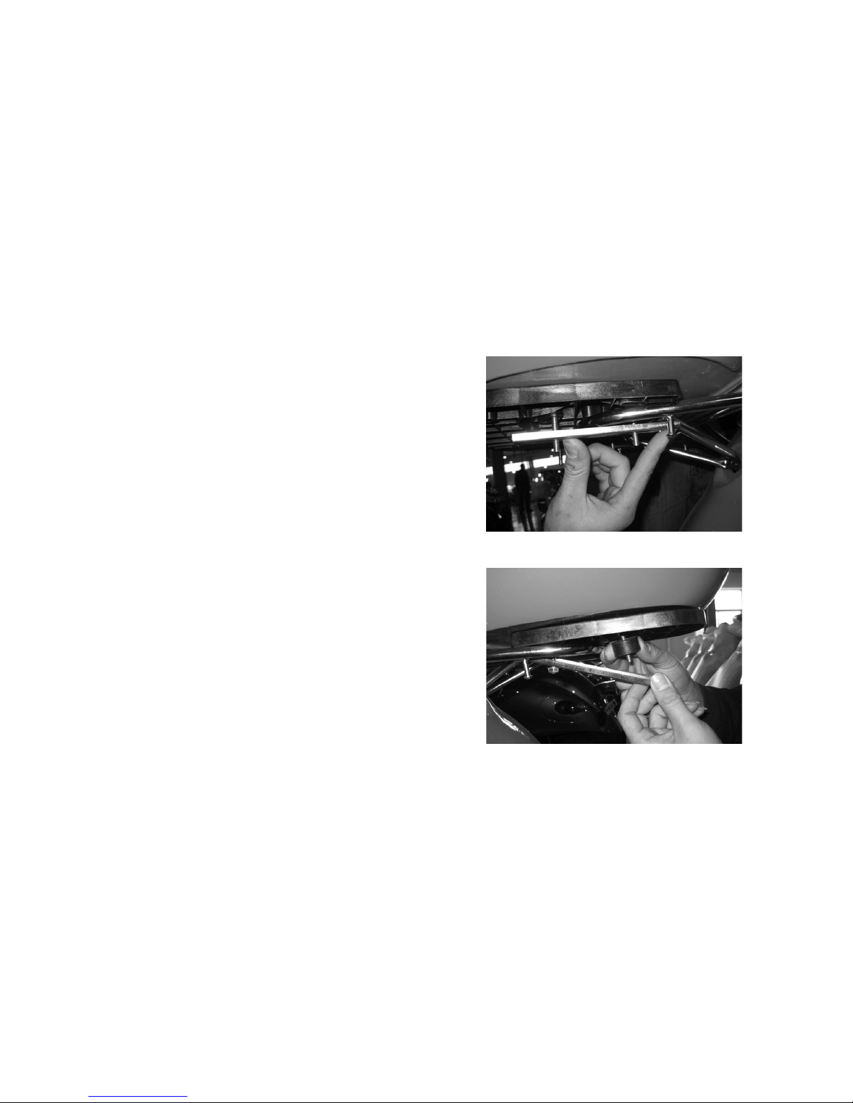
Insert the bolts through the four aligned
holes in the bottom-board (highlighted
in white circles in gure 2). Hold the
long slotted bars under the rack with
the edges of the bars facing upwards.
Put the bolts through the holes of the
slotted bars.
Attach nuts to the bolts nearest the tail
of the scooter. With the further bolts
attach the rubber buffers in between the
slotted bars and bottom-board.
9
5.
6.

10
Attach nuts and tighten up all bolts.
This process is completed on both
sides of the top boxes so both slotted
bars are attached and secure.
8.
7.
 Loading...