

DirectBikes DB125T-13 User Manual

Introduction
DirectBikes thanks you for purchasing your new
DB125T-13 motorcycle. We produce our
motorcycles using some of the most advanced
production techniques in the world.
We want you to enjoy your new machine and have
compiled a basic manual for you that covers the
assembly out of the crate and the basic
maintenance. Please read carefully. If in any doubt
consult a suitably qualified person or our technical
department.
Proper assembly and maintenance will ensure your
safety and the long service life of the machine.
Identification
The VIN or chassis number is located on the frame
of the motorcycle and is either under the seat or
under the clip in cover in the front of the footwell.
The engine number is located on the left side on the
bottom of engine.
Tools
Please have a selection of good quality tools ready
which include; Cutters, knife, hammer, 8, 10, 12, 13,
14, 17mm sockets and spanners, ratchet, extension
bar, flat screwdriver’s, Philip screwdriver’s, pliers,
magnetic tray, lube, multi-purpose grease and
cleaning cloths.
Before starting check the model details against the
invoice details and any signs of damage to the box.
The Crate
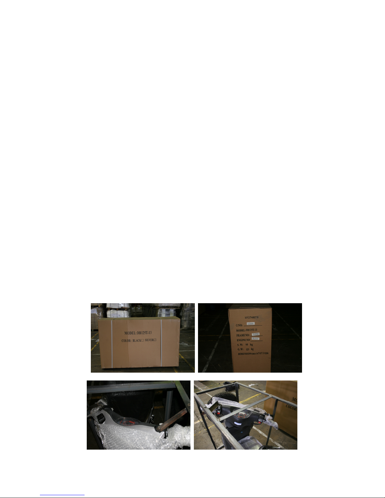
Please ensure you have adequate space. Using
scissors cut the nylon bands that surround the box
and discard. Cut the cardboard to reveal the steel
frame supporting the motorcycle. You will now need
a 13mm socket on a bar or ratchet and a 13mm
spanner. Undo the front wheel from the frame.
Undo all the lower nuts and bolts securing the upper
portion of the frame. Undo the bolts securing the
handlebars and the rear carry rack.
Wearing gloves and using two people, lift the upper
part of the frame off the motorcycle. Be careful not
to scratch the paintwork. The motorcycle is now
held in by only the front spindle. Stood at the rear of
the motorcycle, lift it out of the frame to the right and
put the centre stand down. One person holds the
back down whilst the other person undoes the
spindle and releases the motorcycle from the frame
completely. Discard the metal frame. Remove all
the protective packaging and the ancillaries from
the footwell.
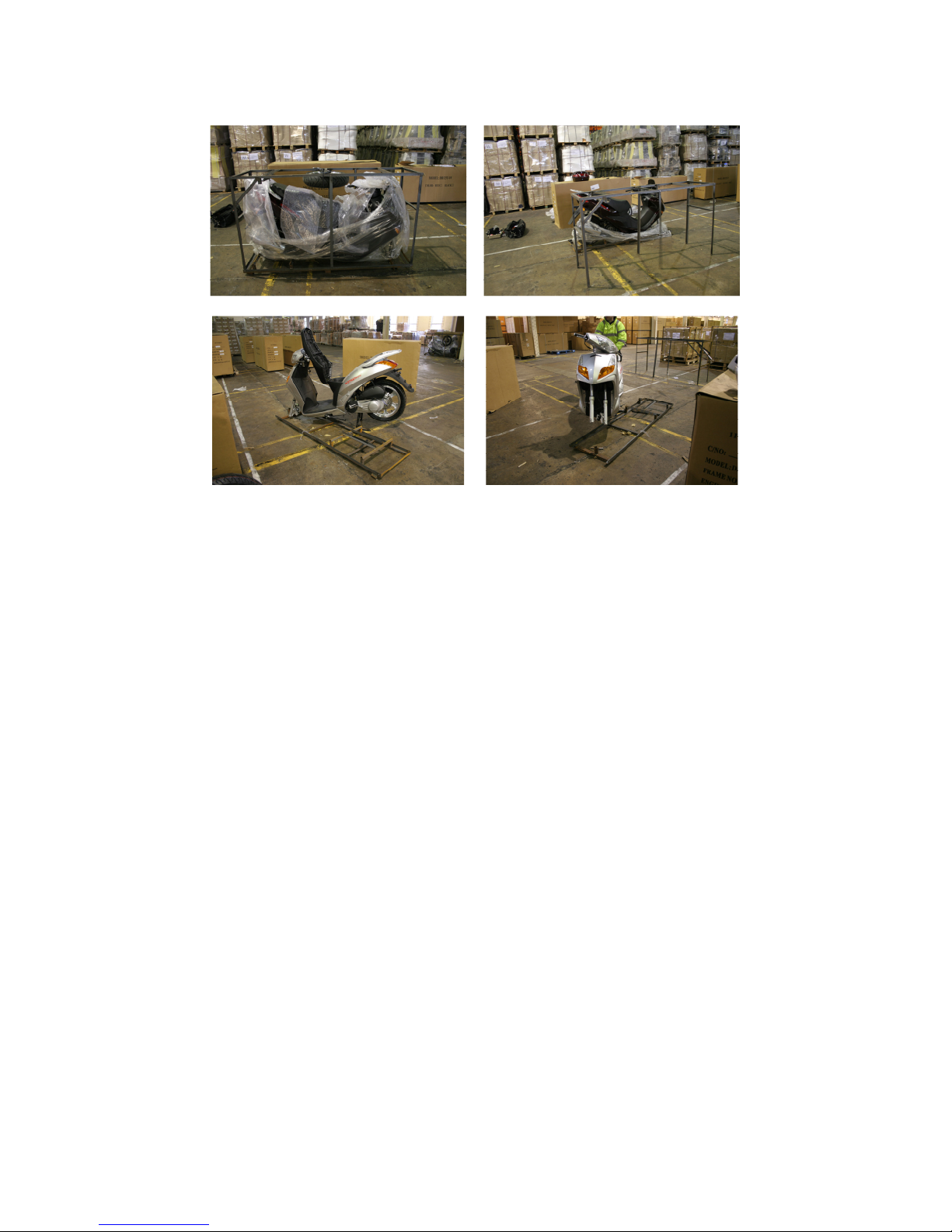
(Illustration only)
Assembly
Front wheel
With the back of the motorcycle still being held
down it is now possible to insert the front wheel.
Firstly remove the plastic wedge from the brake
calliper. Offer the wheel up in-between the forks so
the brake disc sits correctly in the calliper. It is
vitally important that the brake pads sit on either
side of the disc.
Next insert the front wheel spindle through the fork
leg to which the calliper is attached, through the
spacer into the wheel and through the speedo drive
into the opposite fork leg. Put the nut onto the
spindle finger tight. Now check that the speedo
drive is correctly located, double check that the disc
is correctly located and tighten up. Pump the front
brake lever till it goes hard. Lastly put the chrome
covers on the lower fork, left and right.
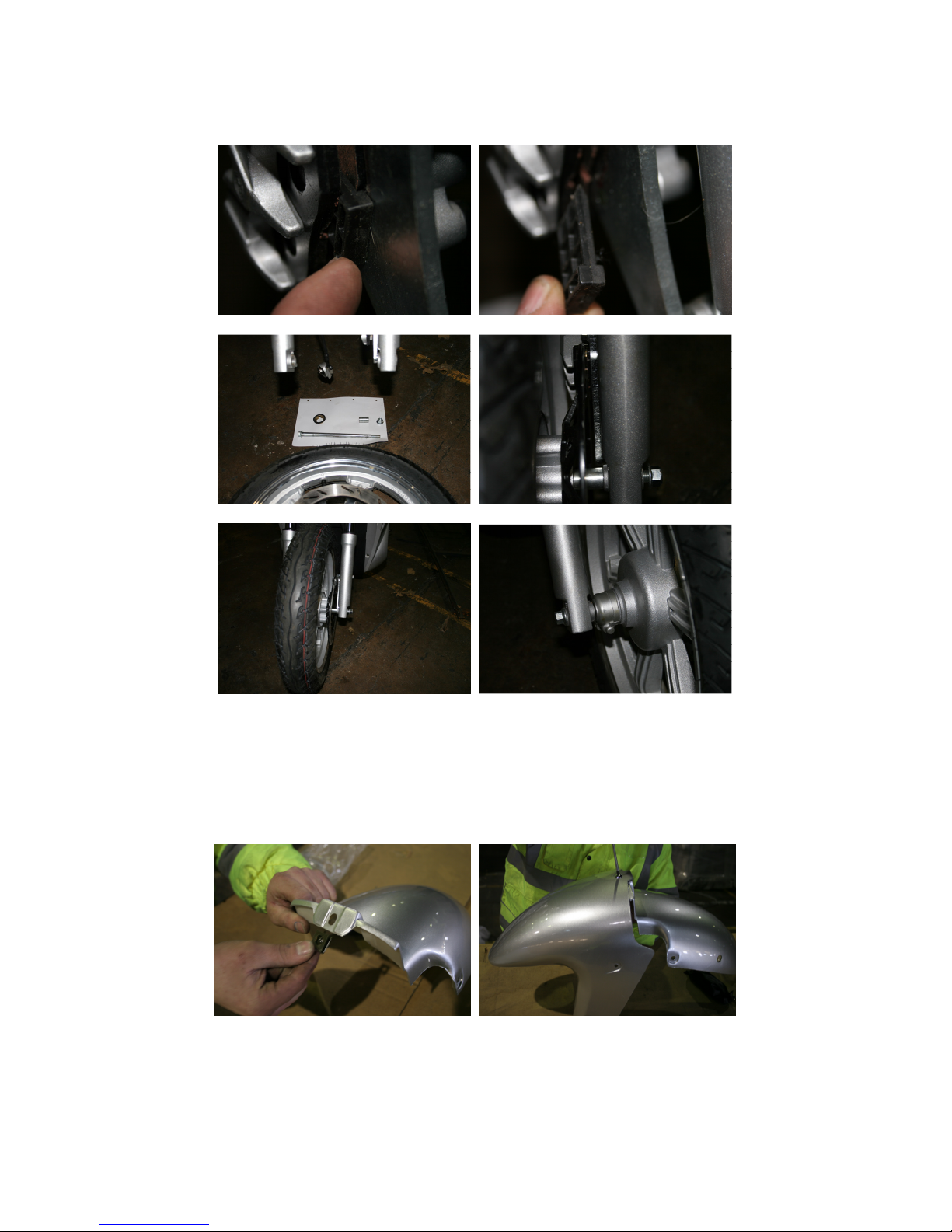
Front Mudguard
The front mudguard is in two halves, front and rear
and is held on by five screws and one clip.
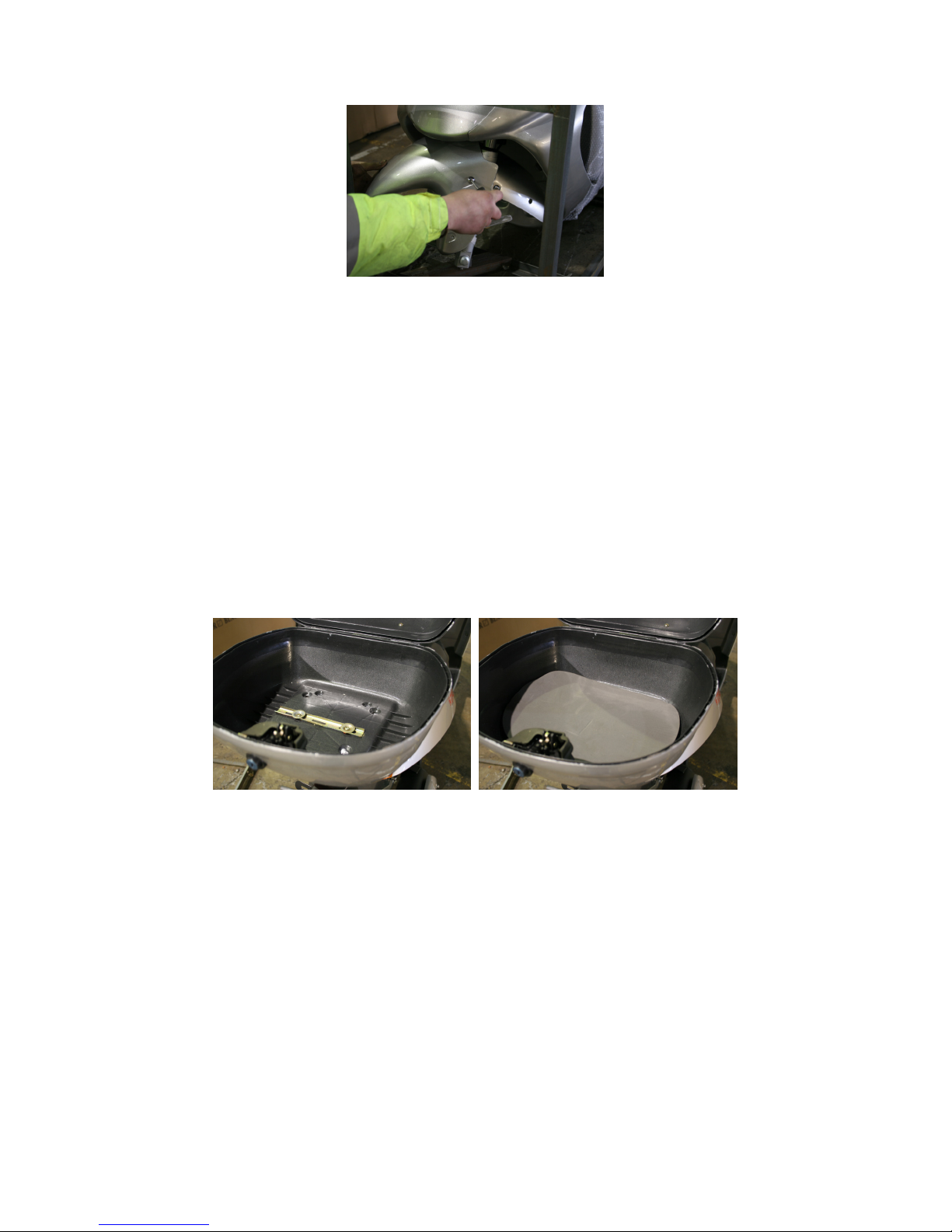
Top box
The top box is supplied with a universal fitting kit.
The two long slotted bars go on the inside of the
box. Put the long M6 screws (4 of) through the slots
and line the box on the rack so that it is central. Use
the 4 smaller slotted bars underneath. Fix in place
with the nuts and washers provided. Cover with the
protective foam mat A maximum weight of 10 kilos
is recommended. The weight may also alter the
handling of the motorcycle.
The mirrors come ‘handed’, i.e. a left and right one.
They screw into either the left and right switch gear
or into the front and back brake lever assemblies.
There is a lock nut on the threaded part of the
mirror to ensure the mirror does not come loose.
Wind this lock nut up as far as it will go and
carefully screw the mirror into the mount.
Mirrors
 Loading...