

Direct Air Room air conditioner Installation Manual
Before using your air conditioner, please read
this manual carefully and keep it for future reference.
ROOM AIR CONDITIONER
Please read this installation manual completely
before installing the product.
If the power cord is damaged, replacement work
shall be performed by authorised personnel only.
Installation work must be performed in accordance
with the national wiring Standards by authorised
personnel only.
Contact an authorised service technician for
repair, maintenance or installation of this unit.
INVERTER ONE-TWO / ONE-THREE
/ONE- FOUR/ONE-FIVE SPLIT-TYPE
1
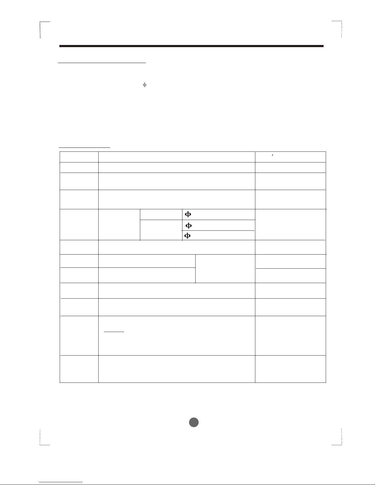
CONTENTS
SAFETY PRECAUTIONS
Warning ...........................................................................................................................................2
Caution ............................................................................................................................................2
INSTALLATION INSTRUCTIONS
Selecting installation place...............................................................................................................3
Wall-mounted type ...........................................................................................................................3
Accessories .........................................................................................................4
Four-way cassette type ................................................................................................................9
Duct & Ceiling type .......................................................................................................................12
Ceiling and Floor type ....................................................................................................................16
Floor and Standing type(Console)..................................................................................................19
Outdoor unit installation ................................................................................................................23
REFRIGERANT PIPE CONNECTION
Refrigerant pipe connection ..........................................................................................................24
Inside you will find many helpful hints on how to install and test the air conditioner properly.
All the illustrations and specifications in the manual are subject to change without prior notice for product
improvement. The actual shape should prevail.
Contact an authorised service technician for repair or maintenance of this unit.
Contact an authorised installer for installation of this unit.
The air conditioner is not intended for use by young children or infirmed persons without supervision.
Young children should be supervised to ensure that they do not play with the air conditioner.
If the power cord is to be replaced, replacement work shall be performed by authorised personnel only.
Installation work must be performed in accordance with the national wiring Standards by authorised
personnel only.
CAUTION
Read This Manual
ELECTRICAL WORK
Electrical work .................. ...........................................................................................................25
TEST RUNNING
Test running ..................................................................................................................................30
AIR PURGING
Air purging with vacuum pump .....................................................................................................27
Safety and leakage check ............................................................................................................29
2
SAFETY PRECAUTIONS
WARNING
Read the follow SAFETY PRECAUTIONS carefully before installation.
Electrical work must be installed by a licensed electrician. Be sure to use the correct rating
of the power plug and main circuit for the model to be installed.
Incorrect installation due to ignoring of the instruction will cause harm or damage.
The seriousness is classified by the following indications.
This symbol indicates the possibility of death or serious injury.
The items to be followed are classified by the symbols:
Symbol with background white denotes item that is PROHIBITED from doing.
CAUTION
This symbol indicates the possibility of injury or damage to property.
WARNING
1) Engage dealer or specialist for installation. If installation done by the user is defective, it will cause water
leakage, electrical shock fire.
2) Install according to this installation instructions strictly. If installation is defective, it will cause water
leakage, electrical shock fire.
3) Use the attached accessories parts and specified parts for installation. otherwise, it will cause the set to fall,
water leakage, electrical shock fire.
4) Install at a strong and firm location which is able to withstand the set s weight. If the strength is not enough
or installation is not properly done, the set will drop and cause injury.
,
5) For electrical work, follow the local national wiring standard, regulation and this installation instructions. An
independent circuit and single outlet must be used. If electrical circuit capacity is not enough or defect found
in electrical work, it will cause electrical shock fire.
6) Use the specified cable and connect tightly and clamp the cable so that no external force will be acted on
the terminal. If connection or fixing is not perfect, it will cause heat-up or fire at the connection.
7) Wiring routing must be properly arranged so that control board cover is fixed properly. If control board cover
is not fixed perfectly, it will cause heat-up at connection point of terminal, fire or electrical shock.
8) When carrying out piping connection, take care not to let air substances other than the specified
refrigerant go into refrigeration cycle. Otherwise, it will cause lower capacity, abnormal high pressure
in the refrigeration cycle, explosion and injury.
9) Do not modify the length of the power supply cord or use of extension cord, and do not share the
single outlet with other electrical appliances. Otherwise, it will cause fire or electrical shock.
CAUTION
1) This equipment must be earthed and installed with earth leakage current breaker. It may cause electrical
shock if grounding is not perfect.
2) Do not install the unit at place where leakage of flammable gas may occur. In case gas leaks and
accumulates at surrounding of the unit, it may cause fire.
3) Carry out drainage piping as mentioned in installation instructions. If drainage is not perfect, water
may enter the room and damage the furniture.
3
Selecting installation place
Read completely, then follow step by step.
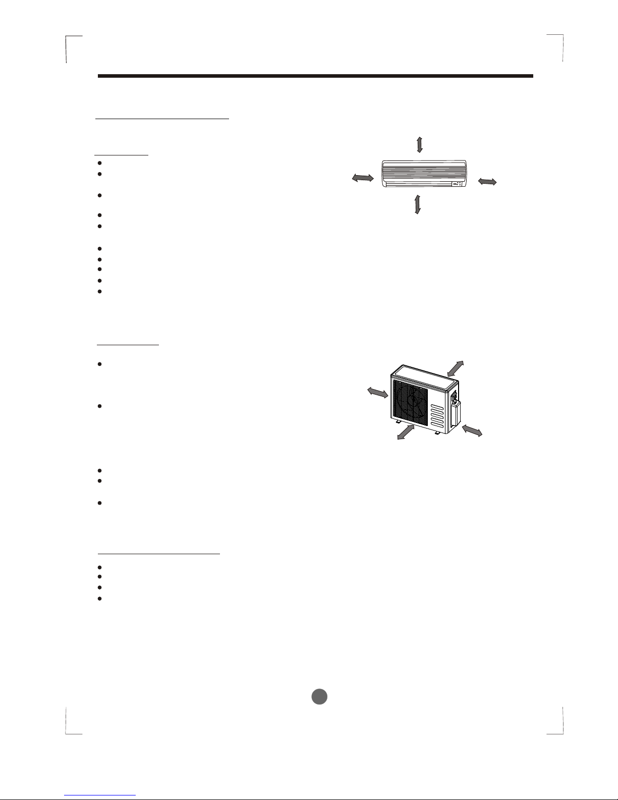
Indoor unit
Do not expose the indoor unit to heat or steam.
Select a place where there are no obstacles
in front or around the unit.
Make sure that condensation drainage can
be conveniently routed away.
Do not install near a doorway.
Ensure that the space on the left and right
of the unit is more than 12cm.
Use a stud finder to locate studs to prevent unnecessary damage to the wall.
The indoor unit should be installed on the wall at a height of 2.0 metres or more from the floor.
The indoor unit should be installed allowing a minimum clearance of 15cm from the ceiling.
Any variations in pipe length will/may require adjustment to refrigerant charge.
There should not be any direct sunlight. Otherwise, the sun will fade the plastic cabinet and
affect its appearance. If unavoidable, sunlight prevention should be taken into consideration.
Outdoor unit
If an awning is built over the outdoor unit to
prevent direct sunlight or rain exposure,
make sure that heat radiation from the
condenser is not restricted.
Ensure that the clearance around the back
of the unit is more than 30cm and left side is
more than 30cm. The front of the unit should
have more than 200cm of clearance and the
connection side (right side) should have more
than 60cm of clearance.
Do not place animals and plants in the path of the air inlet or outlet.
Take the air conditioner weight into account and select a place where noise and vibration
will not be an issue.
Select a place so that the warm air and noise from the air conditioner do not disturb neighbors.
If the outdoor unit is installed on a roof structure, be sure to level the unit.
Ensure the roof structure and anchoring method are adequate for the unit location.
Consult local codes regarding rooftop mounting.
If the outdoor unit is installed on roof structures or external walls, this may result in
excessive noise and vibration, and may also be classed as a non serviceable installation.
Rooftop installation:
INSTALLATION INSTRUCTIONS
More than
30cm
M
ore
than 60c
m
M
ore
th
an
3
0c
m
More
than
2
00cm
Fig.2
More than 2.0m
More than 15cm
More than 12cm
More than 12cm
Fig.1
1. Wall-mounted type
4
Accessories
INSTALLATION INSTRUCTIONS
Note: Except the above parts provided, the other parts needed during installation you must
purchase.
Parts you must purchase
Consult the technician
for the proper size.
6.35
9.53
12.7
6
2
Self-tapping Screw B ST2.9X10
Remote controller
Installation Plate
Name of Accessories
Self-tapping Screw A ST3.9X25
Seal (for cooling& heating models only)
Drain Joint
Magnetic ring
(Hitch it on the connective cable between indoor
unit and outdoor unit after installation.)
Transfer connector( )
(NOTE: Pipe size differ from appliance to appliance.
To meet different pipe size requirement, sometimes
the pipe connections need the transfer connector
to install on the outdoor unit .)
Packed with the indoor unit
Connecting
pipe
Assembly
Liquid side
Plastic Expansion Sheath
Number
Q ty/one unit
Gas side
7
Remote controller holder
1
(for cooling& heating models only)
1
5-8
(depending on models)
5-8
(depending on models)
1
1
1
1
(on some models)
1
5
4
9
11
10
8
3
2
1
Level gauge
Screwdriver
Electric drill,Hole core drill ( 65mm)
Flaring tool set
Specified torque wrenches: 1.8kgf.m, 4.2kgf.m,
5.5kgf.m, 6.6kgf.m(different depending on model No.)
Spanner (half union)
Hexagonal wrench (4mm)
Gas-leak detector
Tools needed for installation:
Vacuum pump
Gauge manifold
Users manual
Thermometer
Multimeter
Pipe cutter
Measuring tape
Optional
parts
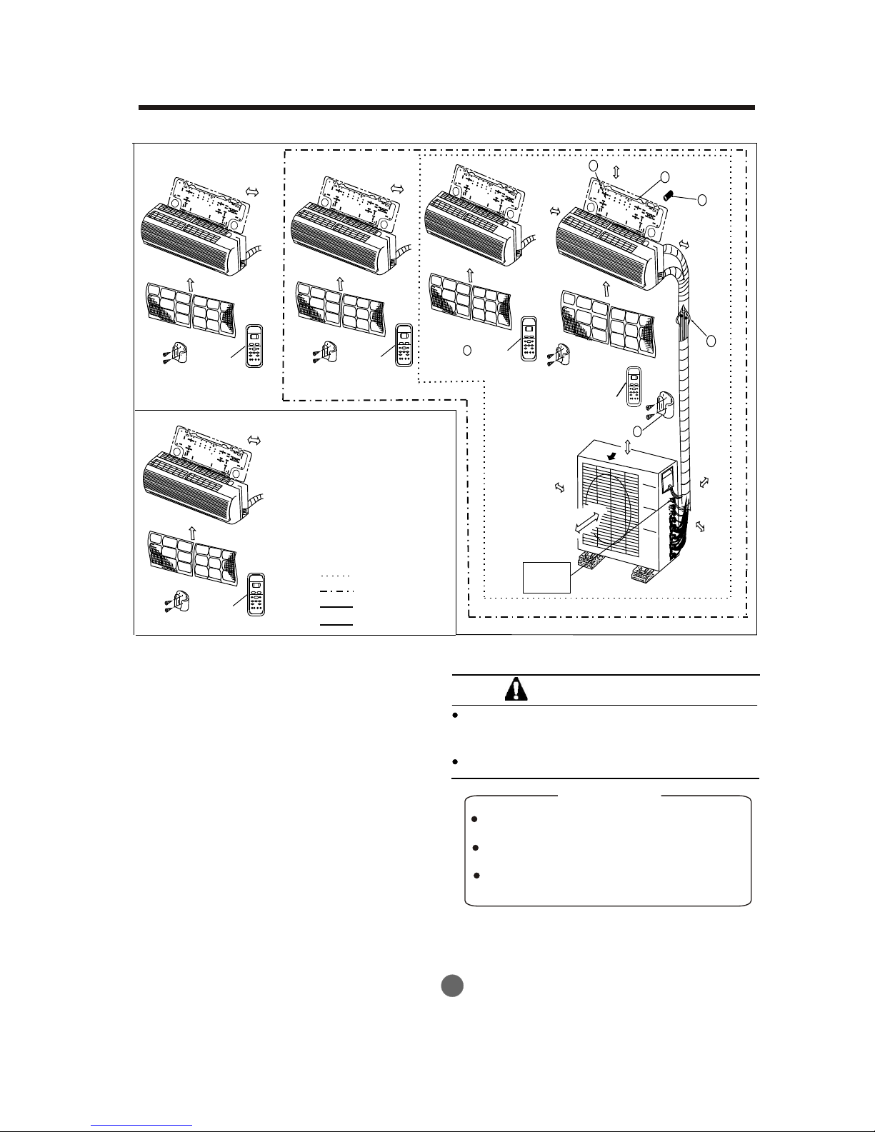
This illustration is for explanation purposes only.
The actual shape of your air condtioner may be
slightly different.
Copper lines must be insulated independently
Use a stud finder to locate studs to prevent
unnecessary damage to the wall.
A minimum pipe run of 3 metres is required
to minimise vibration & excessive noise.
Two of the A, B and C directions should be
free from obstructions.
CAUTION
INSTALLATION INSTRUCTIONS
5
CAUTIONS
One-Two
One-Three
One-Four
One-Five
More than 12cm
More than 12cm
Air filter
Air filter
Remote
controller
Remote
controller
More than 12cm
Air filter
Remote
controller
Remote
controller
Air filter
More than
12cm
More than 15cm
More than
12cm
Air filter
Remote
controller
More than
10cm
A
B
C
Mor
e
th
an 2
00
cm
Air out
Mo
r
e
t
h
a
n
60cm
More
than
30cm
Mor
e than
60c
m
Loop a
connective
cable
1
2
3
4
5
6
Fig.3
6
INSTALLATION INSTRUCTIONS
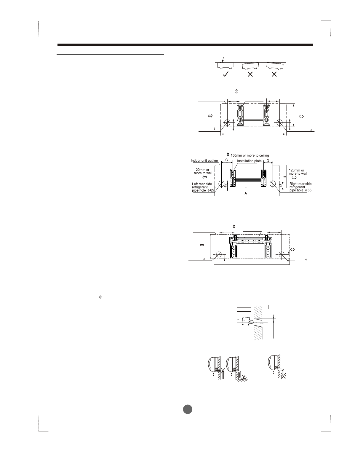
Fig.4
Correct orientation
of Installation Plate
Wall
Indoor
Outdoor
5-7mm
Fig.6
Fig.5
Indoor unit installation(wall-mounted type)
2. Drill a hole in the wall
Note:
1. Fit the Installation Plate
1. Fit the installation plate horizontally
on structural parts of the wall with
spaces around the installation plate.
2. If the wall is made of brick, concrete
or the like, drill five or eight 5mm diameter
holes in the wall.Insert Clip anchor for
appropriate mounting screws.
3. Fit the installation plate on the wall
with five or eight type “A” screws.
Fit the Installation Plate and drill
holes in the wall according to the
wall structure and corresponding
mounting points on the installation
plate. The Installation Plate may be
slightly different according to the
different models of indoor unit.
(Dimensions are in “mm” unless
otherwise stated)
1. Determine hole positions according
to the diagramdetailed in Fig.5. Drill
one (1) hole ( 65mm) slanting slightly
to outdoor side.
2. Always use wall hole conduit when
drilling metal grid, metal plate or the like.
3. Connective Pipe and Drainage
Installation
1. Run the drain hose sloping downward.
Do not install the drain hose as
illustrated in Fig.7.
Drainage
Fig.7
Do not block water flow by a rise.
Do not put the end of
drain hose into water.
150mm or more to ceiling
Indoor unit outline
Installation plate
292
Right rear side
refrigerant
pipe hole 65
Left rear side
refrigerant
pipe hole 65
120mm or
more to wall
120mm or
more to wall
918
45
190
150
45
A
45
B
Right rear side
refrigerant
pipe hole 65
Installation plate
Indoor unit outline
Left rear side
refrigerant
pipe hole 65
150mm or more to ceiling
120mm or
more to wall
120mm or
more to wall
Model A (A: 710, B: 250, C:100, D: 110)
Model A (A: 710, B: 250, C:100, D: 110)
Model A (A: 920, B: 293, C:150, D: 185)
Model B( )A: 790, B:265, C:100, D: 150
Model B( )A: 790, B:275, C:100, D: 85
Model C( )A: 850, B:290, C:100, D: 115
Model B( )A: 995, B:293, C:150, D:200
Model C( )A: 850, B:305, C:150, D:145
45
C
D
7
INSTALLATION INSTRUCTIONS
1. For the left-hand and right-hand piping,
remove the pipe cover from the side
panel.
2. For the rear-right-hand and rear-left-hand
piping, install the piping as shown in Fig.10.
3. Fix the end of the connective pipe. (Refer
to Tightening Connection in REFRIGERANT
PIPING CONNECTION)
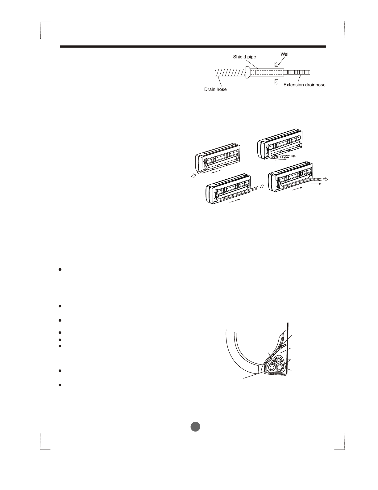
Connective pipe installation
2. When connecting extension drain hose,
insulate the connecting part of extension
drain hose with a shield pipe, do not let
the drain hose slack.
Right-hand piping
Left-hand piping
Rear-right piping
Rear-left piping
Fig.8
Fig.9
Fig.10
4. Piping and wrapping
Bundle the tubing, connecting cable, and drain
hose with tape securely, evenly as shown in
Fig.11.
Because the condensed water from rear of the
indoor unit is gathered in ponding box and is
piped out of room. Do not put anything else in
the box.
Indoor unit
Connective
pipe
Pipe room
Ponding box
Wrapping belt
Connective
cable
Drain hose
Fig.11
Connect the indoor unit first, then the
outdoor unit.
Do not allow the piping to let out from
the back of the indoor unit.
Be careful not to let the drain hose slack.
Heat insulated both of the auxiliary piping.
Be sure that the drain hose is located at
the lowest side of the bundle. Locating
at the upper side can cause drain pan
to overflow inside the unit.
Never intercross nor intertwist the power
wire with any other wiring.
Run the drain hose sloped downward to
drain out the condensed water smoothly.
CAUTION
8
INSTALLATION INSTRUCTIONS
Fig.12
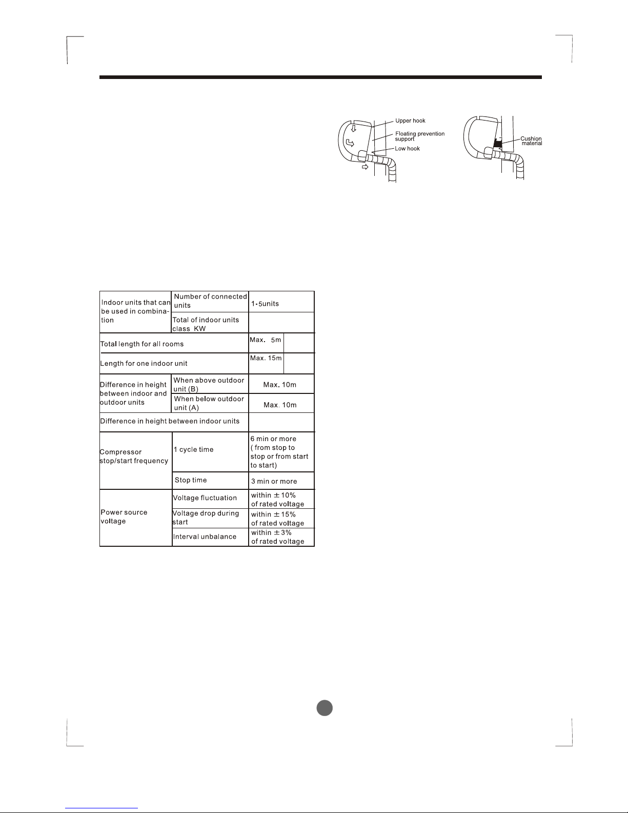
1. Pass the piping through the hole in the
wall.
2. Put the upper claw at the back of the
indoor unit on the upper hook of the
installation plate, move the indoor unit
from side to side to see that it is securely
hooked (see Fig.12).
3. Piping can easily be made by lifting the
indoor unit with a cushioning material
between the indoor unit and the wall.
Get it out after finish piping.
4. Push the lower part of the indoor unit up
on the wall, then move the indoor unit
from side to side, up and down to check
if it is hooked securely.
4. Indoor unit installation
(R410A)
Max. 50m
(R407c/R22)
Max.10m
Max.5m
(R410A)
(R407c/R22)
10.5KW
7

2. Four-way cassette type
1. Decide the correct carry-in path.
2. Move this unit as originally packaged as possible.
3. If the air conditioner is installed on a metal part
of the building, it must be electrically insulated
according to the relevant electrical code.
4. If installing in a lonely building or at a high position
where it is hot and humid with frequent thunder storm, lightning-protection equipment is necessary.
Notes before installation
1. Install the main body
A. The existing ceiling (to be horizontal)
a. Please cut a quadrangular hole of 600 600mm
in the ceiling according to the shape of the
installation paper board. (Refer to Fig.15 & 16)
The center of the hole should be at the same
position of that of the air conditioner body.
Determine the lengths and outlets of the conn ecting pipe, drain pipe and cables.
To balance the ceiling and to avoid vibration,
please enforce the ceiling when necessary.
b. Please select the position of installation hooks
according to the hook holes on the installation
board.
Drill four holes of 12mm, 50~55mm deep at the
selected positions on the ceiling. Then embed
the expansible hooks(fittings).
Face the concave side of the installation hooks
toward the expansible hooks. Determine the
length of the installation hooks from the height
of ceiling, then cut off the unnecessary part.
If the ceiling is extremely high, please determine
the length of the installation hook according to
facts.
Cut the installation hook open in the middle
position, then use apropriate length of reinforcing
rod ( 12) to weld together.
Indoor unit installation
9
INSTALLATION INSTRUCTIONS
Please check whether the following fittings are of full scope. If there are some attached fittings free
from use, please restore them carefully.
Installation Fittings
Tubing & Fittings
1. Expansible hook.................................4
2. Installation hook.................................4
3. Installation paper board.....................1
4. Bolt M5 16 or M6 12.....................4
Attached fittings
6. Connecting pipe group.........................1
8. Soundproof / insulation sheath.............2
7. Binding tape.........................................6
Remote controller & Its Frame
9. Remote controller...........................1
10. Frame.............................................1
11. Mounting screw(ST2.9 10-C-H) ...2
12. Alkaline dry batteries (AM4)............2
5. Magnetic ring..........................................1
A 280
Necessary roomNecessary room
Fig.13
Fig.14
Ground
Outlet
Outlet
>2300
Inlet
>1000
>1000
>1000
>1000
Fig.15
Drain side
A
422 28.5
67
401(Hook location)
611(Hook location)
580(Body)
580(Body)
600(Ceiling hole)
600(Ceiling hole)
650(Panel)
650(Panel)
(on some models)
 Loading...