

Direct Air PHRV, PHRVR96 Installation, Operation And Maintenance Manual
PHRV
Heat Recovery Ventilator
INSTALLATION, OPERATION AND MAINTENANCE MANUAL
The Best
Limited Warranty
in the Business
• The heat recovery aluminum core has a
limited lifetime war
• The motors found in all Powrmatic HRV’s
require no lubrication, and are factory
balanced to prevent vibration and promote
ilent operation.
s
• The limited warranty covers normal use.
It does not apply to any defects,
malfunctions or failures as a result of
improper installation, abuse, mishandling,
misapplication, fortuitous occurrence or
any other circumstances outside
Powrmatic’s control.
• Inappropriate installation or
maintenance may result in the
cancellation of the war
• Any unauthorized work will result in
the cancellation of the warranty.
• Powrmatic is not responsible for any
incidental or consequential damages
incurred in the use of the ventilation
system.
• Powrmatic is not responsible for providing
an authorized service centre near the
purchaser or in the general area.
• Powrmatic reserves the right to supply
refurbished parts as replacements.
• Transportation, removal and installation
fees are the responsibility of the purchaser.
• The purchaser is responsible to adhering
to all codes in effect in his area.
• The warranty is limited to 5 years on
parts and 7 years on the motor from the
date of purchase, including parts replaced
during this time period. If there is no
proof of purchase available, the date
associated with the serial number will be
used for the beginning of the warranty
period.
* This war
ranty is the exclusive and only
warranty in effect relative to the ventilation
system and all other warranties either
essed or implied are invalid.
expr
***Illustrations &
images in this
manual may not be
exactly like unit
pur
illustrations &
images are for
examples only.***
ranty.
ranty.
chase, these
TABLE OF CONTENTS
TECHNICAL DATA
PHRVR96 . . . . . . . . . . . . . . . . . . . . . . . . . . . . . . . . . . . . . . . . . . . . . . . . . . . . .3
INSTALLATION . . . . . . . . . . . . . . . . . . . . . . . . . . . . . . . . . . . . . . . . . . . . . . . . . . . . .5
Mounting the Unit . . . . . . . . . . . . . . . . . . . . . . . . . . . . . . . . . . . . . . . . . . . . . . .5
Location & Ducting . . . . . . . . . . . . . . . . . . . . . . . . . . . . . . . . . . . . . . . . . . . . . . 6
xamples . . . . . . . . . . . . . . . . . . . . . . . . . . . . . . . . . . . . . . . . . . . . . . . . . . . . . .8
E
ir Flow Balancing . . . . . . . . . . . . . . . . . . . . . . . . . . . . . . . . . . . . . . . . . . . . . 10
A
OPERATION . . . . . . . . . . . . . . . . . . . . . . . . . . . . . . . . . . . . . . . . . . . . . . . . . . . . . .11
Modes Of Operation . . . . . . . . . . . . . . . . . . . . . . . . . . . . . . . . . . . . . . . . . . . . . . . .11
Optional Remote Controls . . . . . . . . . . . . . . . . . . . . . . . . . . . . . . . . . . . . . . . . 12
MAINTENANCE . . . . . . . . . . . . . . . . . . . . . . . . . . . . . . . . . . . . . . . . . . . . . . . . . . . 13
TROUBLESHOOTING . . . . . . . . . . . . . . . . . . . . . . . . . . . . . . . . . . . . . . . . . . . . . . . .14
ELECTRICAL CONNECTIONS . . . . . . . . . . . . . . . . . . . . . . . . . . . . . . . . . . . . . . .... 15
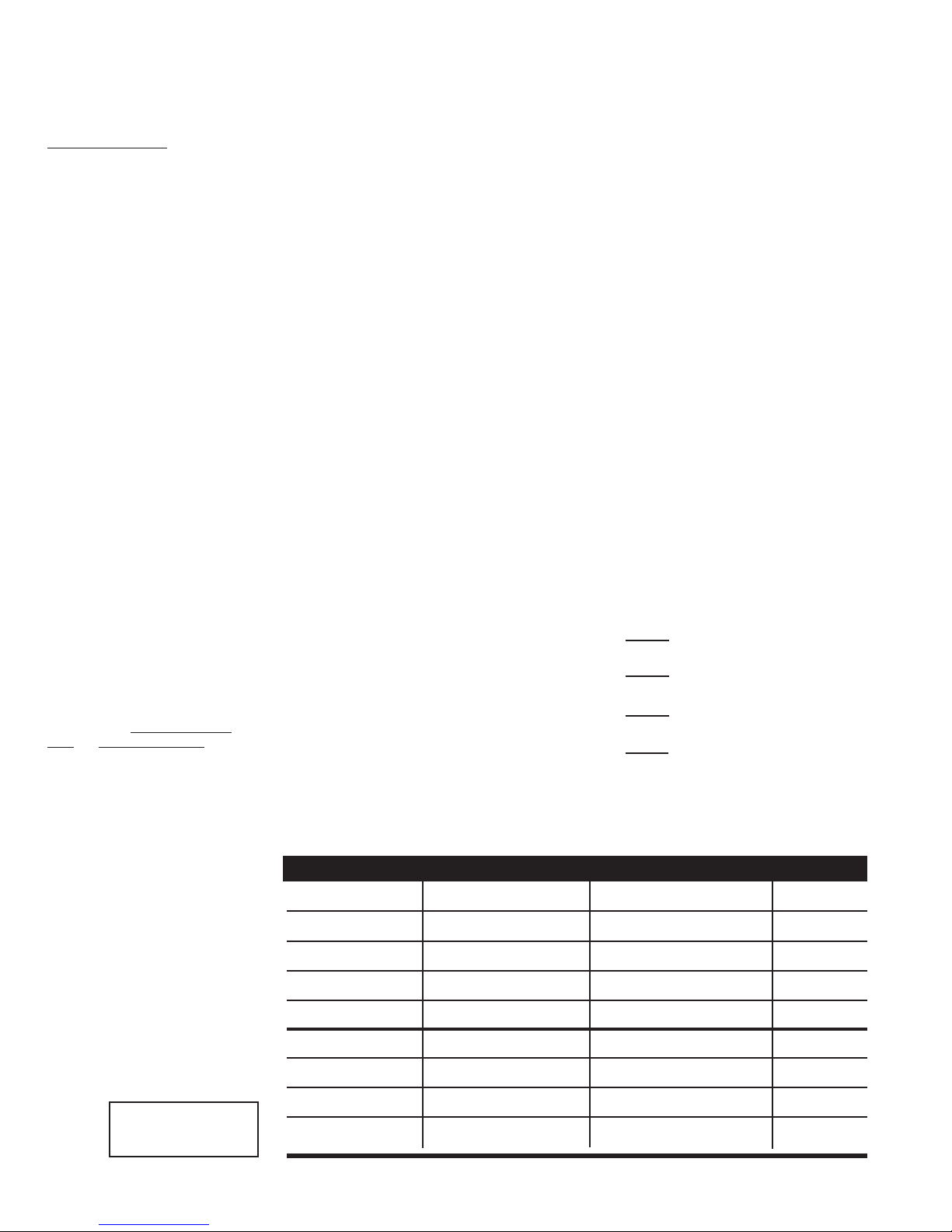
Sizing (Example) for maximum airflow normally required.
HRVs are typically sized to ventilate the whole house at a minimum of 0.35 air changes per
hour. To calculate, simply take the square footage of the house (including basement) and multiply by the height of the ceiling to get cubic volume. Then, divide by 60 and multiply by 0.35.
Example: SQFT of House 1100
Basement 1100
Total SQFT 2200
Height of ceiling x 8
Cubic volume 17600
/ 60
Maximum airflow required (CFM) 293
x 0.35
103
* Always consult your local code for sizing requirements in your area.
Alternate Method
Room classification Number of rooms CFM (L/s) CFM Required
Master bedroom x 20 cfm (10 l/s) =
Basement yes or no =
Bedrooms x 10 cfm (5 l/s) =
Living room x 10 cfm (5 l/s) =
Others x 10 cfm (5 l/s) =
Kitchen x 10 cfm (5 l/s) =
oom x 10 cfm (5 l/s) =
Bathr
if yes add 20 cfm / 10 l/s
if no = 0
1 cfm = 0.47189 l/s
Laundr
1 l/s = 3.6 m3/hr
2
Utility r
y r
oom
oom
entilation Requirements
otal V
T
x 10 cfm (5 l/s)
x 10 cfm (5 l/s) =
(add last column )
=
=
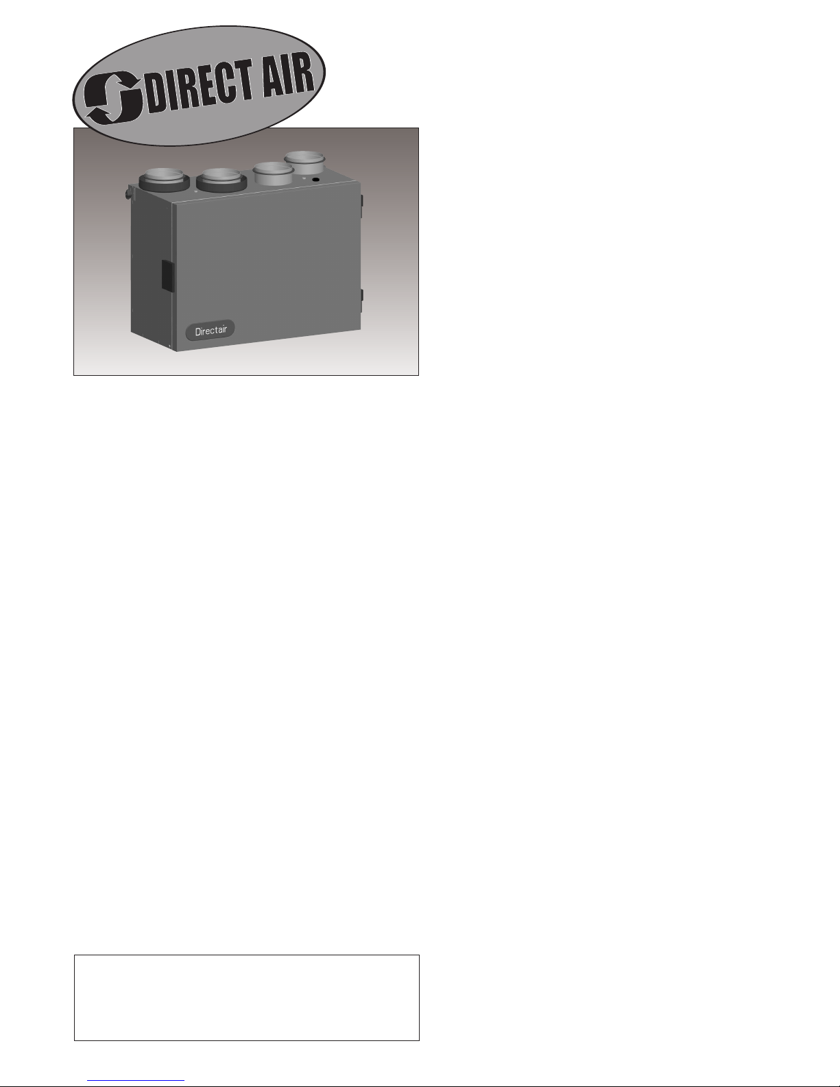
Compact top port design HRV with easy-mount wall bracket.
Brings a continuous supply of fresh air into a home while
exhausting an equal amount of contaminated air. HRVs use
what is called a “sensible” heat recovery core. This special
core transfers heat from the exhaust air stream to the
incoming air stream. Fresh incoming air is tempered by the
heat that is transferred from the outgoing air to save on
energy costs. The PHRV96 is equipped with automatic
defrost mechanisms so even if you live in the coldest climates you can use your HRV all year long.
FEATURES
• Super Compact Size
• Top Port Design Fits in Tight Spaces
• Includes Easy-Mount Wall Bracket
• Aluminum Heat Recovery Core
• 4” (100mm) Duct Connections
• No Balancing Required
• Easy Access Service Door
• 3’ (914mm) Plug-in Power Cor
Automatic Exhaust Defr
•
to Always Stay in Ventilation Mode
• Only 26 lbs (12 kg)
• Electr
• Easy Core Guide Channels For Removing Core
• Multiple Speed Operation
ostatic Filters (washable)
d
ost Allows Units
PHRV96
SPECIFICATIONS
CASE 24 gauge galvanized steel. Baked powder coated paint,
grey. Cabinet fully insulated with 1" (25 mm) aluminum foilface high density polystyrene foam to prevent condensation
and meet the requirements of the UL 94HF.
MOTORS Two (2) German-manufactured, factory-balanced
ebm™ motors with backward curved blades. Motors come
with permanently lubricated sealed ball bearings to
guarantee long life and maintenance-free operation. Seven
(7) year warranty. Steep fan curves requires no balancing of
airflows.
CORE Aluminum heat recovery core configured for efficient
cross-flow ventilation. Core is 8.5˝ x 8.5˝ (216 x 216 mm)
with a 8˝ (205 mm) depth. Cores are manufactured by
Fantech to withstand extreme temperature variations.
FILTERS Two (2) Washable Electrostatic Panel Type Air Filters,
8.5˝ (216mm) x 8˝ (203mm) x 0.125˝ (3mm).
CONTROLS Unit is designed to accommodate the whole
series of Fantech HRV controls.
DEFROST
an outdoor air temperature of 23°F (-5°C) and lower. During
the defrost sequence, the supply blower shuts down & the
exhaust blower switches into high speed to maximize the
effectiveness of the defrost strategy. The unit then returns
to normal operation for 25 minutes, and continues cycle.
SERVICEABILITY Core, filters, motors and drain pan can be
easily accessed through latched door. Core conveniently
slides out on our new easy glide core guides. 10˝ (250mm)
of clearance is recommended for removal of core.
DUCT
rubber gasket for easy sealing.
DRAIN 1/2˝ (13mm) OD (outside diameter) drain spout
pr
W
motors, and 5 year on parts.
A preset 5 minute defrost sequence is activated at
CONNECTION
ovided, entir
ARRANTY
4˝ (100mm) steel duct connections with
e bottom of unit cover
Limited lifetime on aluminum cor
ed by pan.
e, 7 year on
ACCESSORIES
• EDF1 – Multi-function control
• RTS3 – 20/40/60 minute over-ride
15 minute over-ride
TS2
• R
• COM 4P – 4˝ Weather Hoods
• FEL 4 – 4˝ 90˚ Elbow
• CG 4
Distributed by:
Fantech, reserves the right to modify, at any time and without notice, any or all of its products’ features,
designs, components and specifications to maintain their technological leadership position.
–
4˝ Adjustable Grille
–
(1 supply & 1 exhaust)
3
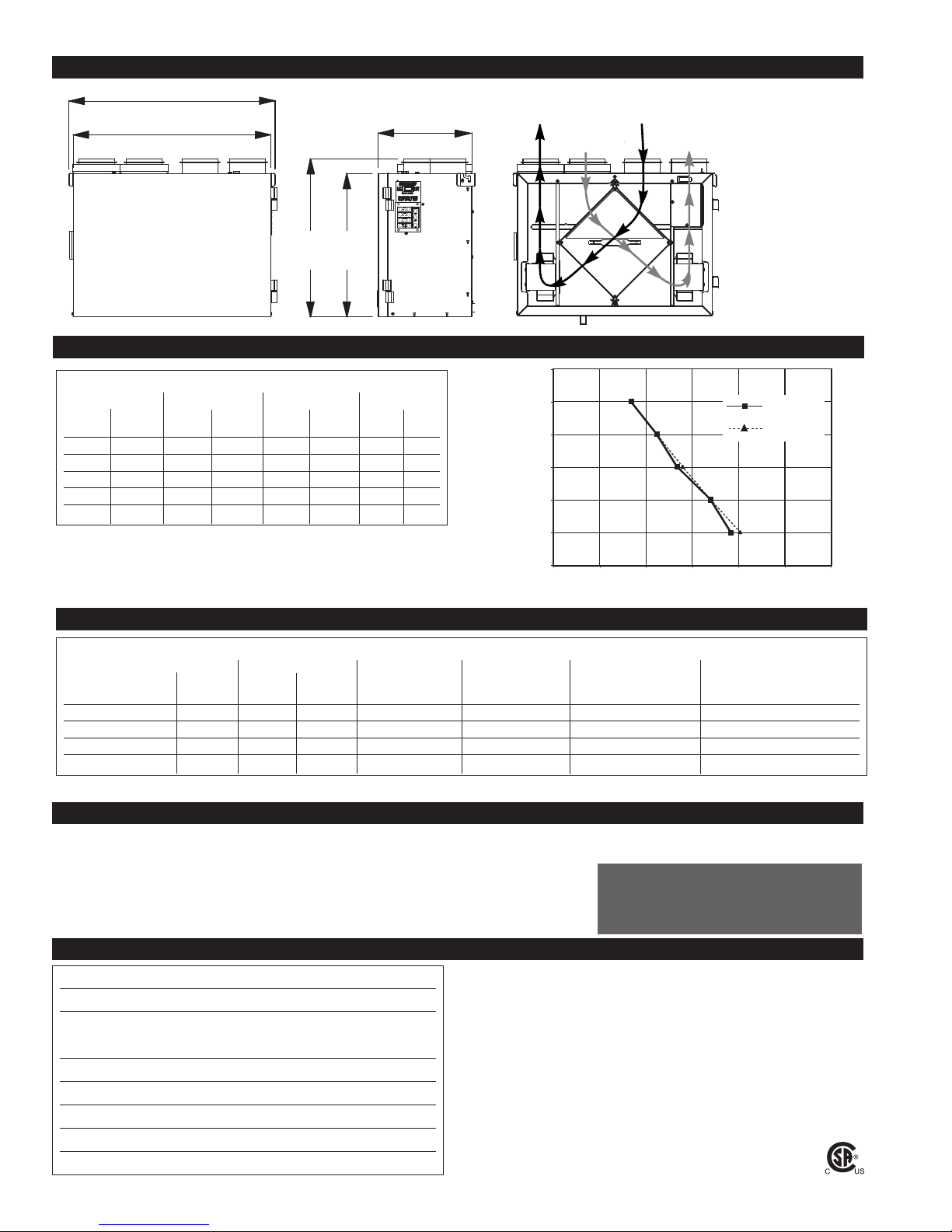
Dimensions & Airflow
0
0.1
0.2
0.3
0.4
0.5
0.6
0 25 50 75 100125 150
cfm (l/s = n x 0.47)
in w.g. (Pa = n x 248)
N
et Supply
Net Exhaust
22.50"
(572mm)
21.50"
(546mm)
-
Ventilation Performance
All units feature three foot plug-in power cord with 3-prong plug.
17.20"
(436mm)
15.60"
(396mm)
10.20"
(259mm)
Stale Air
To Outside
From Outside
From Inside
Fresh Air
Stale Air
Fresh Air
To Outside
• Continuous ventilation
mode of supply and
exhaust airstreams
10˝ (254mm) of clear-
•
ance is recommended
for removal of core
EXT. STATIC
PRESSURE
NET SUPPLY
AIR FLOW
GROSS AIR FLOW
SUPPLY EXHAUST
Pa in wg L/s cfm L/s cfm L/s cfm
25 0.1 45 96 47 99 49 104
50 0.2 40 85 41 88 41 88
75 0.3 32 67 33 69 34 72
100 0.4 26 56 27 58 28 58
125 0.5 20 42 20 43 20 43
Energy Performance
SUPPLY
TEMPERATURE
NET
AIRFLOW
˚C ˚F L/s cfm
POWER
CONSUMED
WATTS
Heating 0 32 26 55 36 57 67 –
0 32 32 68 40 55 63 –
0 32 39 83 40 54 60 –
-25 -13 34 72 35 53 66 –
SENSIBLE
RECOVERY
EFFICIENCY
APPARENT
SENSIBLE EFFEC-
TIVENESS
RECOVERY/MOISTURE
TRANSFER
Specifications and Ratings
• Model: PHRV96
• Total assembled weight: 26 lbs (12kg)
• Cabinet: 24 ga. steel w/powder coat finish
• Motors: ebm motors w/backward curved blades
• Filters: 2 washable electrostatic filters
8.5" (216mm) x 8" (205mm) x 0.125" (3mm)
• Insulated with 1" (25 mm) aluminum foil-face
high density polystyrene foam to prevent
condensation and meet the requirements of
the UL 94HF.
• Core: Aluminum
8.5˝ (216mm) x 8.5˝ (216mm) x 8˝ (205mm)
• Supply & exhaust ducts: 4˝ (100mm)
• Mounting: Wall bracket included
• Electrical requirements:
Volts Frequency Amps Watts
115V
60Hz
3' plug-in power cor
0.36A 40W
d w/ 3-prong plug
LATENT
Contacts
Submitted by: Date:
Qty: Model #:
Comments:
Project #:
Location:
Architect:
Engineer:
Contractor:
4
INSTALLATION
PRACTICAL TIPS
• Install the unit close to the outside
wall on which the supply and
exhaust hoods will be mounted.
• Have a nearby power supply 120
Volts, 60Hz. (power cord is 3
feet long)
• Mount the unit as level as
possible in order to allow proper
condensate drainage.
LOCATION
The HRV must be located in a heated space where it will be possible to conveniently service the unit. Typically the HRV
ould be located in the mechanical room or an area close to the outside wall where the weatherhoods will be mounted.
w
If a basement area is not convenient or does not exist, a utility room or laundry or closet may be used.
Attic installations are not normally recommended due to:
Connecting the following appliances to the HRV
These appliance may cause lint, dust or grease to collect in the HRV , damaging the unit.
NOTE: Connecting any of these type of appliances to the HRV will invalidate your warranty
- the complexity of work to install
- freezing conditions in the attic
- difficulty of access for service and cleaning
clothes dryer
-
- range top
- stovetop fan
- central vacuum system
is not recommended,
including:
• Have access to a water drain for
the condensate of the unit during
defrost.
• Have a certain amount of heat
around the unit (attic installation
is not recommended).
• Installations close to the living
space, such as closets, should be
design and to minimize noise or
vibration transfers.
• Have access for future
maintenance. (10” is
recommended for removal of core)
ELECTRICAL
3 prong plug-in power card.
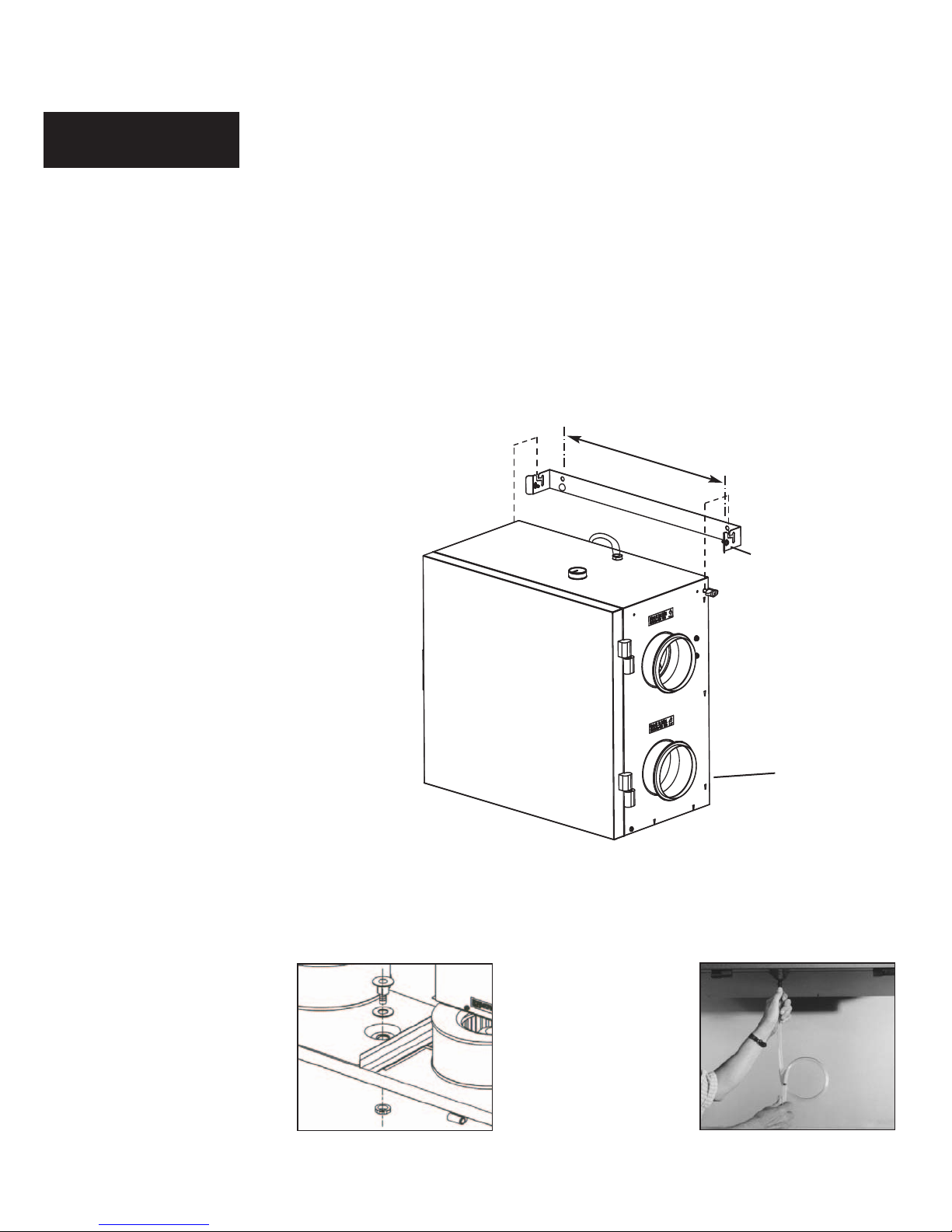
MOUNTING - EASY WALL MOUNT
Attach bracket to wall, lift unit
(26 lbs (12 kg) PHR
nuts into slots on bracket, tighten
ews to secure unit to bracket.
scr
Insert the safety screws & place
wall bumpers to level off the unit.
V96) & slide
16”
(406mm)
Safety screws (included)
Place bumpers on back
of unit (included)
INSTALLING DRAIN LINE - Drainline not included in kit
Through normal operation and during its defrost mode, the HRV may produce some condensation. This water should
flow into a nearby drain, or be taken away by a condensate pump. The HRV and all condensate lines must be installed in
a space where the temperature is maintained above the freezing point. A “P” trap should be made in the drain line. This
will prevent odors from being drawn back up into the unit.
1 Install the drain nipple.
2 Install the drain hose,
making a “P” trap
5
 Loading...