

Diplomat ADEPT DA 270, ADEPT DA 280, ADEPT DA 370, ADEPT DA 380 Instructions For Use Manual
DIPLOMAT DENTAL s.r.o.
Vrbovská cesta 17
921 01 Piešťany
SLOVAKIA
INSTRUCTIONS FOR USE
Dental units
DIPLOMAT ADEPT DA 270, DA 280
DIPLOMAT ADEPT DA 370, DA 380

INSTRUCTIONS FOR USE DA 270, DA 370, DA 280, DA 380
UM_EN_DA270_DA280_DA370_DA380_m2015_2019-04_ver1.9 2 / 67
CONTENTS
1 PURPOSE AND USE ........................................................................................................................................ 3
2 PRODUCT DESCRIPTION ............................................................................................................................... 4
3 TECHNICAL DATA ........................................................................................................................................... 5
3.1 Technical parameters ......................................................................................................................................... 5
3.2 Used Symbols .................................................................................................................................................... 5
4 MAIN PARTS OF THE DENTAL UNIT ............................................................................................................. 6
4.1 Production label of dental unit ............................................................................................................................ 8
5 PRE-INSTALLATION REQUIREMENTS.......................................................................................................... 9
5.1 Requirements for the installation of media ......................................................................................................... 9
5.2 Electrical Requirements .................................................................................................................................... 10
5.3 Unit operational requirements .......................................................................................................................... 10
6 ASSEMBLY AND INSTALLATION ................................................................................................................ 11
7 PUTTING THE UNIT INTO OPERATION ....................................................................................................... 12
8 PRODUCT OPERATION ................................................................................................................................ 14
8.1 Control panel with instruments ......................................................................................................................... 14
8.1.1 Main screen ...................................................................................................................................................... 14
8.1.2 Ways of changing parameters in individual screens ........................................................................................ 18
8.1.3 Setting of the water amount.............................................................................................................................. 29
8.1.4 Button of the brake of the control panel (according to the version) ................................................................. 29
8.1.5 Operation of individual instruments .................................................................................................................. 30
8.1.6 Syringe.............................................................................................................................................................. 31
8.1.7 Turbine.............................................................................................................................................................. 31
8.1.8 Micromotor BLDC - DX, DX BLUE, DX PRO .................................................................................................. 35
8.1.9 Surgical micromotor DX SRG with peristaltic pump ........................................................................................ 39
8.1.10 Scaler ................................................................................................................................................................ 42
8.2 Foot controller ................................................................................................................................................... 45
8.3 Spittoon block ................................................................................................................................................... 49
8.3.1 Assistant control panel ..................................................................................................................................... 50
8.3.2 Simple assistant tables ..................................................................................................................................... 50
8.3.3 Equipment of the spittoon block ....................................................................................................................... 50
8.4 Dental operating light ........................................................................................................................................ 51
8.5 Cart (only for DA 280, DA 380 – CART) .......................................................................................................... 51
8.6 Hygiene............................................................................................................................................................. 52
8.7 Manual control of the head rest ........................................................................................................................ 52
8.8 Manual control of the right arm rest .................................................................................................................. 52
8.9 Completion of work ........................................................................................................................................... 53
9 PRODUCT MAINTENANCE ........................................................................................................................... 54
10 CLEANING, DISINFECTION AND DECONTAMINATION ............................................................................ 55
10.1 Disinfection of the cooling waterlines of instruments ....................................................................................... 55
10.2 Semi-automatic disinfection of the cooling waterlines of instruments (optional) .............................................. 55
10.3 Cleaning and decontamination of the saliva ejector ......................................................................................... 58
10.4 Cleaning and decontamination of the big and small aspirator ......................................................................... 58
10.5 Cleaning of the sieve of the separation block................................................................................................... 58
10.6 Cleaning and Disinfection of Dürr spittoon valve on wet suction system ......................................................... 59
10.7 Cleaning and decontamination of the spittoon block ........................................................................................ 60
10.8 Cleaning, disinfection and decontamination of other parts of the dental unit ................................................... 61
11 DISPOSAL OF EQUIPMENT .......................................................................................................................... 62
12 SERVICING THE UNIT ................................................................................................................................... 62
13 GUARANTEE .................................................................................................................................................. 62
14 CONTENTS OF THE PACKAGING ................................................................................................................ 63
15 TRANSPORTATION CONDITIONS ............................................................................................................... 63
16 STORAGE CONDITIONS ............................................................................................................................... 63
17 REQUIREMENTS ON ELECTROMAGNETIC COMPATIBILITY ACCORDING TO EN 60601-1-2.............. 64
18 TABLE OF INSTRUMENTS EQUIPMENT ..................................................................................................... 67
INSTRUCTIONS FOR USE DA 270, DA 370, DA 280, DA 380
UM_EN_DA270_DA280_DA370_DA380_m2015_2019-04_ver1.9 3 / 67
1 PURPOSE AND USE
These Instructions for Use describe how to use the dental units of DIPLOMAT ADEPT
DA 270, DA 370 and DA 280, DA 380. Please read these Instructions for use thoroughly before attempting to
use them.
Intended purpose of use of the dental unit: Equipment, used alone or in combination with instrumentation, intended to be
used for prevention, treatment or allevation of an illness in the area of oral cavity of the patient. It is an integral part of dental
equipment formed by a set of interconnected subassemblies of dental equipment and instruments, forming a functional unit
for dental treatment. v oblasti ústnej dutiny pacienta.
Please read these Instructions for Use thoroughly before attempting to use the unit. The dental unit is allowed to be operated
only by the dentist who has been made familiar with the present Instructions for Use and the dental applications that can
be done by means of the dental unit in question. In order for you to be satisfied with the dental unit, the following must be
observed: Installation, setting and/or modification must be made by the qualified authorized service personnel of an
organization that has a licence for such activity. Conditions for the use of media and installation given in the Instructions
for Use of DIPLOMAT ADEPT DA 270, DA 370 and DA 280, DA 380 must be met, too.
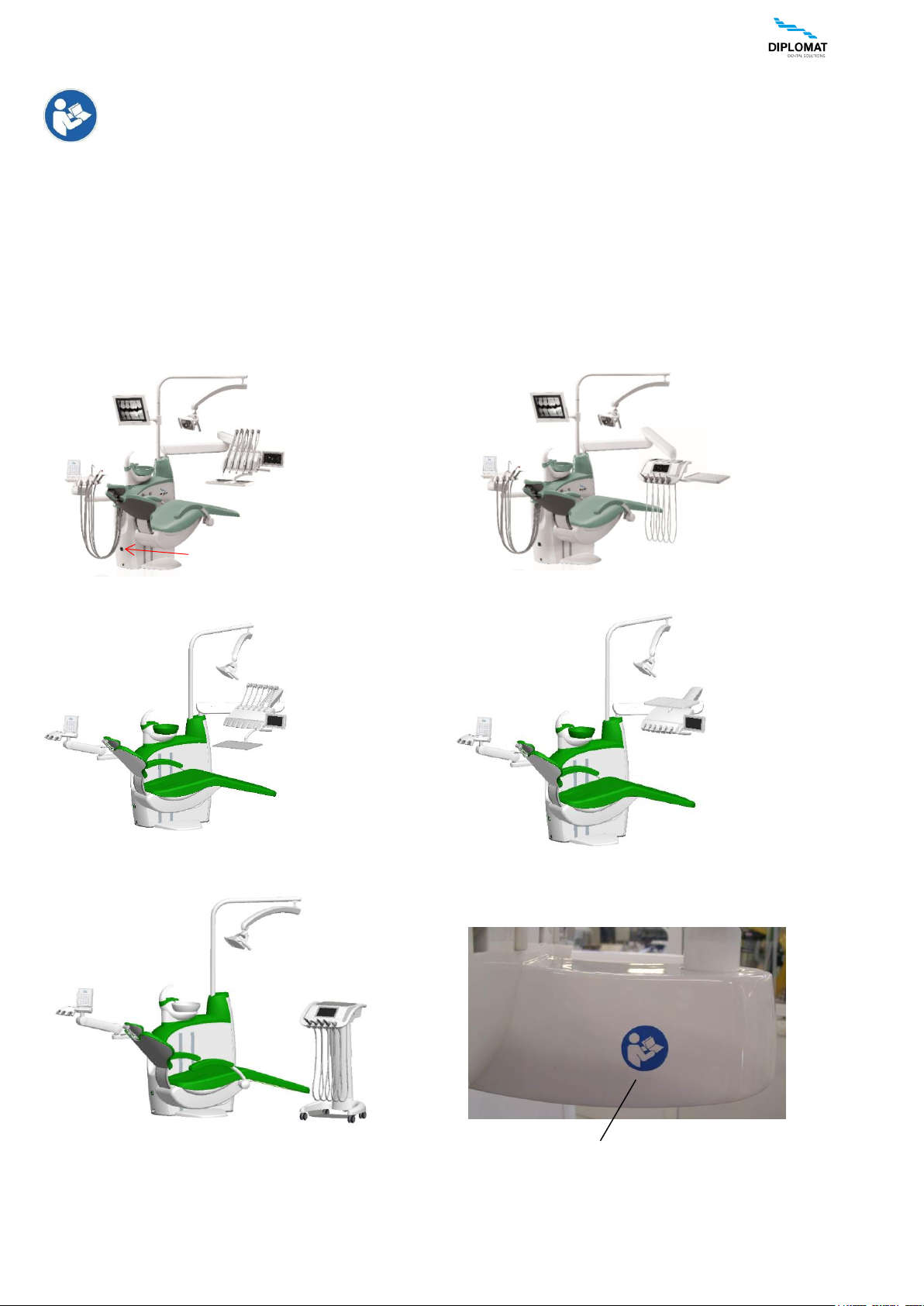
DIPLOMAT ADEPT DA 280
DIPLOMAT ADEPT DA 270
DIPLOMAT ADEPT DA 370
DIPLOMAT ADEPT DA 380
DIPLOMAT ADEPT DA 280, DA 380 CART
Safety symbol
Main power switch
INSTRUCTIONS FOR USE DA 270, DA 370, DA 280, DA 380
UM_EN_DA270_DA280_DA370_DA380_m2015_2019-04_ver1.9 4 / 67
2 PRODUCT DESCRIPTION
The dental unit of DIPLOMAT ADEPT DA 270, DA 370 is designed as a stationary unit with a carried chair and upper hose
delivery and DIPLOMAT ADEPT DA 280, DA 380 with lower hose delivery, while DA 280, DA 380 is available also in CART
version. Control panel pantograph with the control panel with touch display and instruments, and light pantograph with the
dental operating light are fitted at the upper part of the bearing pillar of the spittoon block. In DA 280, DA 380 CART version
is used the control panel with lower hose delivery, placed on a cart.
The instruments are controlled by the foot controller, except for the syringe, big and small aspirator, saliva ejector (and/or
curing lamp and intraoral camera). The handle serves for re-positioning of the control panel. The spittoon block is delivered
in various versions with a saliva ejector or with an assistant arm with big and small aspirator. The spittoon bowl and and the
bowl flushing tube are detachable. The bowl drive is either manual or powered (according to the requirements). Suction
handpieces of the big and small aspirator are detachable, capable of being disinfected and sterilized. Handpieces of the
saliva ejector are for single use. Side table with a side dish fixed to the arm of the light pantograp and monitor arm with LCD
monitor are installed as an option upon order. The dental unit of DIPLOMAT ADEPT DA 270, DA 370 , DA 280, DA 380 is
always equipped on the control panel with a syringe.
The control panel can be fitted with the following instruments:
Condition
Remark
minimum 1 syringe
max. 4 rotary instruments
DA270, DA280
max. 5 rotary instruments
DA370, DA380
max. 3 turbines with light
max. 3 BLDC micromotors with light
max. 3 x DX
max. 3 x DX BLUE
max. 2 x DX PRO + 1 x SRG
max. 2 x DX PRO BLUE + 1 x SRG
1 scaler
USS – Ultra Sonic Scaler
1 curing lamp
LED
For optional and supplementary equipment, see the current price list
In the manual are used following shortcuts:
USS - ultrasonic scaler (calculus remover)
PLM - curing lamp
BLDC motor – brushless motor
Parts of the dental unit coming into contact with the patient:
• Seat
• Backrest
• Headrest
• Handrest
• Small and big aspirator
• Saliva ejector
• Instruments located on the control panel
INSTRUCTIONS FOR USE DA 270, DA 370, DA 280, DA 380
UM_EN_DA270_DA280_DA370_DA380_m2015_2019-04_ver1.9 5 / 67
3 TECHNICAL DATA
3.1 Technical parameters
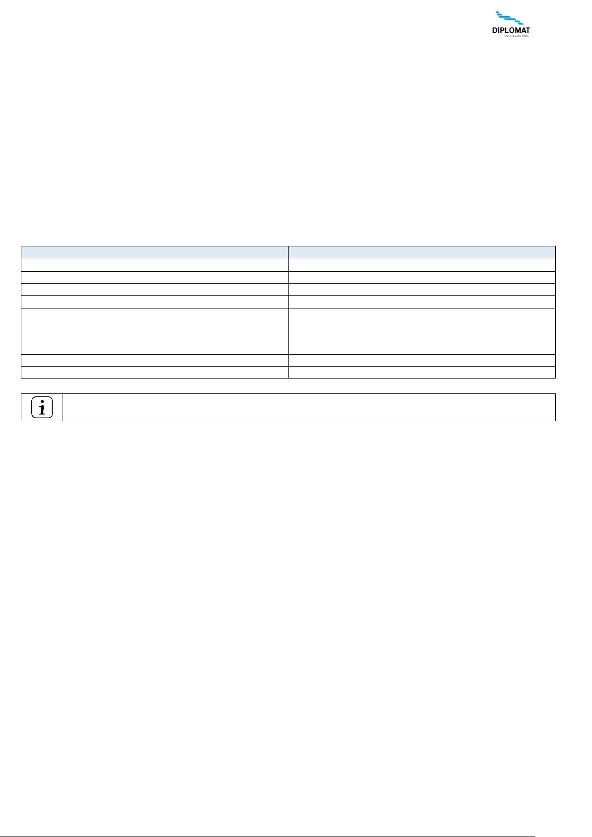
Dental unit
Values
Supply voltage
230V ± 10%
Frequency
50 Hz ± 2 %
Max. power consumption
1900 VA + 10%
Input pressure of air
from 0,45 to 0,8 MPa
Input pressure of water
from 0,3 to 0,6 MPa
Dental unit netto weight
145 kg + max. 20 kg according to version
Dental unit brutto weight
210 kg + max. 35 kg according to version
Type of protection against electric shock
Class I equipment
Degree of protection against electric shock
applied parts of B type
Degree of protection by cover
IP21
Temperature of water for the cup
35 ± 5 °C (with heater fitted)
Max. recommended load of light arm tray table
1,5 kg
Max. recommended load of dentist’s panel tray table:
• for stainless plate 180x280 mm
• for stainless plate 290x370 mm
0,5 kg
1,5 kg
Type of operation
continuous with intermittent loading, corresponding to the
common dental practice.
Chair
Values
Range of the height of the seat above the floor
385 mm – 825 mm 15 mm (DA270,DA280)
320 mm – 825 mm 15 mm (DA370,DA380)
Range of the tilting of the backrest from vertical plane
20° 2° to 90° 2° (DA270,DA280)
13° 2° to 97° 2° (DA370,DA380)
Range of the tilting of the seat from horizontal plane
3° to 21° 2° (DA370,DA380)
Chair vertical movement time (from min. to max.)
maximum 20 seconds
Backrest movement time (from min. to max.)
maximum 18 seconds
Seat tilt duration
maximum 8 seconds
Loading capacity of the chair (EN ISO 7494-1)
maximum 200 kg
Chair weight netto DA270,DA280
60kg + max. 5 kg according to version
Chair weight brutto DA270,DA280
110 kg + max. 20 kg according to version
Chair weight netto DA370,DA380
65kg + max. 5 kg according to version
Chair weight brutto DA370,DA380
115 kg + max. 20 kg according to version
Operation mode
1 : 16 (cycle e.g. 25sec. run, 400sec. rest)
Noise level of the chair
maximum 54 dB
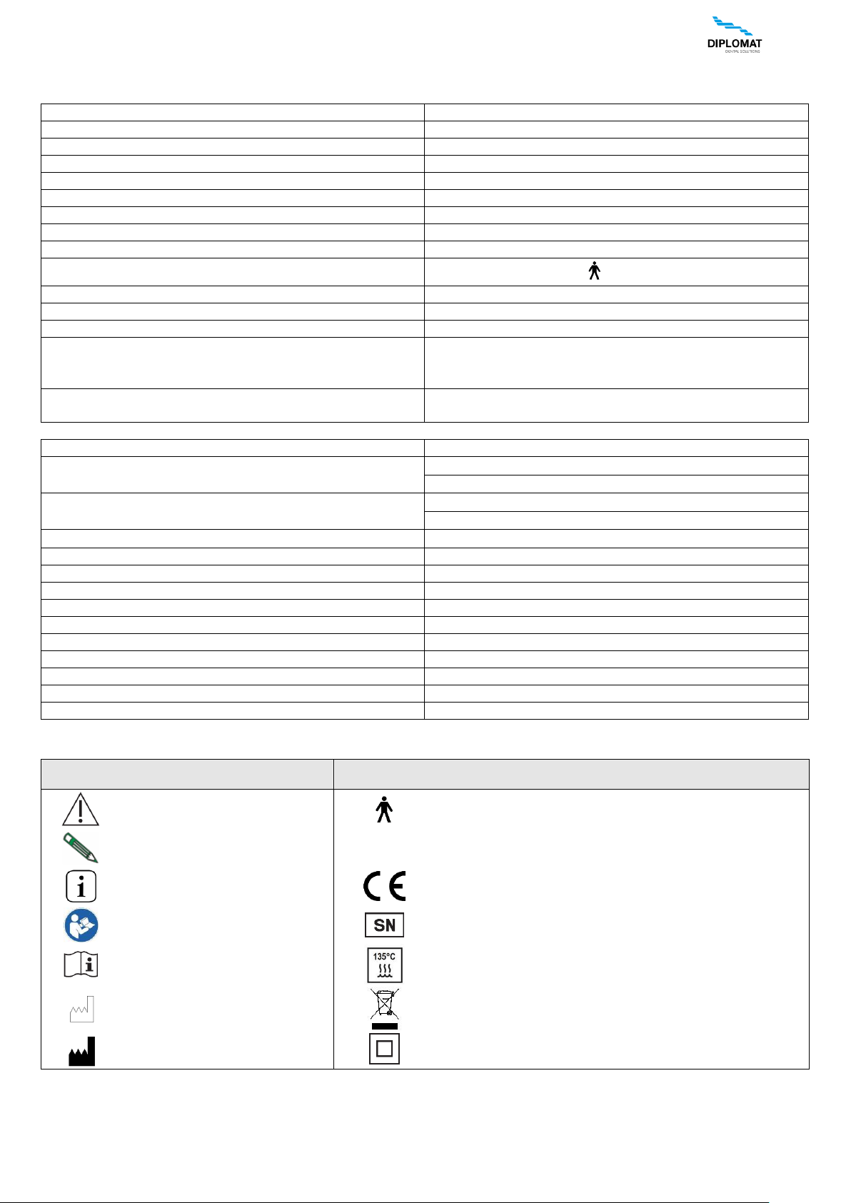
3.2 Used Symbols
Symbol
Description
Symbol
Description
Warning, Caution
Type B applied part
Note
IP21
Protection against vertically falling drops of water e.g.
condensation
Additional information
Mandatory conformity marking for certain products sold
within the European Economic Area
Refer to instruction manual
Serial number, production number
See the instruction manual
Sterilizable in a steam sterilizer (autoclave) at
temperature specified
Production date
Device is among the dangerous wastes - hand them
over in the collection yard
Manufacturer
Class II Equipment
INSTRUCTIONS FOR USE DA 270, DA 370, DA 280, DA 380
UM_EN_DA270_DA280_DA370_DA380_m2015_2019-04_ver1.9 6 / 67
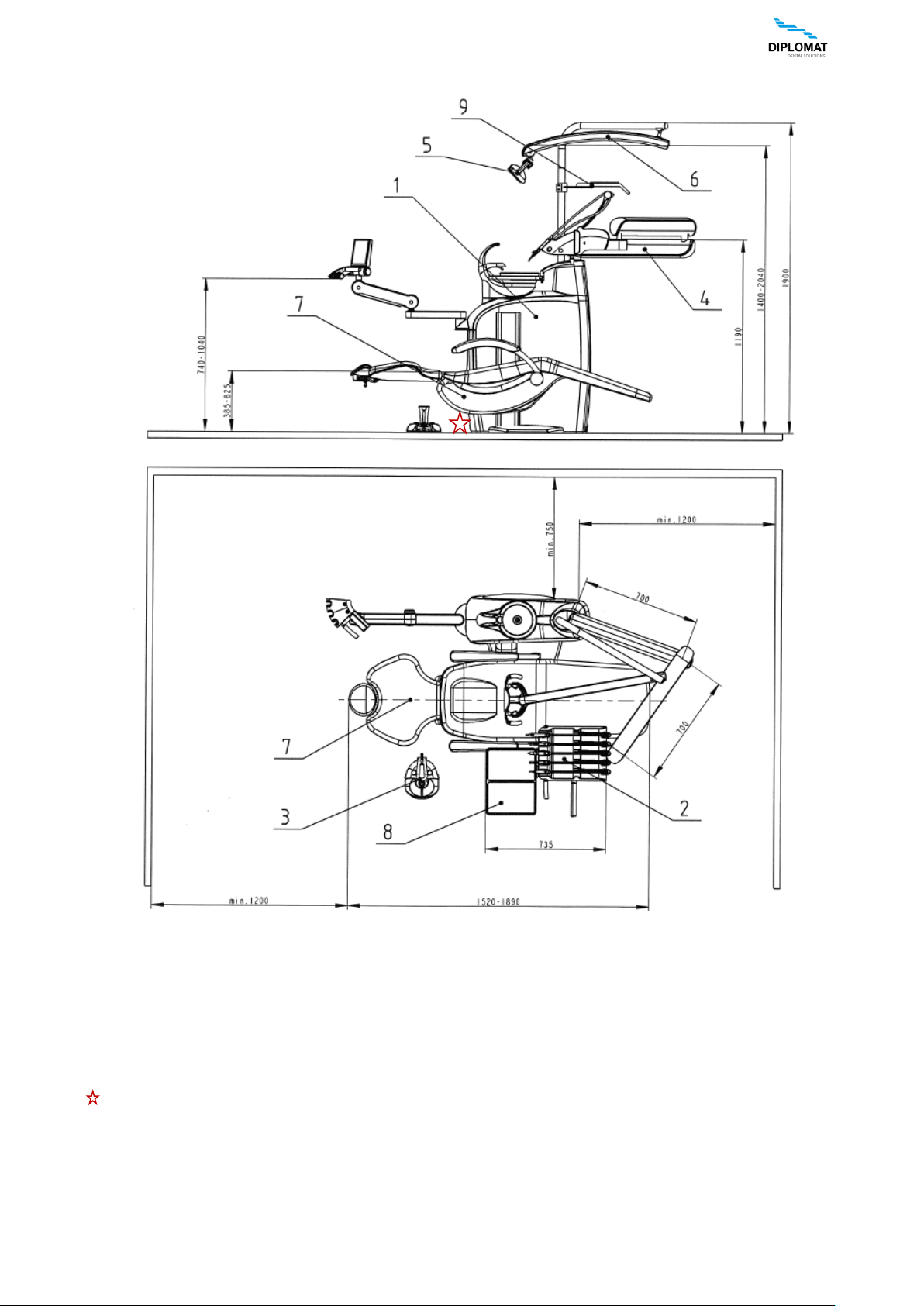
4 MAIN PARTS OF THE DENTAL UNIT
1. Spittoon block with assistant arm
2. Control panel (5 – tools at DA 270, DA 280 and 6 – tools at DA 370, DA 380)
3. Foot controller
4. Pantograph of the control panel
5. Dental operating light
6. Pantograph of the light
7. Dental chair
8. Tray table
9. Side table
Main switch is located on the outer side of the spitton block
INSTRUCTIONS FOR USE DA 270, DA 370, DA 280, DA 380
UM_EN_DA270_DA280_DA370_DA380_m2015_2019-04_ver1.9 7 / 67
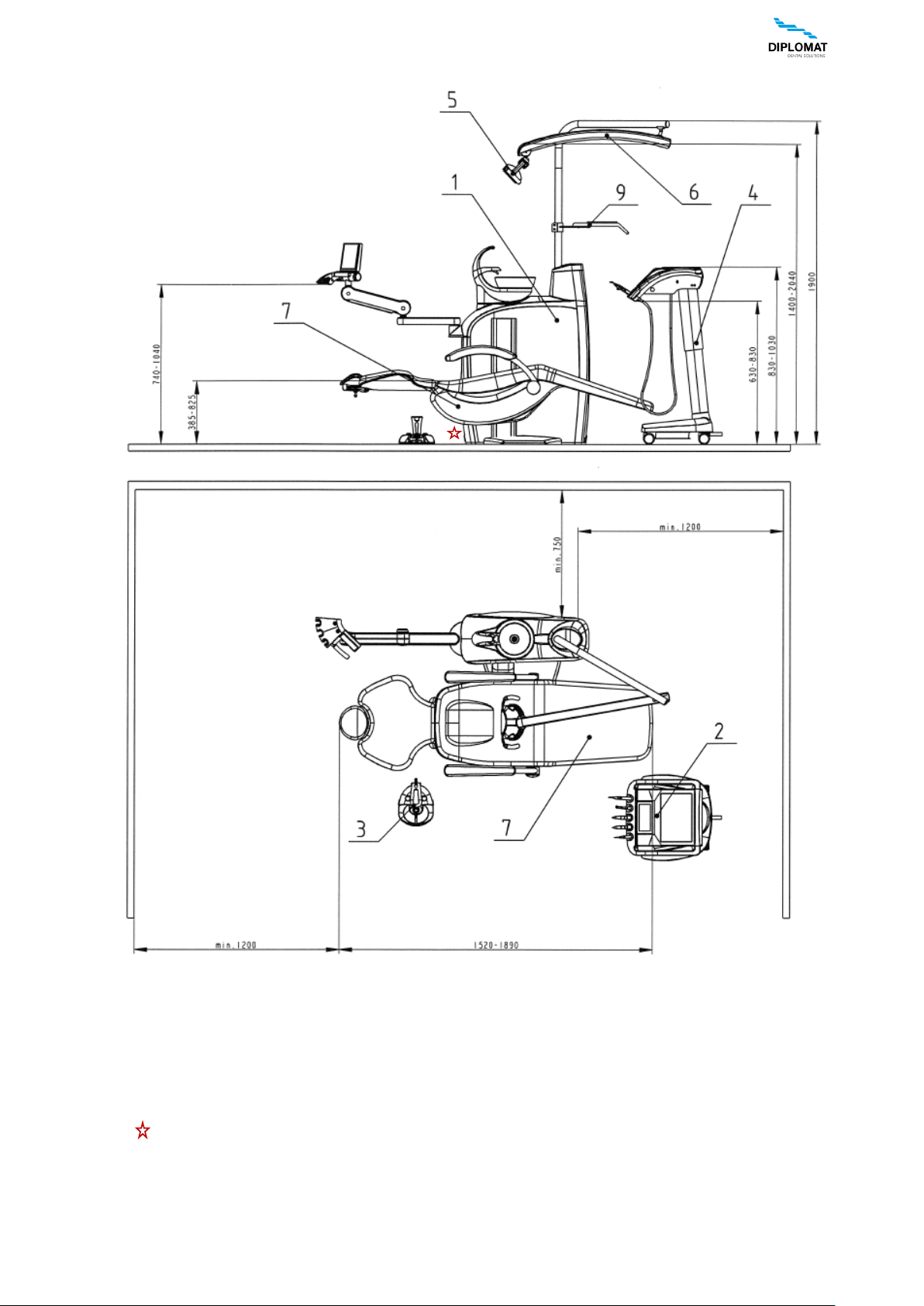
MAIN PARTS OF THE DENTAL UNIT DA 280, DA 380 CART
1. Spittoon block with assistant arm
2. Control panel (5 – tools at DA 280 and 6 – tools at DA 380 )
3. Foot controller
4. CART
5. Dental operating light
6. Pantograph of the light
7. Dental chair
9. Side table
Main switch is located on the outer side of the spitton block
INSTRUCTIONS FOR USE DA 270, DA 370, DA 280, DA 380
UM_EN_DA270_DA280_DA370_DA380_m2015_2019-04_ver1.9 8 / 67
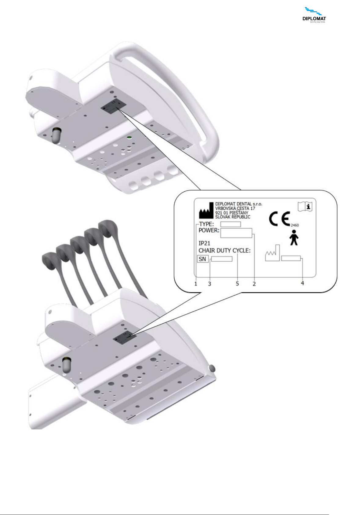
4.1 Production label of dental unit
Legend:
1. designation of the unit type
2. basic electrical parameters
3. serial number
4. production date
5. chair operation mode
INSTRUCTIONS FOR USE DA 270, DA 370, DA 280, DA 380
UM_EN_DA270_DA280_DA370_DA380_m2015_2019-04_ver1.9 9 / 67
5 PRE-INSTALLATION REQUIREMENTS
Warning
Pre-installation and installation must be performed according to the applicable standards of the particular
country and in accordance with the valid documentation of the manufacturer, which is owned by each
authorized representative of DIPLOMAT DENTAL s.r.o.
Do not install in premises with a potential explosion hazard!
Caution
To avoid the risk of electric shock, device must be connected to the power supply with a protective earthing
Do not modify this device without prior authorization of the manufacturer.
5.1 Requirements for the installation of media
Floor
The floor must have a concrete foundation of at least 100 mm thickness. The slope of the floor must not exceed 1%. The
use of antistatic floor is recommended.
Water
Drinkable water with input pressure of 0,3 MPa to 0,6 MPa with the flowrate of min.4 l/min., without particles bigger than
50 µm, which might clog the small cross sections of the pipes of the dental unit, must be used. If the water contains particles
bigger than 50 µm, there must be introduced 50 µm advance filter/strainer.
The water hardness must be less than 2,14 mmol/l.
The pH must be in the range of 6,5 to 8,5.
Maximal electrical conductivity of the water shall not exceed 2000 µS/cm.
Water must comply with the local regulations for drinking water.
Tubes made of Cu and/or PE are recommended.
Cooling of instruments using water from the central distribution
In the unit's central water distribution, there is included a shut-off valve and the valve to prevent reverse flow of water.
Requirements and recommendations:
• If the central water is used for cooling of dental instruments, then it is necessary to install particle filter with precision
of 5 µm before the water enters dental unit.
• Hard water can lead to dysfunction of the dental unit.
If the water contains more than 50 mg of CaO/l or 36 mg of MgO/l, then it is necessary to include water softener
device (for adjusting the hardness of the water) connected at the input of the water distribution.
This water treatment device is required in case when distilled water is not used.
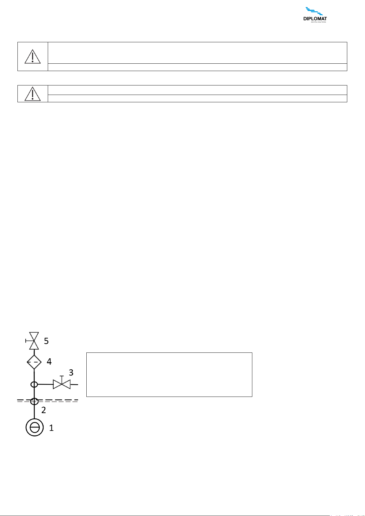
• When there is a requirement to install the mount point for the sampling input water, the following diagram shows the
recommended location mount point for the sampling input water.
The said devices are not integral parts of the dental unit.
Connection diagram of input elements in dental unit (STN EN ISO 7494-2)
1 - Input water from an external water supply
2 - Mount point of inlet water
3 - Mount point for taking the samples of the input water
4 - Filter of water particles
5 - Manual shut-off valve
INSTRUCTIONS FOR USE DA 270, DA 370, DA 280, DA 380
UM_EN_DA270_DA280_DA370_DA380_m2015_2019-04_ver1.9 10 / 67
Air
Supply of at least 55 l/min. of air at the pressure of 0,45 až 0,8 MPa, oilless, clean and dry must be ensured. Recommended
values for moisture limit (dew point not more than -20 ° C at atmospheric pressure), oil pollution limit (Max. 0.5 mg/m3),
limit of pollution for particles (no more than 100 particles per cubic meter for particles sizes of 1 µm to 5 µm).
Suction (in the event of the version of the spittoon block with big and small aspirator)
Static vacuum must be within the range of min. 0,005 MPa (50 mbar) to max. 0,02 MPa (200 mbar), measured at installed
position. When the static vacuum is higher than 0,02 MPa, a suction calibration (regulating) valve should be introduced in
the suction branch to restrict the max. vacuum to 0,02 MPa. The said regulating valve does not form an integral part of the
dental unit. The suction unit must produce the flowrate of at least 450 l/min., measured at the installed position.
Waste
The waste /drain/ branch must have continuous slope of min. 1% with minimum flowrate of 10 l/min. and must be free of
sharp bends and conditions that might cause backlow. Do not use the same waste branch with another dental unit or
a basin! It is allowed to use tubes made of polypropylene or cured polyethylene.
Note
If the regulations of the country in which the installation is carried out require an amalgam catcher, the dental
unit with the spittoon block without the amalgam catcher must be connected to an external amalgam catcher.
Installation of the external amalgam catcher must be carried out according to the instructions of its
manufacturer.
5.2 Electrical Requirements
Recommended mains fuse rating
Recommended rating of the fuse of the supply main is 16A (in the event of circuit breaker – circuit breaker with switchingoff characteristic of C type). No other items of equipment should be connected to the supply main in question!
Maximum power input of the dental unit is 1550 VA. The supply main must comply with the respective national standard.
Recommendation
Unless the national standard stipulates otherwise, the manufacturer recommends to use current protective switch with the
sensitivity of 30mA and instantaneous time of switching-off.
Pre-installation requirement having been met, assembly and installation of the dental unit is carried out and it is connected
to the media.
Mutual interference
Dental unit during its operation does not affect the operation of other electronic devices near it
5.3 Unit operational requirements
Parameter
Value from
Value to
Ambient temperature range
+15 °C
+40 °C
Relative humidity range
30%
75 % non-condensing humidity
Atmospheric pressure range
700 hPa
1060 hPa
Altitude
≤ 3000 m
INSTRUCTIONS FOR USE DA 270, DA 370, DA 280, DA 380
UM_EN_DA270_DA280_DA370_DA380_m2015_2019-04_ver1.9 11 / 67
6 ASSEMBLY AND INSTALLATION
The installation must be carried only by the service technician with a valid certificate, otherwise will not be
recognized by any warranty. The registration form must be written out and sent to the manufacturer or seller
Unpacking of the unit and inspection of the delivery
Inspect the transport packages for damage. If a defect of the transport package is found, do not open the consignment
and report the defect to the forwarding agent or seller immediately. If the consignment is intact, carefully open the
package and unpack individual parts of the dental unit. Check the completness of the delivery according to the Packing
list. If the unit is equipped with a touch keyboard, take care of its glass surface in handling.
Workload of dentist's control panel arm
Except for common handling with the dentist control panel and permissible loading of the tray table, the
pantographic arm of the control panel must not be loaded by persons or articles leaning against it,
suspension of persons or articles or by other similar manners
In the case of the installation of the base (installation) plate, we recommend to isolate the installation plate
around its perimeter by transparent silicone sealant against the floor.
When not isolated with a silicone sealant, it may occur damage of the product, caused by the influence of
water and cleaning detergents, for which the manufacturer might not recognize any complaint.
Sieves (packed with small parts) are to be inserted in the tips of the aspirators
INSTRUCTIONS FOR USE DA 270, DA 370, DA 280, DA 380
UM_EN_DA270_DA280_DA370_DA380_m2015_2019-04_ver1.9 12 / 67
7 PUTTING THE UNIT INTO OPERATION
Warning
Disinfection of new dental unit before its first use
Before putting the unit into operation, your technician must carry out disinfection of waterlines of
instruments, according to instructions in Installation manual.
• switch on the compressor and let it get pressurized with air
• open the central water supply
• turn on the suction unit
• check the instruments for their positions
• turn on the main switch
the indicator light of the main switch goes on and the following initial screen is displayed briefly:
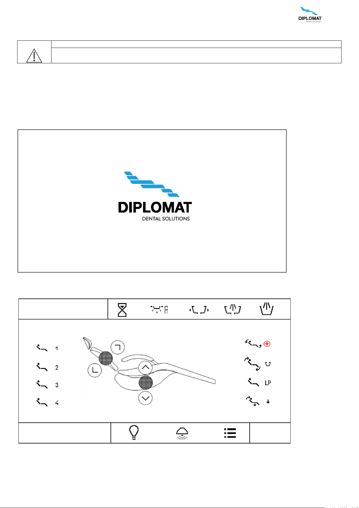
After that the main screen is displayed:
for units: DA270/DA280
12.AUG 12:12
DR.SMITH
TYPE
INSTRUCTIONS FOR USE DA 270, DA 370, DA 280, DA 380
UM_EN_DA270_DA280_DA370_DA380_m2015_2019-04_ver1.9 13 / 67
for units: DA370/DA380
The unit is connected to the distribution of water and air. After audible signal, short-long tone, the unit is ready to
work. If the dental unit is equipped with electrical water heater for cup filler, it is necessary to wait for approx. 10 min. for
the water to be warmed up to the desired tempeerature. In turning the unit on, no instruments should be taken, the foot
controller should be in the rest position and the buttons of the keyboards should not be depressed.
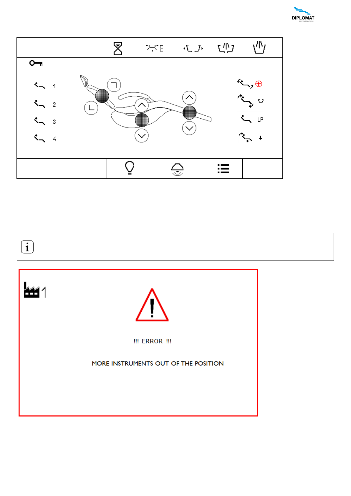
More instruments out of the position
Besides the small and big aspirator, saliva ejector, curing lamp, the syringe on the assistant table and the
syringe on the control panel only one instrument can be used (taken out of the holder) simultaneously.
Not observing of the condition above is indicated on the display by the following message
12.AUG 12:12
DR.SMITH
TYPE
INSTRUCTIONS FOR USE DA 270, DA 370, DA 280, DA 380
UM_EN_DA270_DA280_DA370_DA380_m2015_2019-04_ver1.9 14 / 67
8 PRODUCT OPERATION
8.1 Control panel with instruments
The touch display is legible in each working position of the dentist (both sitting and standing).
8.1.1 Main screen
The main screen is displayed after turning the unit on.
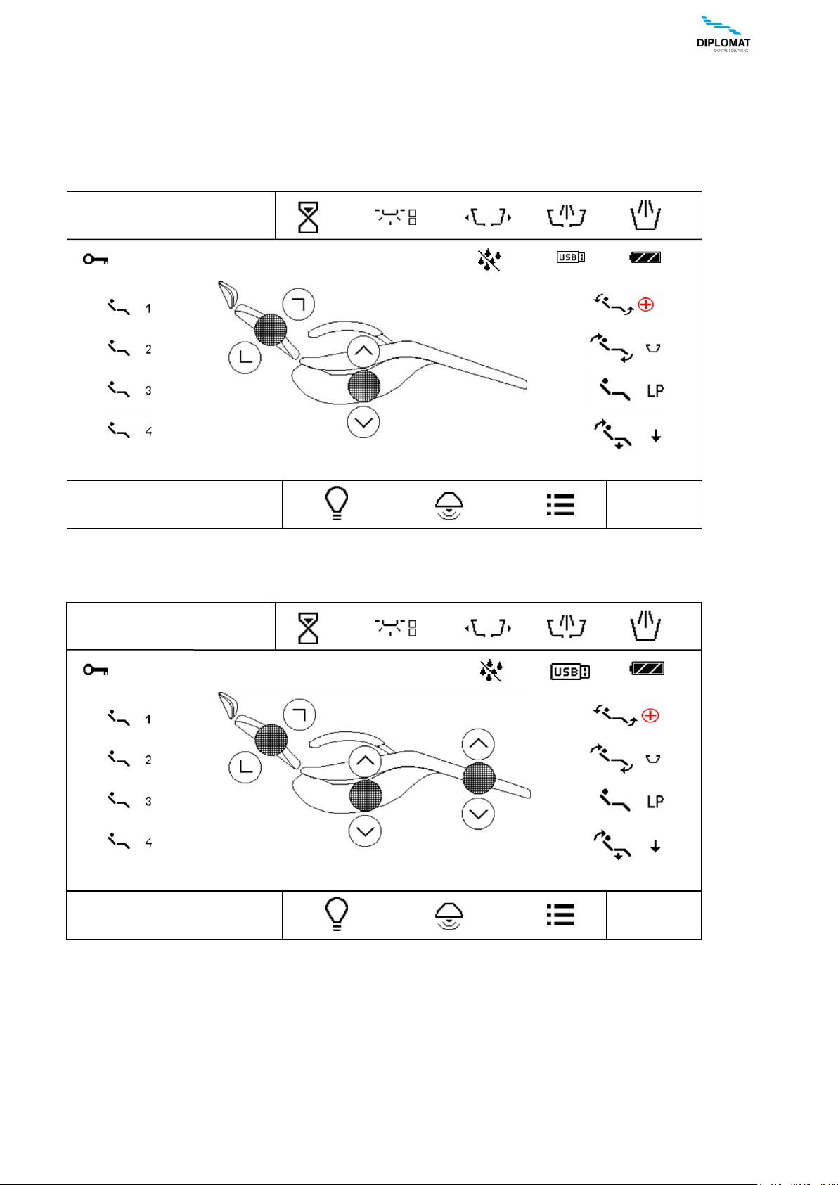
Main screen for DA270 / DA280
Main screen for DA370 / DA380
12.AUG 12:12
DR.SMITH
TYPE
12.AUG 12:12
DR.SMITH
TYPE
INSTRUCTIONS FOR USE DA 270, DA 370, DA 280, DA 380
UM_EN_DA270_DA280_DA370_DA380_m2015_2019-04_ver1.9 15 / 67
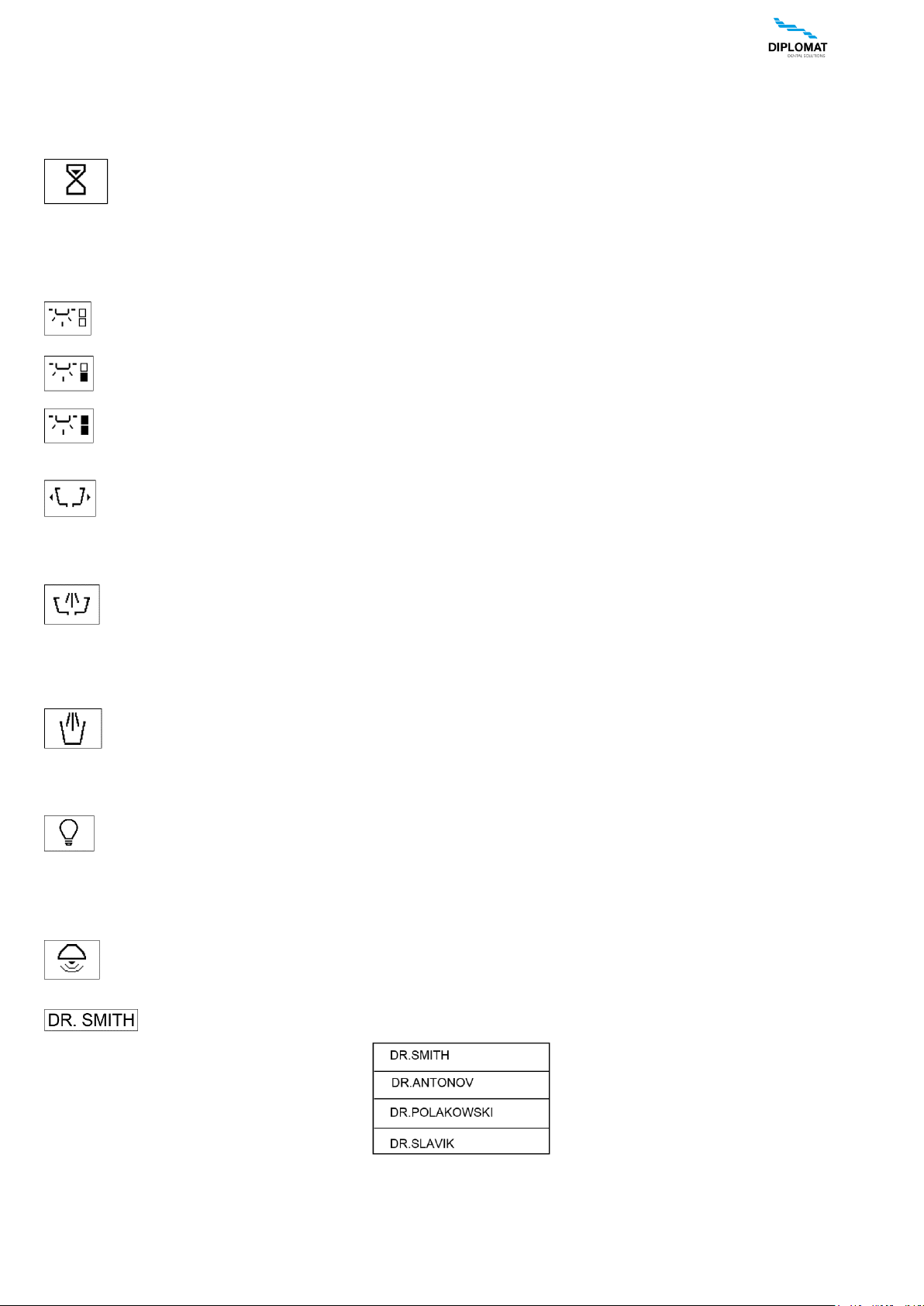
Current time and date
12.AUG 12:12
Time and date can be set in user menu
Alarm
It serves to warn the dentist. It has the function of timer.
The time is adjustable. Press the button to display menu with available times. One of them marked with U can
be set in the user menu. By pressing the button with desired time the time starts to count down to zero value
by 1 second. By repeated pressing of the button during countdown the timer function is cancelled. When the time at
countdown reaches 00:00, an audible signal sounds.
Light
It has three basic level of intensity:
Switched off
Lowered intensity of illumination
for work with photocomposites
Standard intensity
Press the button to alternate between the individual levels of illuminance.
Bowl rotation – to working position, programming.
Press and hold the button for more than 1 second, the bowl will rotate until the button has been released and the
rotation time is saved into the memory automatically. Press the button for less than 1 second to shift the bowl to
programmed position. If the bowl is shifted when the button is pressed, it returns to its starting position. To interrupt
the bowl running, press the button for less than 1 second. (Valid only for the bowl with powered drive).
Bowl flushing
Press and hold the button for more than 2 seconds – the bowl is being flushed until the button has been released
and the flushing time is saved in the memory automatically. To start the flushing for the time saved in the memory,
press the button briefly. To stop the flushing during the flushing time, press the button briefly; the time saved in
the memory is not changed. The flushing starts automatically also after the bowl has returned to zero position. Automatic
starting of bowl flushing can be turned on/off in the user menu.
Cup filling
Press and hold the button for more than 2 seconds – the cup is being filled until the button has been released
and the filling time is saved in the memory automatically. To start the filling for the time saved in the memory,
press the button briefly. To stop the filling during the filling time, press the button briefly; the time saved in the
memory is not changed.
Turning the negatoscope on/off
Press the button to increase brightness of the display backlight to 100%, place the negative and fix it with the
magnetic clip furnished. To cancel the function, press the button again and the brightness will return to previous
level. The negatoscope can be turned on when an instrument is taken.
If a picture is selected from inserted and recognized USB key by means of USB menu, then the said picture is displayed
instead of white background.
Bell
Press and hold the button to switch the relay of the bell in the spittoon block.
User
Displayed information about the current user. Selection of four users is available, i.e. data for four users is
stored in the memory. By pressing the button a pop-up menu is displayed with potential users.
To select the user, press the respective button. User name can be edited in the user menu. After the desired item has
been pressed the display is reset and the parameters are set for the selected user.
INSTRUCTIONS FOR USE DA 270, DA 370, DA 280, DA 380
UM_EN_DA270_DA280_DA370_DA380_m2015_2019-04_ver1.9 16 / 67
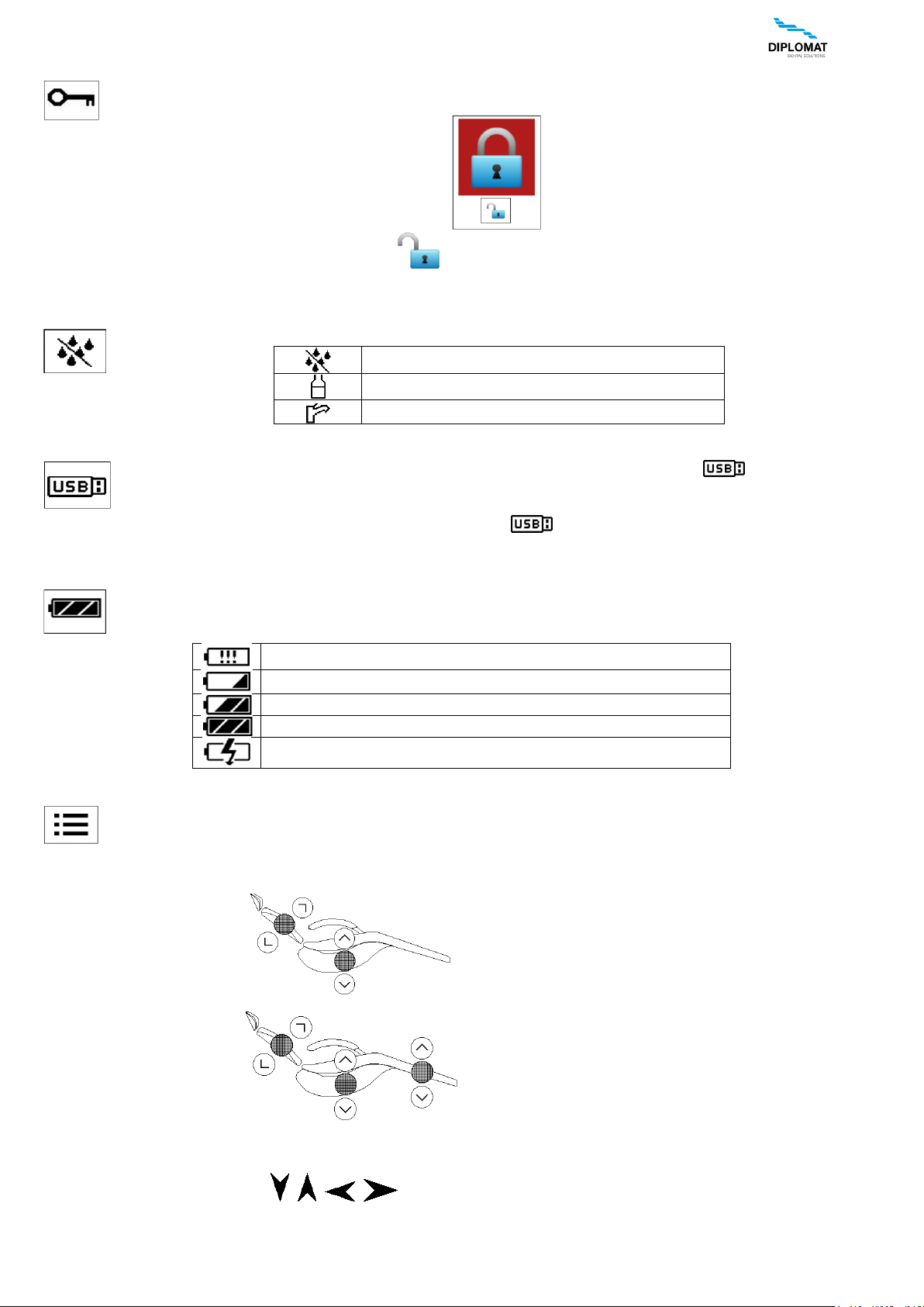
Locking of the keyboard
The keyboard can be „locked“ for cleaning. To block the keyboard, press and hold the button for approx. 3
seconds. The condition is indicated as follows:
To unlock the keyboard, press and hold the button for approx. 3 seconds.
In both cases the waiting interval is indicated with a small bargraph.
Indication of the water source for instruments
Possible statuses depending on the switch position:
No source of water has been chosen
The source is distilled water from the bottle
The source is water from central water system
Indication of USB key /USB flash drive/
After the USB key has been inserted into the USB connector and activated, the icon is displayed on the
main screen. If the icon is not displayed within 5 seconds after the key has been inserted, it means that the
key has not been activated. If that is the case, pull the USB key out and insert it again quickly. If this fails 3
times, then the USB key probably cannot be recognized. If the icon is highlighted, we can work with the USB key
by means of USB menu.
Indication of the accumulator condition in the wireless foot controller
The icon is displayed only when the wireless foot controller is connected. The shape of the icon indicates the
condition of the accumulator in the foot controller:
accumulator is discharged and needs to be connected to charging
accumulator is charged to ca 33%
accumulator is charged to ca 66%
accumulator is charged to ca 100%
accumulator is being charged
Main menu
Press the button to get to the main menu of the unit.
Chair movement
DA270/DA280
DA370/DA380
The basic movements of the chair are controlled by means of the buttons with the symbols of the direction of movement.
The movement is performed while the button is kept depressed and is indicated by an additional indicator depending on
the orientation of the movement , , , . All the said buttons control the chair directly with the instruments
placed in position or with an instrument taken while the pedal of the foot controller is in zero position.
INSTRUCTIONS FOR USE DA 270, DA 370, DA 280, DA 380
UM_EN_DA270_DA280_DA370_DA380_m2015_2019-04_ver1.9 17 / 67
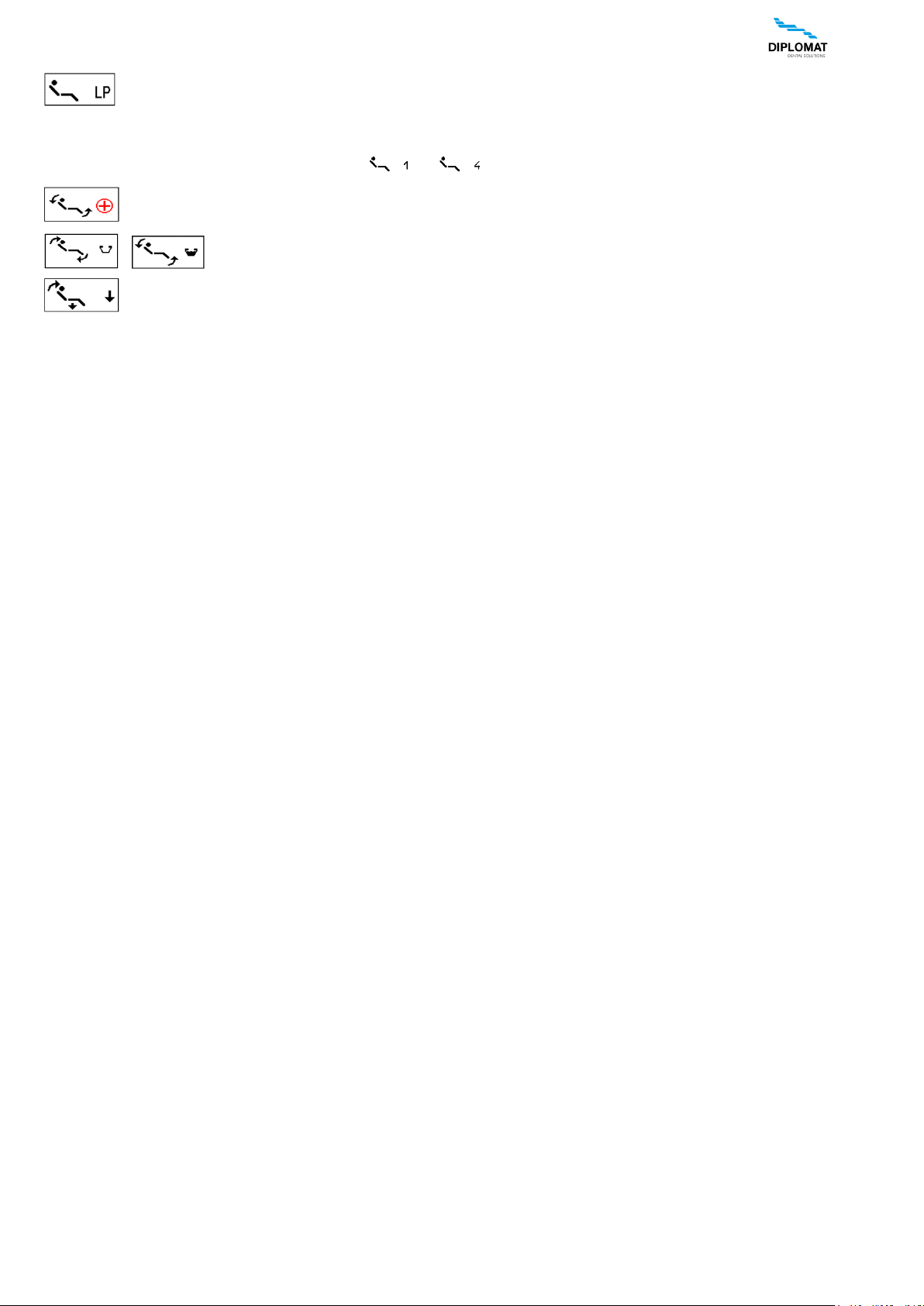
Last position – return of the chair to the previous position / from rinsing position.
Programmable positions.
These serve to save and recall pre-set positions of the chair.
The units enables four arbitrary user positions ... and three special-purpose positions :
Anti-shock position (Trendelenburg) – set by the manufacturer – not adjustable.
/ Rinsing position / Return from rinsing position
Getting-on position
Press the respective button to recall the desired position.
To program the position into the memory, set the chair to desired position and then predd and hold the button for the said
position for at least 2 seconds. Getting into program mode is indicated by beeping and changing of the colour of the
button frame. After the button has been released the position is written to the memory. If there is a danger of collision
with the bowl during setting the rinsing position, then the setting of the rinsing position is corrected automatically.
All programable position are saved separately for each user and are recalled from the memory automatically when the
user has been selected. At individual programmable positions, the movement of the bowl (if powered) is automated.
To move the chair in the upper half of the track is necessary that the bowl be in the home position.
If not, then move the chair is blocked and this is signaled by the error message E0210.
Also it blocked the movement of the chair to the programmed position, if that position requires movement of the chair in the
upper half of the track and the bowl is not in the position. Blocking in this case is indicated by a sound signal Tone--short
repeated as long as the bowl is relegated to the home position. Then the chair continues to move in the desired position.
When power operated bowl this retracts automatically.
If during the movement of the chair upwards, or the movement of the chair in the upper half of the track deflection bowl and
stops the chair! Blocking in this case is signaled by an audible signal short - long - short - long - short tone. Misu be returned
to the zero position and then repeat the command to move the chair.
The movement of the chair when striking the barrier stopped and switched to the opposite direction (backward movement
does not always occur when the backrest crash into obstacles).
The opposite movement continue until there is no release of the safety switch to stop and give the chair to an obstacle or
until the chair comes to an end position, if not to release the safety switch. During this movement echoes the warning beep
- repeating long tone. Watched them move the chair down, move the backrest backward, crashed on the assistant table
upwards. The impact to the assistant table to display medical error message E0211 - chair stops and an audible signal - 2
long beep. In this case, the return movement of the chair does not occur.
The manufacturer recommends to move the assistant table out of the chair trajectory before moving the chair to avoid the
collision of the chair with the assistant table and/or potential damage to the assistant table.
INSTRUCTIONS FOR USE DA 270, DA 370, DA 280, DA 380
UM_EN_DA270_DA280_DA370_DA380_m2015_2019-04_ver1.9 18 / 67
8.1.2 Ways of changing parameters in individual screens
The unit enables the user to set individual parameters.
The parameters can be set using several ways.
1-Setting of the value of a parameter by means of + / -
-
-
-
-
-
-
-
-
-
-
-
-
-
-
-
-
-
Press the button with respective parameter. The buttons that enable to change the value are displayed in red. Change
the value of the parameter by means of the buttons +/- .
The new value is saved temporarily (until the change of the program number) by repeated pressing of the button with the
parameter under setting or permanetly into the program by means of the button .
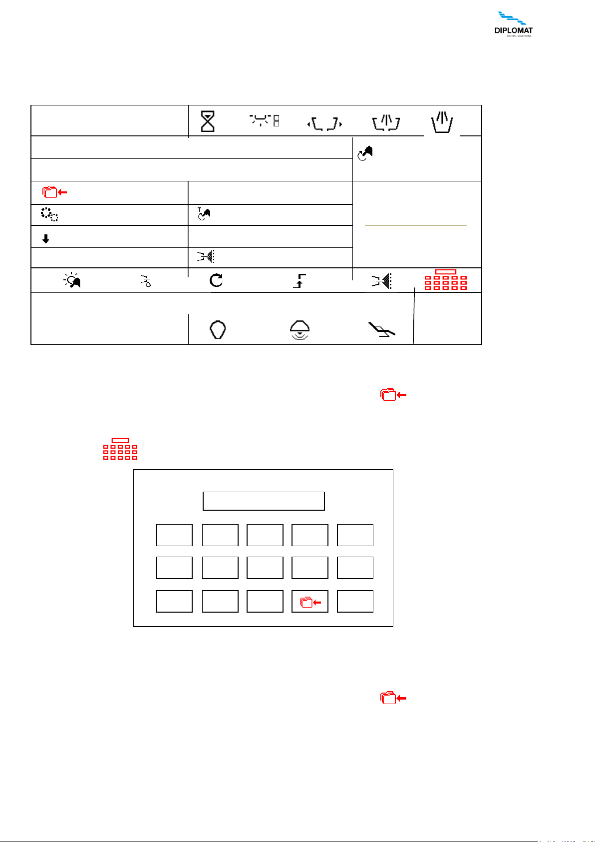
2-Setting of the value of a parameter by means of the keyboard
Press the button to see the keyboard
In the keyboard there is displayed the minimum and maximum permissible value for the parameter in question. If the
value is outside the range, this is indicated by means of „!!!“ and the value will not be accepted when pressing „OK“. The
button with decimal point is displayed only if the parameter in question enables so. To return without changing the value,
press ESC.
The new value is saved temporarily (until the change of the program number) by repeated pressing of the button with the
parameter under setting or permanetly into the program by means of the button . Button „BS“ serves to delete the
last position.
!!! 0
5
.
BS
OK
ESC
6
7
8
9
0
1
2
3
4
MIN:100 MAX:40000
> 1000 > 5000 > 20000 > 40000
P1
1:1
NORM
ENDODONCIA
PROGRAM 1
AFt 3.0s
3.5 Ncm
33%
40 000
X1/min
12.AUG 12:12
DR.SMITH
TYPE
INSTRUMENT TYPE
INSTRUCTIONS FOR USE DA 270, DA 370, DA 280, DA 380
UM_EN_DA270_DA280_DA370_DA380_m2015_2019-04_ver1.9 19 / 67
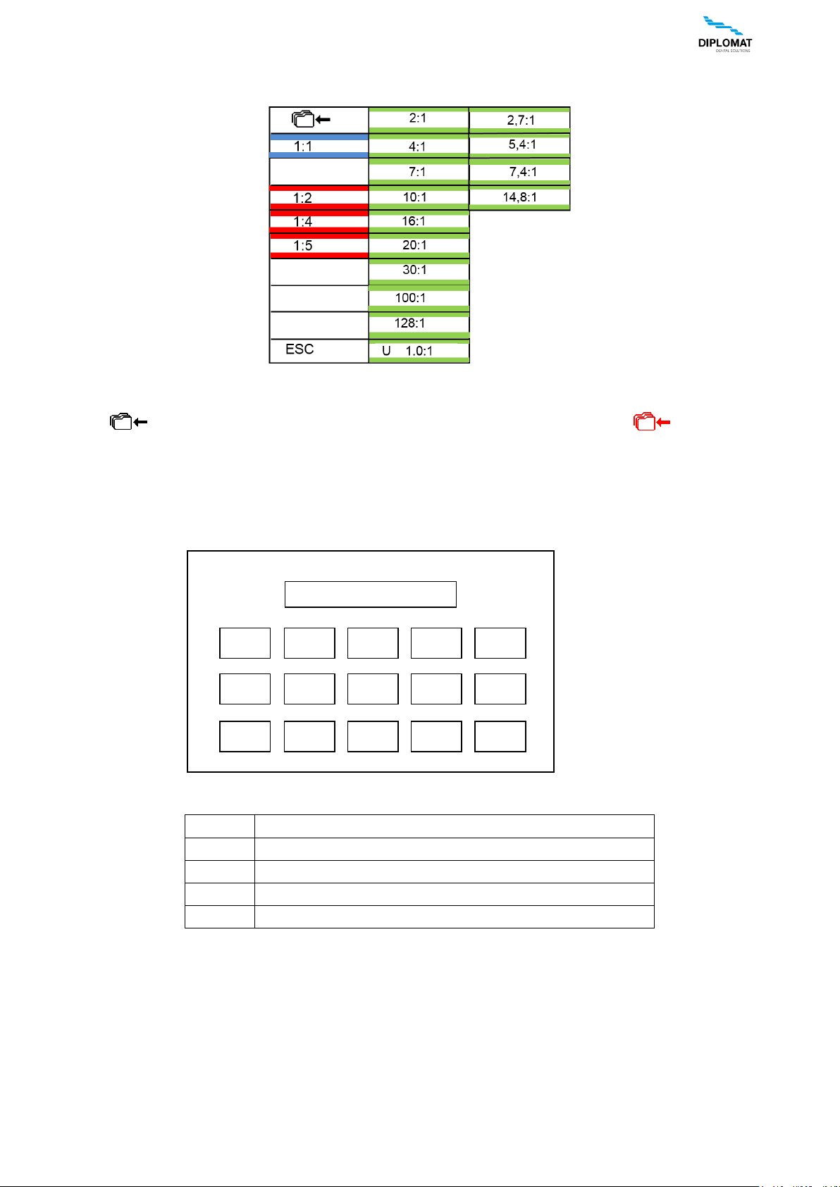
3-Setting of the value by selection from the options
Some parameters have pre-set values and their selection is made by means of a „pop-up menu“. When the button with
the respective parameter is pressed, the menu with pre-set values is displayed, e.g. for the selection of transmission ratio:
To return without changing the value, press the button „ESC“. Press the respective value to set and save it temporarily
(until the change of the program number). If you want the change to be saved permanently into the program, first press
the button . Saving into the memory of the program is indicated by change in the colour . To cancel the
saving into the memory, press the button again.
4-Editing the program name and the user name
Like numerical values, it is also possible to edit the text at program name and the user name. In that case the keyboard
looks as follows:
Symbols explained:
ESC
The button serves to return without changing the text
BS
The button serves to delete the last sign
SPACE
The button serves to insert a gap
1/A
The button serves to change-over between numbers / letters
OK
The button serves to end editing and save the changes
PROGRAM 3_
5
PQR
SPACE
BS
1 / A
OK
ESC
6
STU
7
VWX
8
YZ%
9
. , /
0
ABC
1
DEF
2
GHI
3
JKL
4
MNO
INSTRUCTIONS FOR USE DA 270, DA 370, DA 280, DA 380
UM_EN_DA270_DA280_DA370_DA380_m2015_2019-04_ver1.9 20 / 67
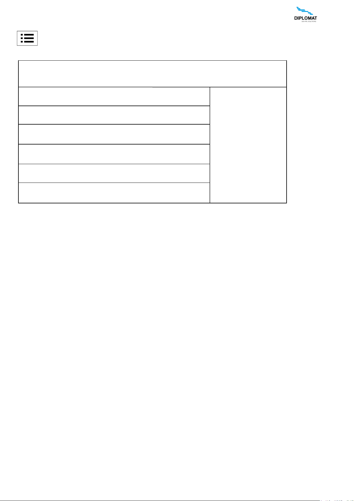
Main menu
Press the button to get into the main menu of the unit.
It enables to get access to individual settings of the unit.
ESC
SETTINGS
HYGIENE
USB
USER
SERVICE / FACTORY
TEST
INFO
INSTRUCTIONS FOR USE DA 270, DA 370, DA 280, DA 380
UM_EN_DA270_DA280_DA370_DA380_m2015_2019-04_ver1.9 21 / 67
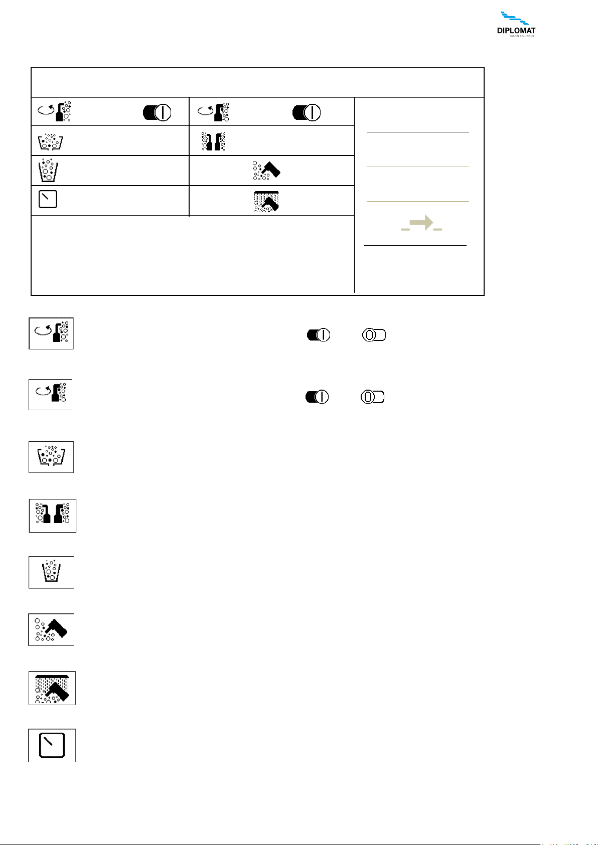
HYGIENE menu
This is optional and the menu is displayed only if the dental unit is equipped with the hygiene.
Turning the continual decontamination for the small aspirator on/off
Press the button to turn the continual decontamination of the small aspirator on/off.
The condition is indicated by means of the symbol - ON / - OFF.
Turning the continual decontamination for the big aspirator on/off
Press the button to turn the continual decontamination of the big aspirator on/off.
The condition is indicated by means of the symbol - ON / - OFF.
Starting the decontamination for the spittoon bowl
Press the button to start the decontamination of the spittoon bowl.
Starting the targeted hygiene for the big and small aspirator
Press the button to start the targeted hygiene of both aspirators.
Starting the disinfection of the cup
Press the button to start the disinfection of the cup.
Starting the disinfection of the instruments of the dentist table
Press the button to start the disinfection of the dentist table.
Starting the rinsing of the instruments of the dentist table
Press the button to start the rinsing of the instruments of the dentist table.
Setting the time of duration of disinfecting solution
Press the button to start the mode of setting the value. Set the desired time by means of the buttons + / -
and save the said time into the memory by pressing the button again.
+
-
ESC
HYGIENE
10 sec
10 sec
60 sec
50 sec
 Loading...