

Diplomat ADEPT DA 170, ADEPT DA 130 Instructions For Use Manual
DIPLOMAT DENTAL s.r.o.
Vrbovská cesta 17
921 01 Piešťany
SLOVAKIA
INSTRUCTIONS FOR USE
Dental units
DIPLOMAT ADEPT DA 170
DIPLOMAT ADEPT DA 130

INSTRUCTIONS FOR USE DA 170, DA 130
UM_EN_DA170_DA130_2018-09_ver2.6 2 / 37
CONTENTS
1 PURPOSE AND USE ........................................................................................................................................ 3
2 PRODUCT DESCRIPTION ................................................................................................................................ 4
3 TECHNICAL DATA .......................................................................................................................................... 5
3.1 Used Symbols..................................................................................................................................................... 5
4 GENERAL DESCRIPTION OF THE DENTAL UNIT DA 170 .................................................................................... 7
4.1 Label of dental unit ............................................................................................................................................ 9
5 PRE-INSTALLATION REQUIREMENTS .............................................................................................................. 9
5.1 Environmental requirements ............................................................................................................................ 9
5.2 Requirements to Input/Output Media .............................................................................................................. 9
5.3 Floor surface .................................................................................................................................................... 10
5.4 Environment .................................................................................................................................................... 10
6 ASSEMBLY AND INSTALLATION .................................................................................................................... 11
7 PUTTING THE UNIT INTO OPERATION .......................................................................................................... 12
8 PRODUCT OPERATION ................................................................................................................................. 13
8.1 Dentist’s Control panel .................................................................................................................................... 13
8.1.1 Button functions description .............................................................................................................................. 14
8.1.2 Saving the customized settings ........................................................................................................................... 15
8.1.3 Adjusting flow intensity of cooling water ............................................................................................................ 15
8.1.4 Tray table............................................................................................................................................................ 15
8.1.5 Operation of individual instruments ................................................................................................................... 16
8.2 Assistant’s Control Panel ................................................................................................................................. 18
8.3 Foot controller ................................................................................................................................................. 19
8.4 Spittoon block .................................................................................................................................................. 20
8.4.1 Distilled water bottle .......................................................................................................................................... 20
8.4.2 Central distribution of water .............................................................................................................................. 20
8.4.3 Three-position handpiece holder ........................................................................................................................ 20
8.4.4 Saliva ejector ...................................................................................................................................................... 21
8.4.5 Spittoon block configuration ............................................................................................................................... 21
8.5 Operating the dental chair .............................................................................................................................. 21
8.6 Programming of the chair ................................................................................................................................ 21
8.6.1 Writing-in of the program position ..................................................................................................................... 21
8.6.2 Programming of Sit-in (Entry/Exit) position ........................................................................................................ 22
8.6.3 Programming of Rinsing position ........................................................................................................................ 22
8.6.4 Choosing the desired pre-set position ................................................................................................................. 22
8.6.5 Toggling between programmable sets P1/P2 ...................................................................................................... 22
8.6.6 Blocking of the chair when collision with barrier ................................................................................................ 23
8.7 Headrest manual adjustment .......................................................................................................................... 23
8.8 Right side armrest position adjustment .......................................................................................................... 23
8.9 Dental operating light ...................................................................................................................................... 24
9 PRODUCT MAINTENANCE ............................................................................................................................ 25
10 CLEANING, DISINFECTION AND DECONTAMINATION .................................................................................. 26
10.1 Disinfecting the internal distilled water tubings ........................................................................................... 26
10.2 Semi-automatic disinfection of instrument’s waterlines (optional) ............................................................. 26
10.3 Cleaning and decontaminating the saliva ejector ......................................................................................... 29
10.4 Cleaning and decontaminating the large and small aspirators ..................................................................... 29
10.5 Cleaning of the sieve of the separation block ............................................................................................... 29
10.6 Cleaning and Disinfection of Dürr spittoon valve on wet suction system (optional) .................................... 30
10.7 Decontaminating the cuspidor bowl ............................................................................................................. 31
10.8 Cleaning, disinfection and decontamination of other parts of the dental unit ............................................ 32
11 EQUIPMENT DISPOSAL .............................................................................................................................. 33
12 REPAIR SERVICE ........................................................................................................................................ 33
13 WARRANTY ............................................................................................................................................... 33
14 CONTENTS OF THE PACKAGING/PACKAGE CHECK LIST................................................................................ 34
15 TRANSPORTING ........................................................................................................................................ 34
16 STORAGE .................................................................................................................................................. 34
17 REQUIREMENTS ON ELECTROMAGNETIC COMPATIBILITY ACCORDING TO EN 60601-1-2 ................................. 35
INSTRUCTIONS FOR USE DA 170, DA 130
UM_EN_DA170_DA130_2018-09_ver2.6 3 / 37
1 PURPOSE AND USE
These Instructions for use are intended to provide you with necessary information about using DIPLOMAT ADEPT DA
170, DA 130. Intended purpose of use of dental unit:
Equipment, used alone or with instrumentation, intended for prevention, treatment or alleviation of illness in the area of
oral cavity of the patient. Dental unit is part of dental equipment, formed by a set of interconnected subassemblies of
dental equipment and instruments, forming a functional unit for dental treatment. Contraindications associated with the
use of dental unit are not known.
Please, familiarize yourself with information provided in this handout before operating the unit. It is
expected, that dental unit will be used by a specialist, familiar with the following instructions for use as well
as with the instructions for any other products and applications that are being used in conjunction with a
unit. To ensure proper operation installations and/or adjustments should be done by authorized technicians
of authorized organization. The utilities requirements as well as the installation requirements specified in
DIPLOMAT ADEPT DA 170, DA 130. Instructions for Use must be observed.
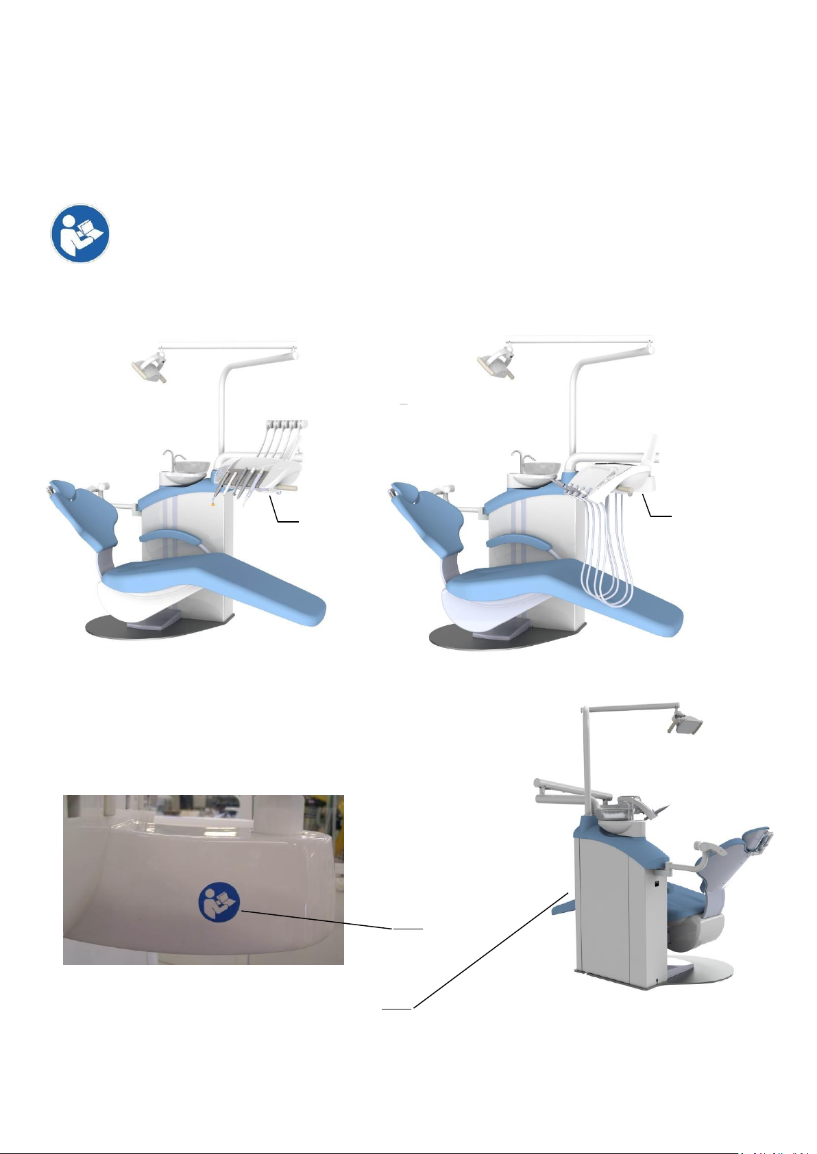
1
1
2
3
Fig. 1.1 Diplomat Adept DA 170 Fig. 1.2 Diplomat Adept DA 130
1. Data plate location
2. Main switch location
3. Safety sign

INSTRUCTIONS FOR USE DA 170, DA 130
UM_EN_DA170_DA130_2018-09_ver2.6 4 / 37
2 PRODUCT DESCRIPTION
Diplomat DA 170 and DA 130 are stationary dental units with built-in chair. The pantographs of a control panel and of
operating light are mounted on the spittoon block. The instruments and handpieces, except for syringe, saliva ejector,
large and small aspirators and polymerizing lamp, are controlled with the foot controller. The keyboard with control
buttons and light indicators is located on the control panel. The handle enables a smooth repositioning of control panel.
In the standard configuration, the handle is mounted on the right side of the control panel. The control panel with leftside handle is available upon request. Depending upon the model, spittoon block can be equipped with saliva ejector
and with large and small aspirators. Fixed or swiveling spittoon bowl (upon request). The glass cuspidor bowl, rinsing
and cup-filling spouts are detachable. The silicone pads on the tray table as well as the silicone handles are detachable
and sterilizable. Large and small aspirators' handpieces are also detachable and are disinfection- and sterilizationfriendly. Saliva ejector tips are for single use only. As an optional furnishing, light console-mounted tray tables as well
as the monitor arm are available upon request.
All the DA 170, DA 130 units are equipped with a syringe on a control panel.
The following control panel configurations are available:
• 1x syringe
• max. 3 rotary instruments, among which are
o max. 2 turbines
o max. 2 micromotors (max. 2x DC motor or max. 2x BLDC motor)
• 1x ultrasonic scaler
• max. 5 instruments with lighting
• 1x polymerizing lamp
DC and BLDC motors cannot be mounted simultaneously
The assistant panel can be fitted with the following instruments:
• 1x large aspirator
• 1x small aspirator
• 1x saliva ejector
• 1x camera
• 1x polymerizing lamp
• 1x syringe
Note
Optional equipment and supplementary equipment (see the current price list).
In the manual are used following shortcuts:
USS - ultrasonic scaler (calculus remover)
PLM - polymerizing lamp
DC motor – brushed motor
BLDC motor – brushless motor
Parts of the dental unit coming into contact with the patient:
• Seat
• Backrest
• Headrest
• Handrest
• Small and large aspirator
• Saliva ejector
• Instruments located on the control panel
INSTRUCTIONS FOR USE DA 170, DA 130
UM_EN_DA170_DA130_2018-09_ver2.6 5 / 37
3 TECHNICAL DATA
Supply voltage
220V – 230 V ± 10%
Frequency
50/60 Hz ± 2 %
Max. power input at 220-230V, 50/60 Hz
1500 VA + 10%
Input air pressure
from 0,45 to 0,8 MPa
Input water pressure
from 0,3 to 0,6 MPa
Dental unit weight with chair part (netto) DA170, DA130
145 kg + max.25 kg accоrding to equipment
Type of shock protection
Class I equipment
Degree of shock protection
Applied parts of B type
Degree of protection by cover
IP21
Water temperature for the cup
33 ± 5°C (with heater fitted)
Tray table recommended max. load
0,5 kg
Side table recommended max. load
3 kg
Dental Chair
Chair seat lifting range
390±10mm÷795±20mm
Back rest inclination angle (from vertical position)
18° ± 2° ÷ 88° ± 3°
Vertical positioning cycle duration of the chair
18s ± 3 seconds
Backrest positioning cycle duration
17s ± 3 seconds
Maximum Patient load (EN ISO 6875)
200kg
Operating mode
1:16 (cycle: e.g. 25secs run, 400secs rest)
Noise level
max. 54dB
Dental unit weight with chair part and packing
210 kg + max. 40 kg
Caution
To eliminate the risk of electric shock, equipment must be connected to the mains supply with a reliable
connection to protective earth.
Operation mode is continuous with intermittent loading, common to the dental practice.
Detailed descriptions, schematics, parts list and instructions for servicing are available to each authorized service
specialist who was trained in DIPLOMAT DENTAL.
3.1 Used Symbols
Symbol
Description
Caution
Note
Refer to instruction manual/booklet
Operator´s manual; operating instructions
IP21
Protected from touch by fingers and objects greater than 12 millimeters. Protection
against vertically falling drops of water e.g. condensation
Date of manufacture
Manufacturer
Mandatory comformity marking for certain products sold within the European Economic
Area

INSTRUCTIONS FOR USE DA 170, DA 130
UM_EN_DA170_DA130_2018-09_ver2.6 6 / 37
This way up
Stacking limit by mass
Stacking limit by number
Fragile, handle with care
Keep away from rain
Temperature limit
Humidity limitation
Atmospheric pressure limitation
Type B applied part
Fuse
Equipotential terminal
Protective earth; protective ground
Dangerous voltage
Hot surface
Sterilizable in a steam sterilizer (autoclave) at temperature specified
Symbol indicating separate collection for electrical and electronic equipment (EEE)
consists of the crossed-out wheeled
Similarly, the Tidyman is not a recycling symbol. It’s merely to convey the message ‘Do
not litter’
Packaging symbol – Polyvinyl Chloride
Packaging symbol - Paper
Packaging symbol - Steel
Packaging symbol - Wood
INSTRUCTIONS FOR USE DA 170, DA 130
UM_EN_DA170_DA130_2018-09_ver2.6 7 / 37
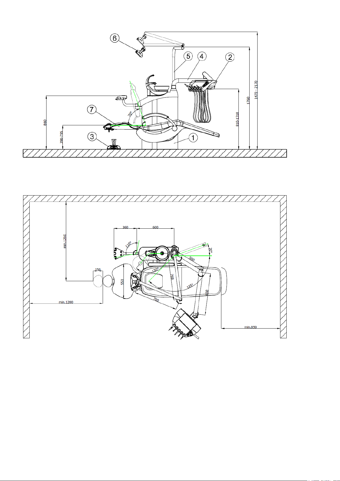
4 GENERAL DESCRIPTION OF THE DENTAL UNIT DA 170
1. Spittoon block
2. Control panel
3. Foot controller
4. Control panel console
5. Dental light pantograph
6. Operating light
7. Dental chair
GENERAL DESCRIPTION OF THE DENTAL UNIT DA 130
INSTRUCTIONS FOR USE DA 170, DA 130
UM_EN_DA170_DA130_2018-09_ver2.6 8 / 37
1. Spittoon block
2. Control panel
3. Foot controller
4. Control panel console
5. Dental light pantograph
6. Operating light
7. Dental chair
INSTRUCTIONS FOR USE DA 170, DA 130
UM_EN_DA170_DA130_2018-09_ver2.6 9 / 37
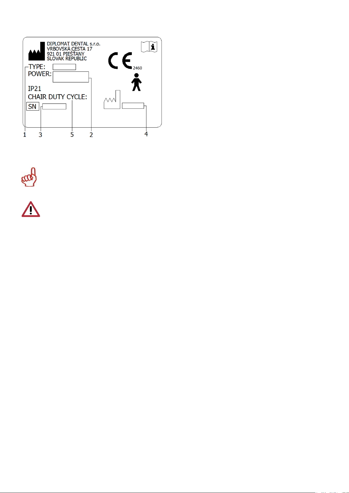
4.1 Label of dental unit
5 PRE-INSTALLATION REQUIREMENTS
Warning
Pre-installation and installation must be performed according to the applicable standards of the particular
country and in accordance with the valid documentation of the manufacturer, which is owned by each
authorized representative of DIPLOMAT DENTAL s.r.o.
Caution
To avoid the risk of electric shock, device must be connected to the power supply with a protective earthing
Do not modify this device without prior authorization of the manufacturer.
5.1 Environmental requirements
Do not install in premises with a potential explosion hazard.
5.2 Requirements to Input/Output Media
Water
It is required to use only drinkable water with input pressure of 0,3 MPa to 0,6 MPa with the flowrate higher than 5
l/min., without particles bigger than 50 µm, which might clog the small cross sections of the pipes of the dental unit. If
the water contains particles bigger than 50 µm, then there must be introduced 50 µm advance filter/strainer.
Water hardness must be less than 2,14 mmol/l.
The pH must be in the range of 6,5 to 8,5.
Maximal electrical conductivity of the water shall not exceed 2000 µS/cm.
Water must comply with the local regulations for drinking water.
Cooling of instruments using water from the central distribution
In the unit's central water distribution, there is included a shut-off valve and the valve to prevent reverse flow of water.
Requirements and recommendations:
• If the central water is used for cooling of dental instruments, then it is necessary to install particle filter with precision
of 5 µm before the water enters dental unit.
• Hard water can lead to dysfunction of the dental unit.
If the water contains more than 50 mg of CaO/l or 36 mg of MgO/l, then it is necessary to include water softener
device (for adjusting the hardness of the water) connected at the input of the water distribution.
This water treatment device is required in case when distilled water is not used.
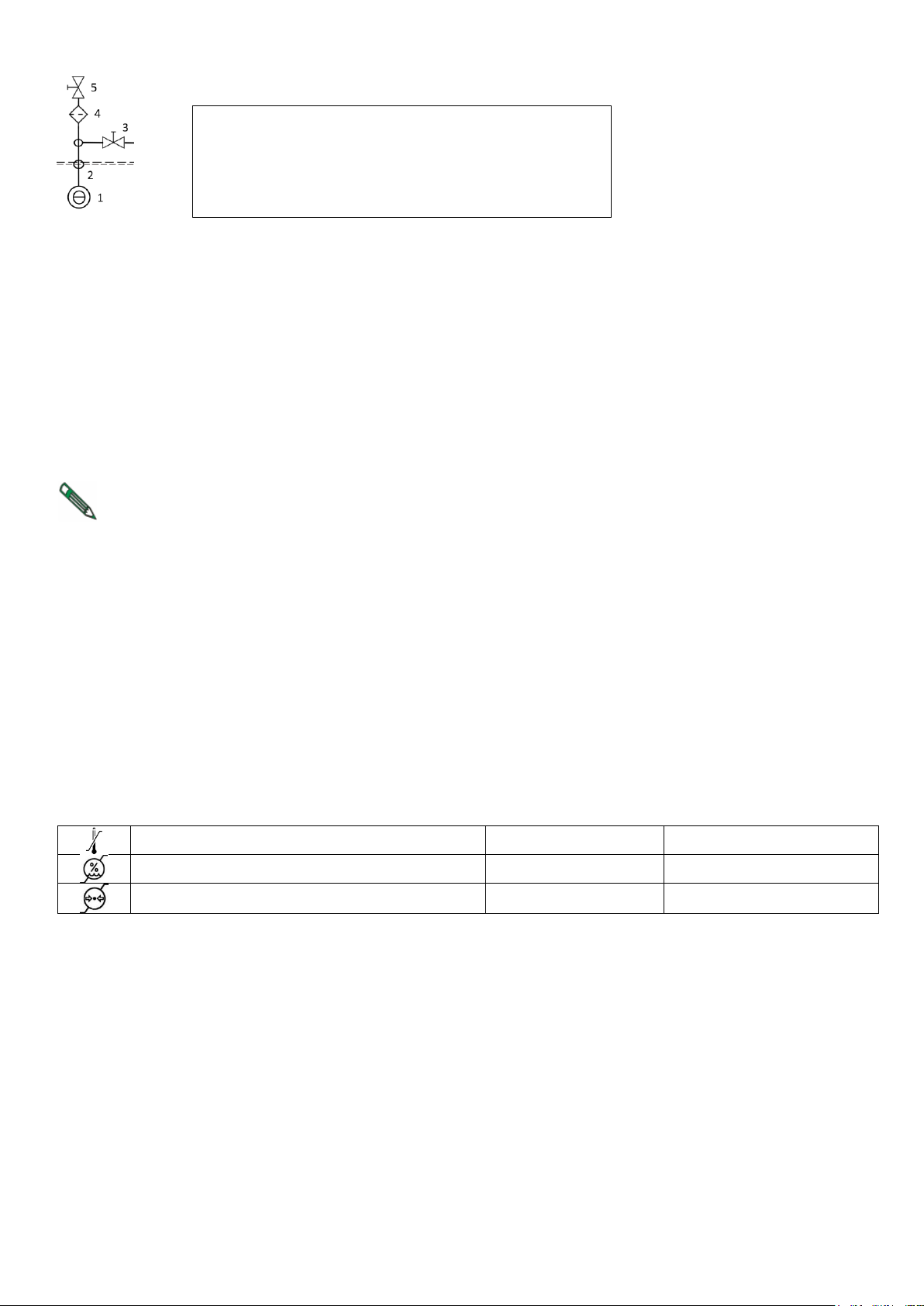
• When there is a requirement to install the mount point for the sampling input water, the following diagram shows the
recommended location mount point for the sampling input water.
The said devices are not integral parts of the dental unit.
Connection diagram of input elements in dental unit (STN EN ISO 7494-2:2015)
1. Model of the unit
2. Basic electrical parameters
3. Serial number
4. Production date
5. Operation mode of the chair
INSTRUCTIONS FOR USE DA 170, DA 130
UM_EN_DA170_DA130_2018-09_ver2.6 10 / 37
Air
Oil-free, clean and dry air, with a minimum flow of 55 l/min and a pressure of 0,45 to 0,8 MPa.
Suction (for cuspidor block equipped with large and small aspirators)
Static vacuum index must be measured at the spot and must be within the range of min. 0,005 MPa (50 mbar) to max.
0,02 MPa (200 mbar). If the static vacuum index is higher than 0,02 MPa, then suction CONTROL valve should be
connected to the suction branch in order to limit the max. vacuum to 0,02 MPa. This regulating valve is not a part of the
kit. The suction unit must produce the flowrate of at least 450 Nl/min. measured at the spot.
Waste
The waste /drain/ branch must have continuous slope of min. 1% and min. flowrate of 10l/min. and must have no sharp
bends and sections that might cause backflow. Do not use the same waste branch in conjunction with another dental
unit or a basin. It is allowed to use polypropylene or cured polyethylene tubes.
Note
If the local regulations require an installation of an amalgam catcher, then the cuspidor block which is not
equipped with the amalgam separator, must be connected to an external amalgam catcher. Amalgam catcher
should be installed according to the manufacturer's instructions for the product.
Recommended mains fuse rating
Recommended fuse rating for the supply main is 16A. (If using a circuit breaker, use circuit breaker "C" type). No other
equipment should be connected to the supply main! Max. Electrical power input of dental unit is 1500 VA. The supply
main must conform to prevailing local codes.
Recommendation
The manufacturer recommends installation of an instantaneous residual-current device with 30mA sensitivity, if
installation of such does not contradict local regulations.
If all the conditions fit the pre-installation requirements, the dental unit can be installed and connected to the utilities.
5.3 Floor surface
The floor must have at least 100 mm thick concrete foundation. The floor slope should not exceed 1%. Antistatic floor is
recommended.
5.4 Environment
Ambient temperature range
from +10 °C
to +40 °C
Relative humidity range
from 30 %
to 75 %
Atmospheric pressure range
from 700 hPa
to 1060 hPa
1 - Input water from an external water supply
2 - Mount point of inlet water
3 - Mount point for taking the samples of the input water
4 - Filter of water particles
5 - Manual shut-off valve

INSTRUCTIONS FOR USE DA 170, DA 130
UM_EN_DA170_DA130_2018-09_ver2.6 11 / 37
6 ASSEMBLY AND INSTALLATION
The installation must be done by the certified service technician only; otherwise no possible future warranty
claims will be accepted. The Registration form must be filled out and sent to the manufacturer or the seller.
Unpacking the unit and inspecting the delivery
Examine the package for any outside indication of damage. If any damage is found do not open the package and notify
the forwarding agent or the seller immediately. In case no outside damage is found, carefully open the package and
unpack the individual parts of the dental unit. Check all the parts for damage, quantity, etc. to the enclosed check-list.
Warning
In the case of the installation of the base (installation) plate, we recommend to isolate the installation plate
around its perimeter by transparent silicone sealant against the floor.
When not isolated with a silicone sealant, it may occur damage of the product, caused by the influence of water
and cleaning detergents, for which the manufacturer might not recognize any complaint.
INSTRUCTIONS FOR USE DA 170, DA 130
UM_EN_DA170_DA130_2018-09_ver2.6 12 / 37
7 PUTTING THE UNIT INTO OPERATION
Warning – disinfection of new dental unit before its first use
Before putting the unit into operation, your technician must carry out disinfection of waterlines of
instruments, according to instructions in Installation manual.
1. switch on the compressor and let it get pressurized
2. open the central water supply
3. turn on the suction unit (for cuspidor block configuration with large and small aspirators)
4. turn on the main switch located on the chair (fig. 1.3) – position I, the indication light lights on
The unit is connected to the water and air distribution. After approx. 30 s have passed, the unit is ready for work. It is
necessary to wait for approx. 2 mins. For the water to be warmed up to the desired temperature, if the electrical water
heater is installed. Do not take out any instruments or press keyboard buttons when turning the dental unit on. The foot
controller should be at a standstill.
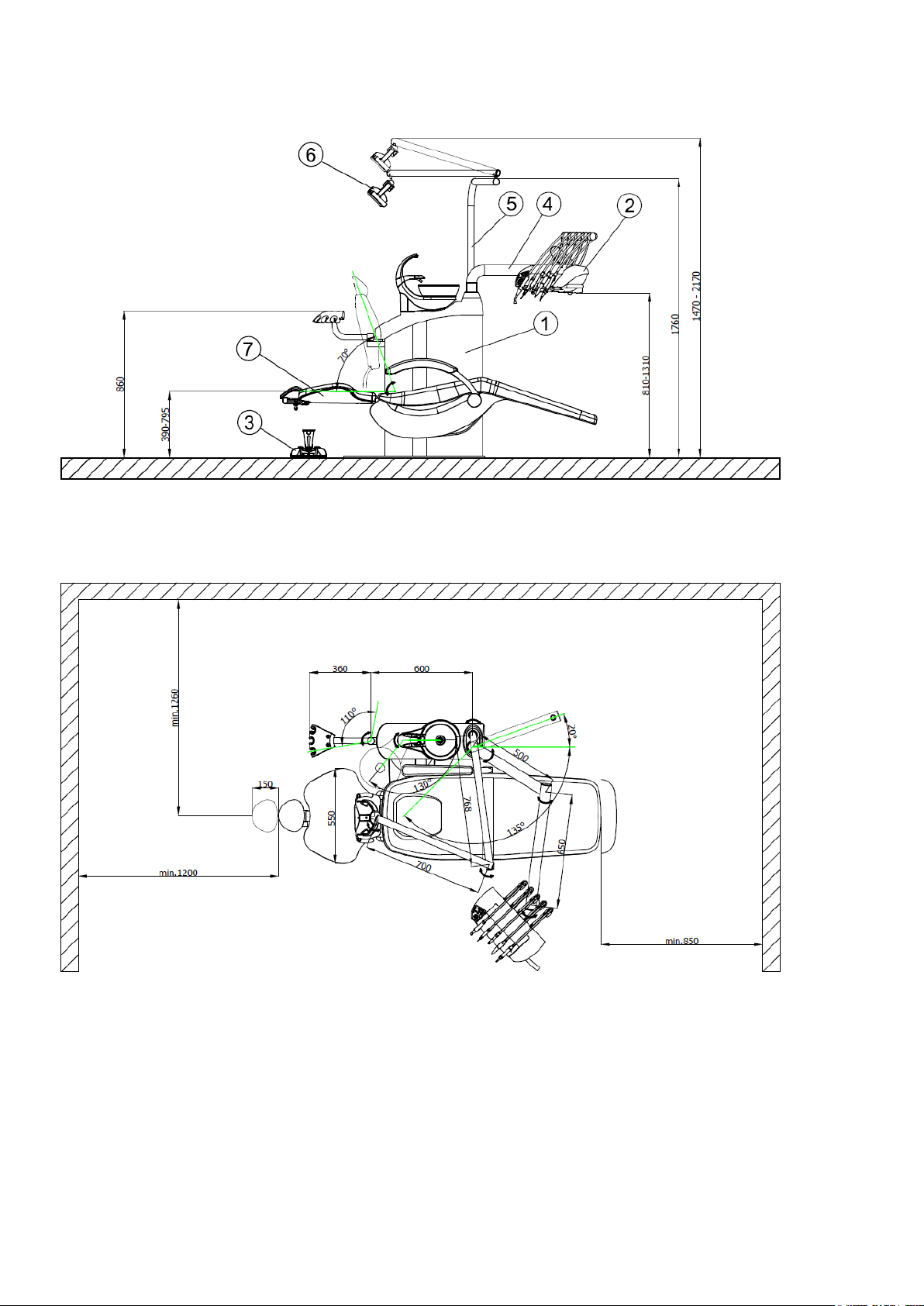
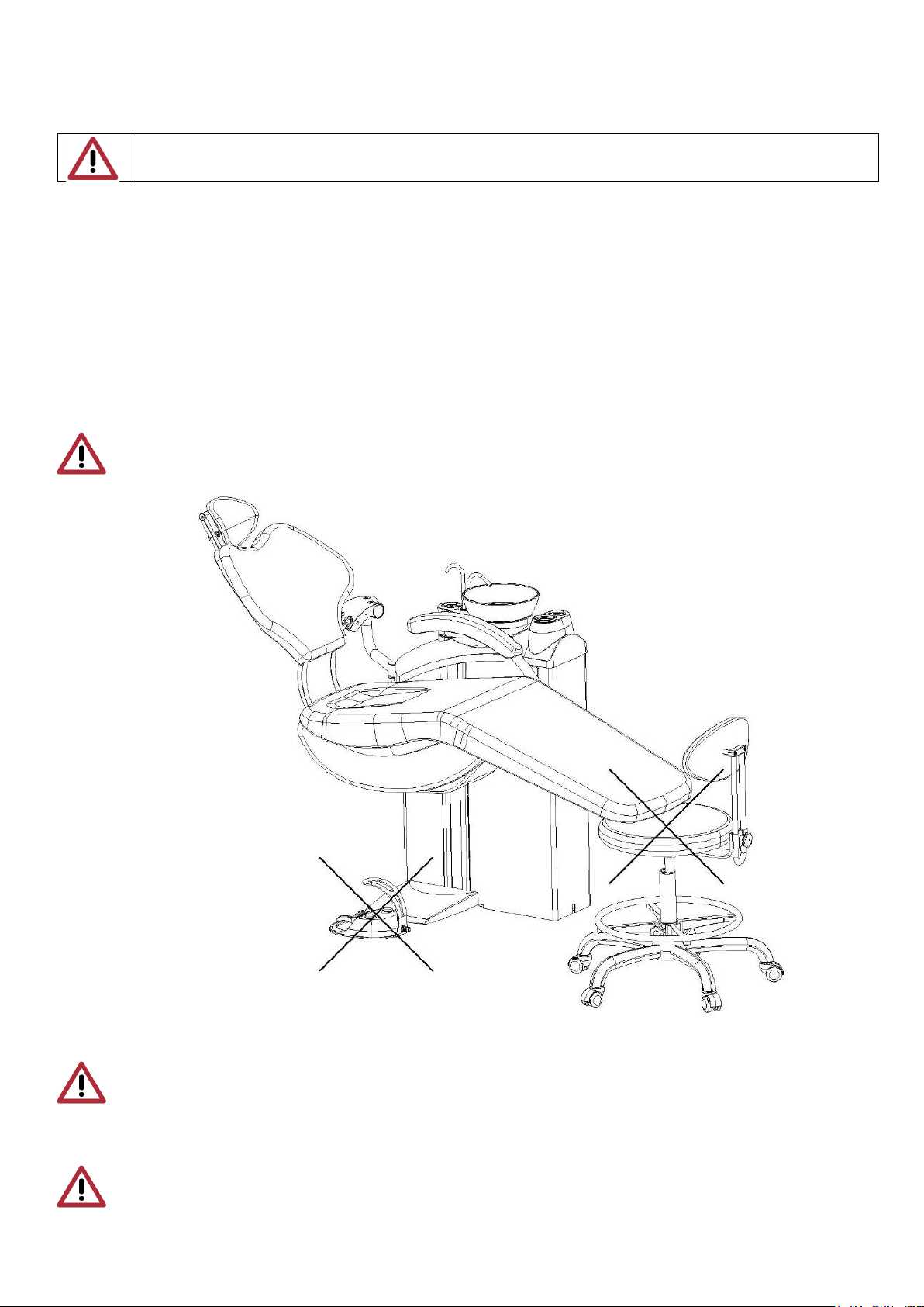
Caution
Dental chair, foot controller or other things should be positioned so that they do not obstruct dental chair or
dentist’s stool motion (see fig.)
Caution
Except for the saliva ejector, large and small aspirators (depending on modification) polymerizing lamp and
syringe (on the control panel and on the assistant table) only one instrument can be used or taken out at a
time
Caution
Except for common handling with the dentist control panel and permissible loading of the tray table, the
pantographic arm of the control panel must not be loaded by persons or articles leaning against it,
suspension of persons or articles or by other similar manners.
 Loading...