

1.5 kW Automatic Remote Controlled
Balanced Antenna Tuner
Model AT- 615B
Short Form Manual
10/2010
Dipl.Ing. Klaus Bemmerer
RF Communication Electronics
Niendorf-Middeldor 11
23769 Fehmarn
GERMANY
Phone +49 4371 869145
Fax +49 4371 869154
www.hamware.de
eMail: service@hamware.de
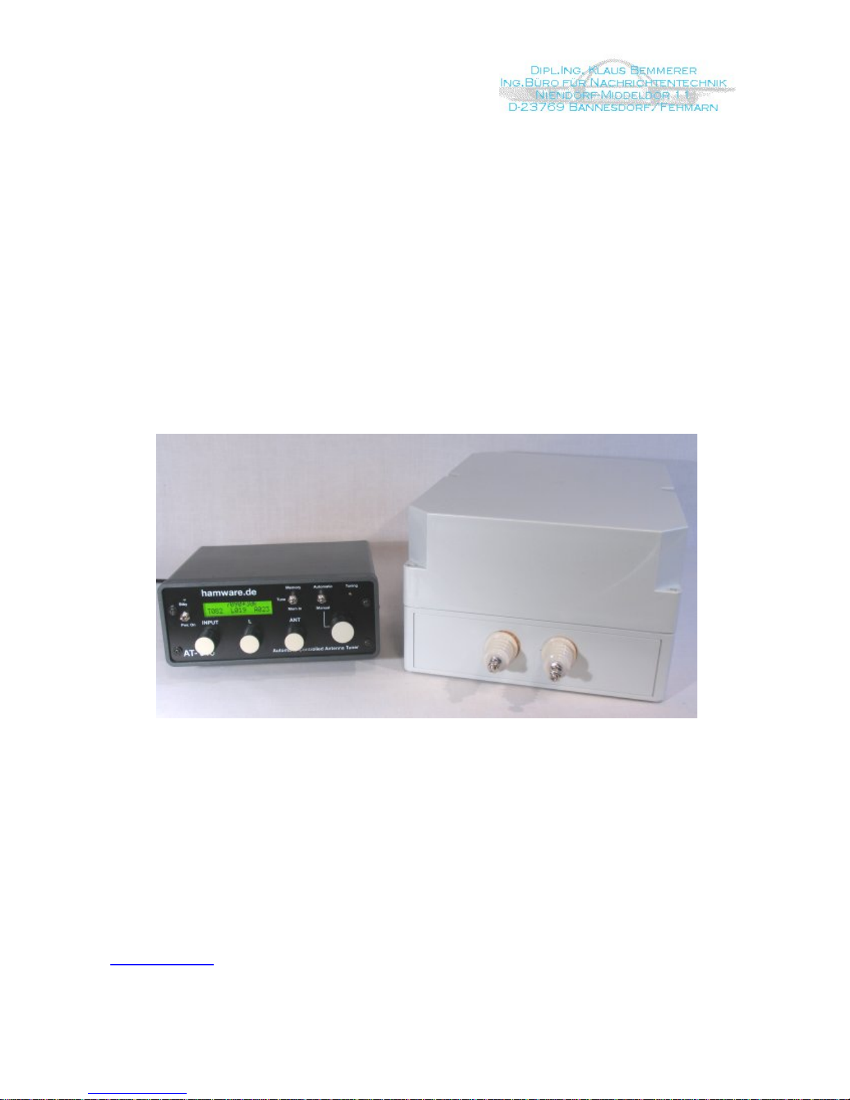
Antenna Tuner System AT-615B Description
This tuner is designed to match remotely, balanced HF antennas. This unit features
automatic selection of tuner settings based upon transmitted frequency. Unique to this
tuner, no special cabling or adapters are required. The operator simply transmits into the
antenna and the tuner detects the transmitted frequency and selects the correct settings
from memory. The Ham bands are divided into 85 operator programmable memory
locations. It will handle 1500 watts of SSB or CW power, and it can be used in either
automatic or manual mode.
The matching circuit consists of a remotely tuned balanced π circuit. The balun is placed
at the input of the tuner. The Output capacitor is a stepper motor controlled High Voltage
variable capacitor.
The Control Cabinet contains the tuning controls, memory location selection, Automatic or
Manual switching and a display that indicates the memory location in use, the frequency
range as well as the span, and the tuner settings.
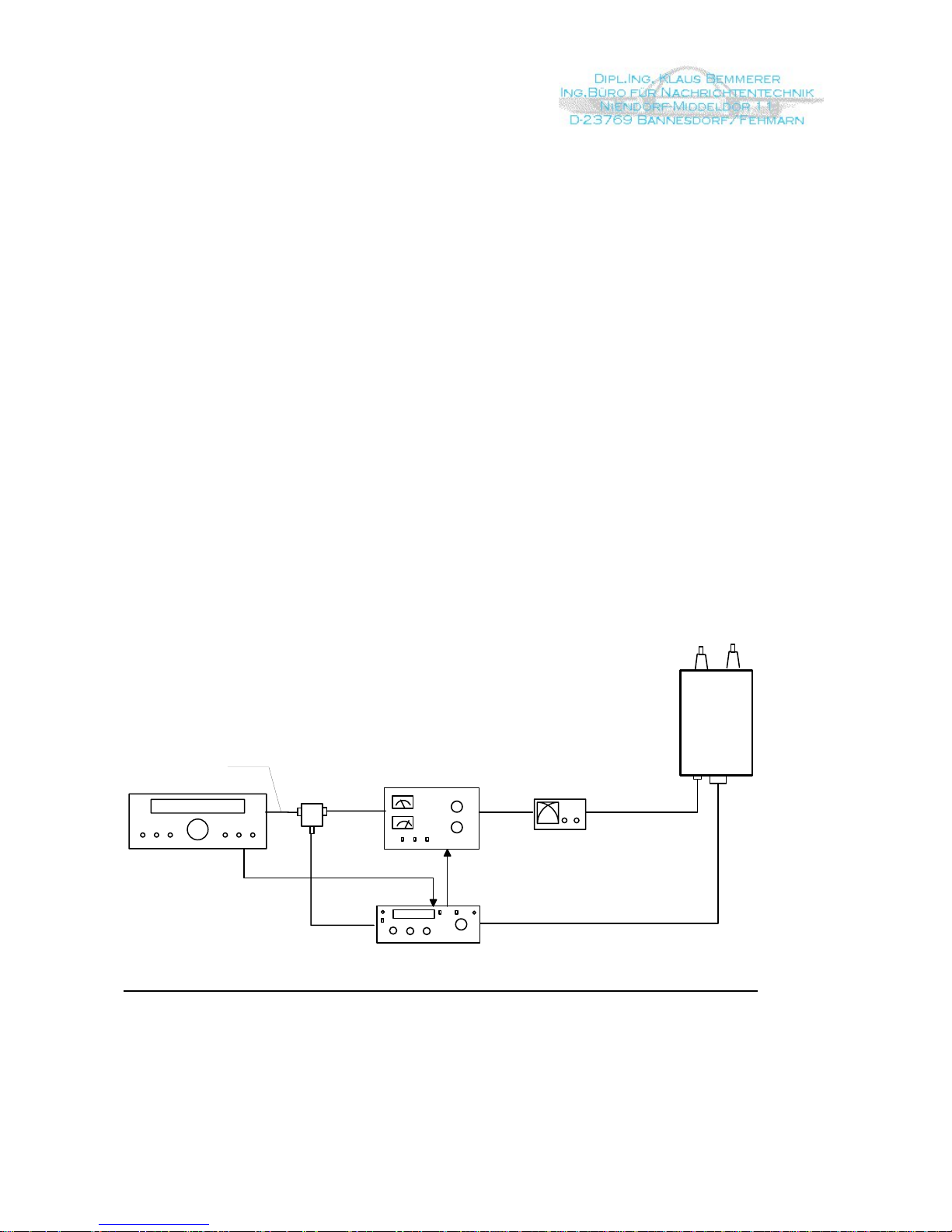
Tuner System Block Diagram
Transceiver
SWR Meter
Control Cable
Coax 50 Ohm
AT-615B Automatic
Controller
HF-Sensor
RF Probe
AT-615B
Tuner
Antenna
max. 40m (120 ft)
RF Outdoor
Unit
Power Amplifier
Steuerung Endstufe
Key Line
max. length 15 cm
Page 2 of 24
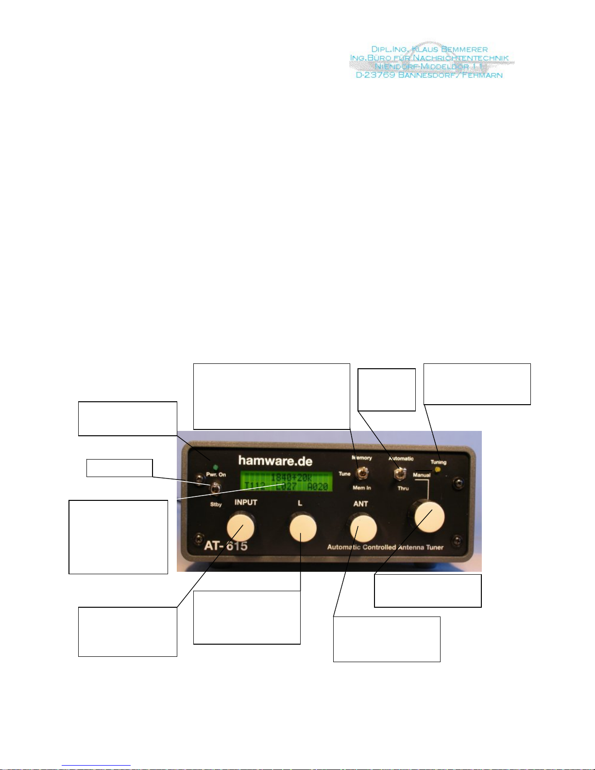
Controller Unit:
Antenna matches are stored into a bank of 85 memory locations. Each memory location is
a fraction of an amateur band. Refer to the technical section for the fractional segments for
each band. As shown in the picture below, the upper line of the LCD shows the actual
memory location chosen (lower edge frequency 1840 kHz) with its span (20 kHz). The
control settings for this frequency are shown in the lower line of the LCD. In the Automatic
Mode the memory location and its stored settings is selected by the transmitted input
frequency. The input frequency is obtained from an RF probe. The memory location
contents can be erased by a push button on the back of the controller.
The controller contains 3 rotary encoders that control the tuner elements TRX, L, and ANT.
TRX controls the Input Capacitance, L controls the Inductance and ANT the output
capacitance values. The lower line on the display shows these values.
A manual selector switch is provided for memory selection in the Manual mode.
Controller Unit
LED is lighted when
Power Supply operates
and Power Switch is off
Power Switch
L values switchable in 31
steps.
Never switch with full
poser! Max. switching
power 300W
Control of the variable
output capacitor. 1 step
corresponds to 0.9° tuning
angel. Max. 200 steps
Memory: Read out of the stored settings in
either automatic or manual mode.
Tune: Matching the antenna with the rotary
switches Input, L and ANT
Mem In: By pressing this momentary switch
down the indicated control settings are
stored into memor
y
Input Capacitors
switchable in 256 steps,
17pF each. Steps appear
upon LC Display following
“Txxx”
In „Manual“ mode all
memory locations can be
selected
LC Display
The upper row shows the
actual memory location
(lower edge frequency
with the span)
The lower row shows the
actual control settings for
the antenna
Mode switch
„Manual“ or
„Automatic“
or “Thru”
Yellow LED lights, as long
as tuning proceeds. Don’t
key the transmitter during
this time
Page 3 of 24
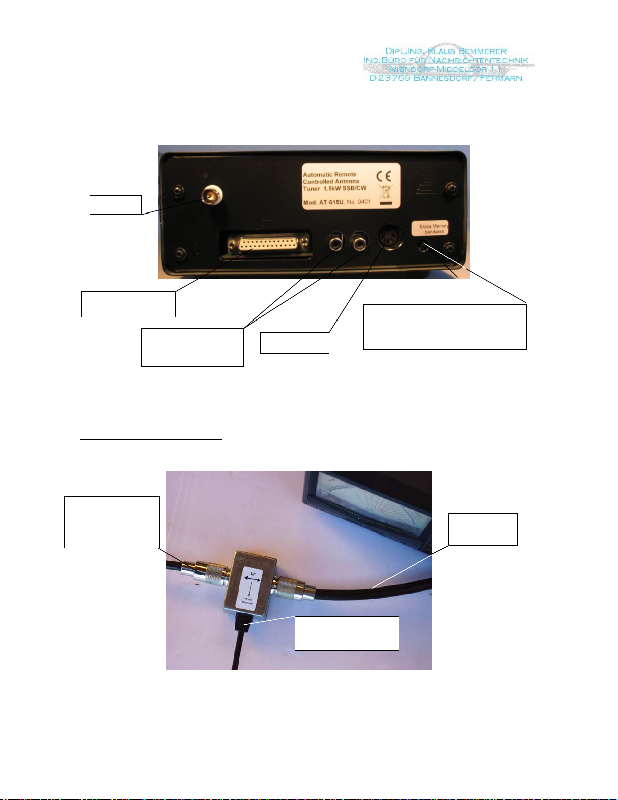
Controller Connections (Rear Side)
RF Probe
25-pin. Control Cable
to Tuner Unit
Power Supply
If the Memory Erase Button is pressed, all
memory locations associated with the band
indicated on the LC Display will be erased
Cinch-Connectors to
loop-in the key line of
Power Amp
RF Probe Installation
Probe Connector to
Controller AT-615
The connection to
the Transceiver
should made as
short as possible.
To Power
Amplifier
RF Probe
If possible, the RF Probe should be attached directly to the antenna jack of the transceiver
using an adaptor or a very short cable.
Page 4 of 24
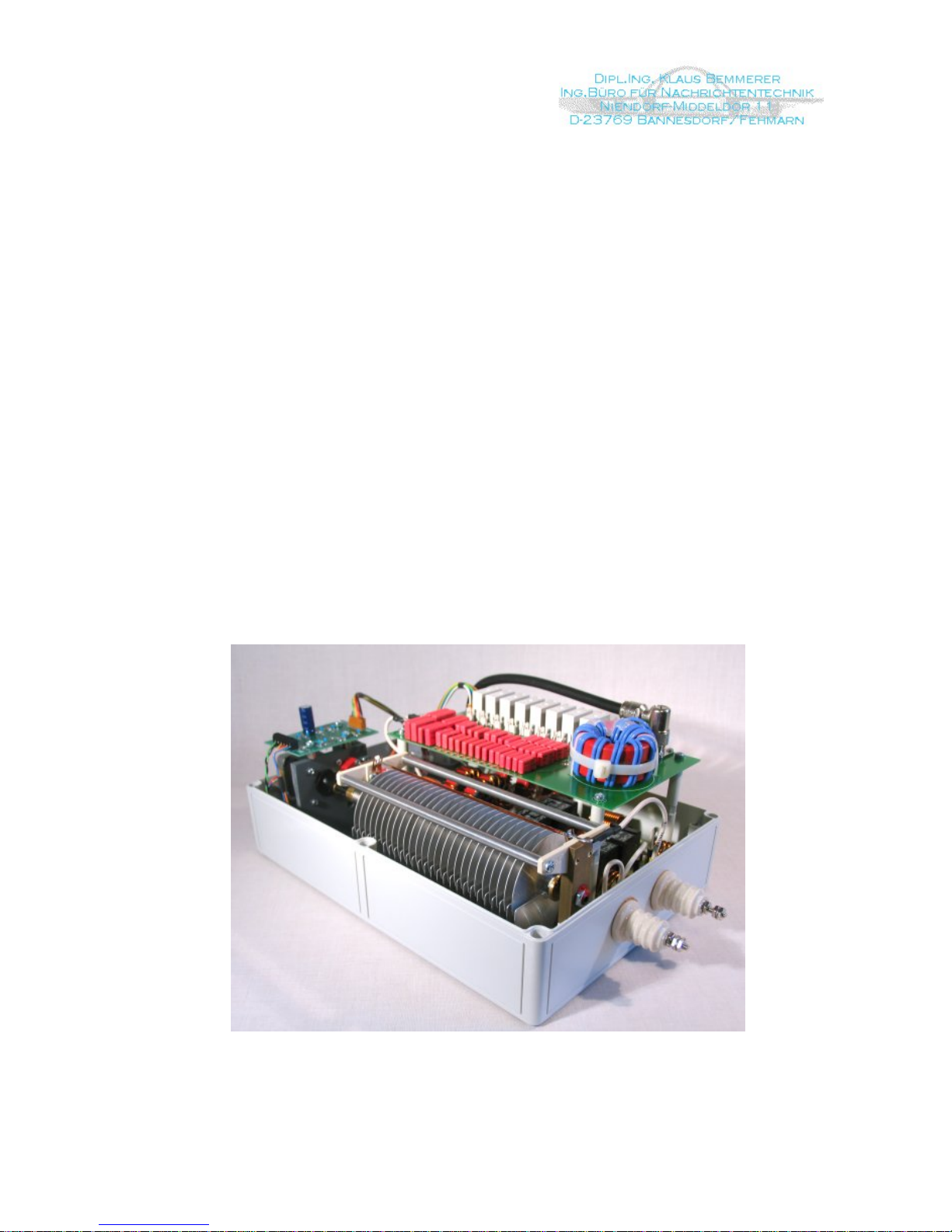
RF Unit:
The RF Unit is contained in a weather-protected cabinet (IP66) and is UV resistant. There
are two feed-thru insulators to connect to the antenna elements. The coaxial cable and the
control cable are connected via a N and a 25 pin connectors. There is no active circuitry
inside the RF Unit. This is to insure reliable operation even under non-matched condition.
The LC network is known as Balanced PI. At the front end of the network there is a balun
transformer that matches the unsymmetrical coax cable to the symmetrical tuner elements.
This is the only place where the impedance of the system is purely resistive (when
matched) and is the ideal place for the Balun. The regular station SWR meter (or the builtin meter in the TRX) is used as an indicator to match the antenna.
The capacitors at front end are switched in 256 steps of 17 pF per step. The capacitor at
antenna side is a variable capacitor of 400 pF. The control of this capacitor is by a stepper
motor with 0.9° per step. The inductive paths between the capacitors are switched in 31
steps from 0.2 µH to 35 µH. Switching is done by power relays. With the circuit
components used it is possible to match short antennas up to an unlimited antenna length
within the RF range from 1.8 to 30 MHz.
.
Interior view of the RF unit looking at the capacitor board, the inductor board is located below
Page 5 of 24

Installation of the RF Unit
239
3
4
6
6 Befestigungsbohrungen 5 mm
The weather proof cabinet has 6
mounting holes.
The backside of the cabinet
should be mounted on a flat
surface.
Hole spacing is 13.62”H x 9.41”W
(346mm x 239mm)
Connect the ground bolt between
the two antenna insulators with
the lightning rod.
An application example
If the RF Unit is installed outside, a small roof or overhang is recommended to protect the
unit from direct sun. If the tuner is not protected, the excessive temperatures inside the
cabinet could damage the antenna tuner elements.
Page 6 of 24

Control Cable
With a 25conductor (AWG22) wire control cable, the RF Unit can be controlled within a
length of 120ft. (40 meters). Lengths in excess require larger wire diameters. Cable shield
is not necessary.
37
8
141516171819202122232425
111213 10 9 6 5 4 2 1
DB-25 Controller Plug
View upon selder side of the plug
Nr. Farbe Funktion Nr. Farbe Funktion
1152
3
4
56.7
8
9.
10
11
12
13 14
16
17
18
19 20
21
22
23 24
25 26
27
29
28
30
31
32 33
34
35
36
37
Anschluss der HF-Einheit
Blick auf die Lötseite der
Buchsenkupplung
Control Cable Interface
RF Unit
View upon solder side
of the jack
1 Black Stepper Motor A 14 Blue/Bwn +15VDC
2 Wht/Blue Stepper Motor B 15 Grey/Pink Stepper Mptor C
3 Red Stepper Mptor D 16 Wht/Yel +36VDC
4 Blue GND 17 Wht/Red Stepper End Position Sw.
5 Pink +15VDC 18 Yel/Bwn RFU C10
6 Pink/Bwn RFU C9 19 Bwn/Red L-Ctl. 2^6 (MSB)
7 Grey L-Ctl. 2^5 20 Blue/Red L-Ctl. 2^4
8 Yellow L-Ctl. 2^3 21 Wht/Grey L-Ctl. 2^2
9 Wht/Pink L-Ctl. 2^1 (LSB) 22 Wht/Grn Input-C Ctl. 2^8 (MSB)
10 Green Input-C Ctl. 2^7 23 Grey/Bwn Input-C Ctl. 2^6
11 Brown Input-C Ctl. 2^5 24 Grn/Bwn Input-C Ctl. 2^4
12 White Input-C Ctl. 2^3 25 Wht/Blck Input-C Ctl. 2^2
13 Violet Input-C Ctl. 2^1 (LSB)
Hints to mount the DB-25 plug at controller side
- Strip the cable coat abour 30mm
- Form the conductors in 2 rows 1 to 13 and 14 to 25
- Strip stranded wires 3 to 4 mm
- Solder the plug according drawing
Page 7 of 24

Antenna Descriptions and Design Hints
The remote controlled matching system AT-615B is capable of matching symmetrical
antennas from a minimum length of 62 ft. within a frequency range of 1.8 to 30 MHz. The
antenna length is dictated by the space available rather than the usual resonant length. It
easily covers all amateur bands (including WARC) using a single wire dipole without traps.
Traps have long been known to induce losses and antenna’s designed using them are
frequently limited in overall bandwidth.
Some possible Installation Configurations

Some baseline rules for matching “random“ antenna lengths to specific frequencies
or frequency bands:
Tuner
L
L
F
e
e
d
e
r
Ant
● If the antenna is fed via a balanced feeder (ladder, twin lead etc.) the value of the
relation L
Ant
/ L
Feeder
should be more than 2/1
● The length L
Ant
+ L
Feeder
should be more than λ/2
● The antenna system L
Ant
+ L
Feeder
need not be resonant. Some antennas that are less
than a quarter wavelength per side exhibit impedances that are very low. These very
low impedances can be difficult to match and some adjustments to lengths may be
necessary. Antennas are multiples of a half wave present very high impedances to the
tuner and may result in internal arcing of the tuner elements
● If L
Ant
+ L
Feeder
is small in comparison to the wavelength (i.e. 160m Amateur Radio
band); the internal tuner elements are exposed to very high RF voltages. An antenna
i.e. 2 x 10 meters length could be matched at a wavelength of 160 meters, but the
output power of the transmitter must be reduced (see “Antenna Matching”)
Page 9 of 24

Antenna Matching (a way to start)
- Set the Mode switch to “Manual”
- Starting in the 14 MHz band
- Turn the Memory selection rotary switch to the indicated memory
location “14000 +30k”
- Set the transmitter frequency to 14015 kHz (half the span of the memory location).
Do not exceed a power level of 200 Watts.
Note!
Damage to the Tuner caused by RF over voltage is not covered by the warranty!
- Begin with TRX control set to 15 and the ANT control set to 10
1. - Turn the L knob until you note a (possibly weak) movement of the SWR meter’s
needle in the Reflected position
2. - Try to maximize the forward power with the ANT control knob, the reflected power
may increase as well.
3. - Try to keep the forward power at its maximum by tuning the TRX and ANT
controls so that the reflected power is minimum
4. - Store the final values by pressing the momentary switch position “Mem In”
- Keeping the same values found, switch to the next memory location (14030+30k, set
you transmitter to 14045 kHz (center frequency). Watch your SWR Meter; if little or no
change can be found, store this value in memory. If changes are necessary, follow steps
1 thru 4. Go though all memory locations on this band and correct and store the settings.
- Go to an next band and proceed as before. It is a good idea to start with a setting found
in the previous band.
NOTE
During SSB operation, the frequency counter may detect the wrong frequency due to the
speech frequencies impressed on the signal. This will cause incorrect tuner settings to be
selected. Simply place the tuner in manual and select the correct frequency range on the
display.
Page 10 of 24

Table of Programmed Memory Cells (Memory Allocations)
160m Band
30m Band
Memory Cell Center Freq.
kHz
Memory Cell Center Freq.
kHz
1800+20k 1810
10100+30k 10115
1820+20k 1830
10130+30k 10145
1840+20k 1850
1860+20k 1870
20m Band
1880+20k 1890
14000+30k 14015
1900+20k 1910
14030+30k 14045
1920+20k 1930
14060+30k 14075
1940+20k 1950
14090+30k 14105
1960+20k 1970
14120+30k 14135
1980+20k 1990
14150+30k 14165
14180+30k 14195
80m Band
14210+30k 14225
3500+30k 3515 14240+30k 14255
3530+30k 3545 14270+30k 14285
3560+30k 3575 14300+30k 14315
3590+30k 3605 14330+30k 14345
3620+30k 3635
3650+30k 3665
17m Band
3680+30k 3695 18060+40k 18080
3710+30k 3725 18100+40k 18120
3740+30k 3755 18140+40k 18160
3770+30k 3785
3800+40k 3820
15m Band
3840+40k 3860 21000+50k 21025
3880+40k 3900 21050+50k 21075
3920+40k 3940 21100+50k 21125
3960+40k 3980 21150+50k 21175
21200+50k 21225
60m Band (US and UK only)
21250+50k 21275
5320+40k 5340 21300+50k 21325
5360+40k 5380 21350+50k 21375
21400+50k 21425
40m Band
7000+30k 7015
7030+30k 7045
7060+30k 7075
12m Band
7090+30k 7105 24890+50k 24915
7120+30k 7135 24940+50k 24965
7150+30k 7165
7180+30k 7195
10m Band
7210+30k 7225 28000+100k 28050
7240+30k 7255 ↓ ↓
7270+30k 7285 29600+100k 29650
Page 11 of 24

Operating with Power amplifier
- Preferably start with 14 MHz or 7 MHz. To recall the appropriate tuning values from the
memory place the Tune/Memory switch in Memory position and select the appropriate
frequency cell. Check the adjustment for lowest reflected power.
- Switch on the power amplifier and set the Output power to approximately 200 Watts. If
you are using a tuneable (Plate and Load) PA, tune it for max. Output power by reading
Forward Power on the SWR meter.
Increase the power step by step while you readjust the PA accordingly.
- Keep the On time to less than 30 Seconds during full power tuning
- For small corrections to bring the SWR to 1:1 use the ANT control knob only.
- Never change L under full power condition!
When there is a sudden increase of the
backward power while the amplifier power
is increased, most probably an arcing
happened in the RF Unit.
Immediately switch of the transmitter.
The antenna is too short for this band
(frequency) or it is resonant.
Example Values for a Matched Antenna
Dipole 2 x 40ft. (2 x 13,5 meters), average height over ground 21ft. (7 meters) with 27ft. (9
meters) Wireman feeder line (here the shown antenna is too short in relation to the feeder
length, see 1.8 MHz band)
Band
MHz
TRX L ANT Remarks
28 007 000 016
24 014 000 021
21 004 000 051
18 012 002 013
14 003 003 016
10 036 003 083
7 059 002 116
3,5 100 003 118
1,8 255 029 019 antenna too short, max. output power
400 Watts
Page 12 of 24

Technical Specifications
RF Unit
Frequency Range Amateur Bands 1.8 to 30 MHz
Matching Circuit balanced pi filter
Input capacitors in 256 steps, 17 pF ea.
Inductivities 32 steps exponential increasing
0,2 µH to 35 µH
variable output capacitor 400 pF tuned by
stepper motor with 200 steps of 0.9° ea.
Input 50 Ω, N-connector
RF Power 1500 Watts SSB/CW when tuned
Lightning Protection 2-Electrode-Arrester 2.5 kAmps
Control Cable 24 x AWG22 ( 0,35mm
2
), AMP plug
Outdoor Cabinet Polycarbonate, water tight, UV resistant
Dimensions L x W x H = 14 x 10.2 x 6.5 inches
Weight 6 kg (13 lbs)
Controller 3 rotary encoders are used to adjust
tuner elements
Tuning Memories 85, automatic or manual selectable
Automatic Mode Frequency dependent selection of the
memory locations. Frequency is sensed
by RF probe
Displays - LCD Display indicating single steps
for input C, L and output C
- Frequency Memory Location
- Standby LED
- LED while tuner is matched
Safety Circuit Power Amp. Key Line Interruption when
Input, L, Channel Selector, “Thru” will
be changed. 30ms Delay
Page 13 of 24

“Thru” Function Input switched directly to Output
Displays - LCD Display indicating single steps
for input C, L and output C
- Frequency Memory Location
- Standby LED
- LED while tuner is matching
Power +15VDC, 1.5A and +36VDC, 0.5A
Metal Bench Cabinet W x D x H = 11 x 3.5 x 6.9 inches
Weight 1,8 kg (4 lbs)
Power +15VDC, 1.5A and +36VDC, 0.5A
Metal Bench Cabinet W x D x H = 11 x 3.5 x 6.9 inches
Weight 1,8 kg (4 lbs)
Page 14 of 24


 Loading...