

Diotec Elektronische SMZ3.9, SMZ30, SMZ33, SMZ36, SMZ47 Datasheet
...
Diotec
SMZ 1 … SMZ 200 (2 W)
Surface mount Silizium-Leistungs-Z-Dioden
Silicon-Power-Z-Diodes für die Oberflächenmontage
Nominal breakdown voltage 1…200 V
Nenn-Arbeitsspannung
Standard tolerance of Z-voltage ± 5 % (E24)
Standard-Toleranz der Arbeitsspannung
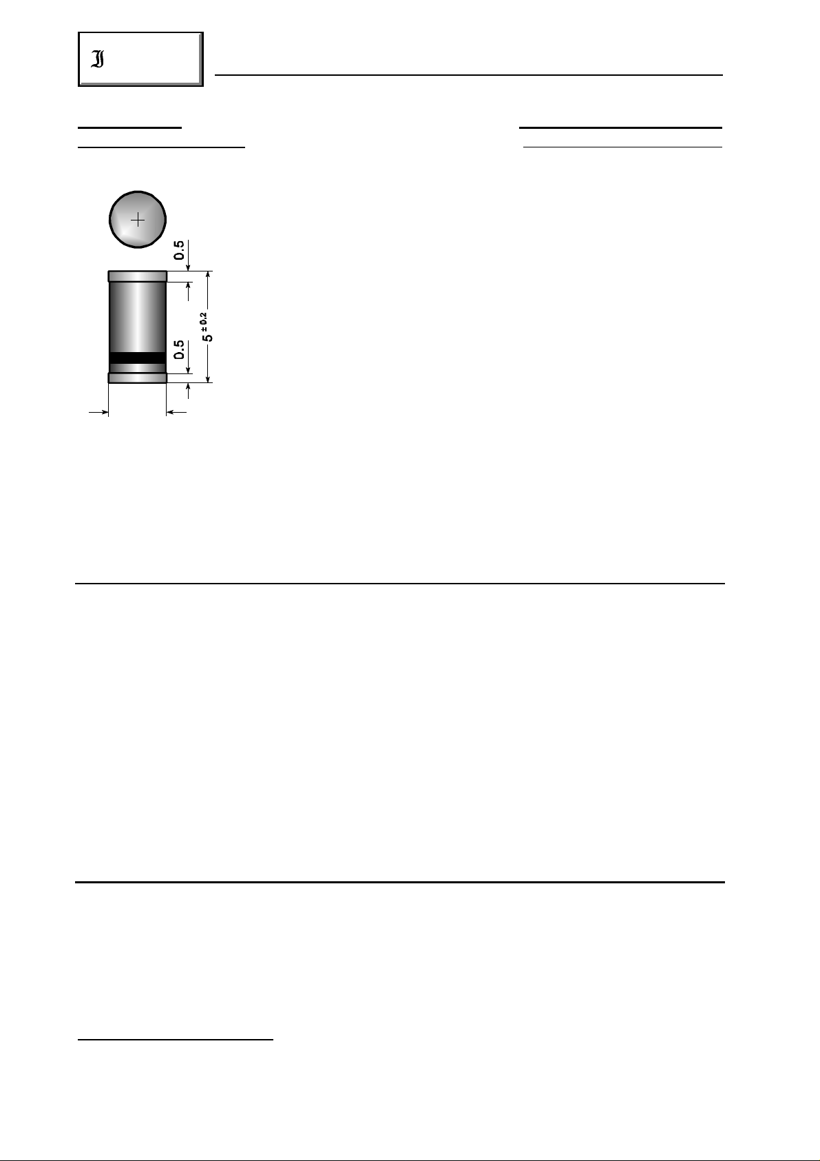
Plastic case MELF DO-213AB
Kunststoffgehäuse MELF
Weight approx. – Gewicht ca. 0.12 g
± 0.1
2.5
Gehäusematerial UL94V-0 klassifiziert
Standard packaging taped and reeled see page 18
Plastic material has UL classification 94V-0
Dimensions / Maße in mm Standard Lieferform gegurtet auf Rolle siehe Seite 18
Maximum ratings Grenzwerte
Power dissipation
Verlustleistung T = 25 °C P 2.0 W )
A tot
Z-voltages see table on next page.
Other voltage tolerances and higher Z-voltages on request.
Arbeitsspannungen siehe Tabelle auf der nächsten Seite.
Andere Toleranzen oder höhere Arbeitsspannungen auf Anfrage.
Operating junction temperature – Sperrschichttemperatur T – 50...+150°C
Storage temperature – Lagerungstemperatur T – 50...+175°C
j
S
1
Characteristics Kennwerte
Thermal resistance junction to ambient air R < 45 K/W )
thA
Wärmewiderstand Sperrschicht – umgebende Luft
1
) Valid, if the temperature of the terminals is kept to 100°C
Gültig, wenn die Temperatur der Anschlüsse auf 100°C gehalten wird
2 2
) Valid, if mounted on P.C. board with 50 mm copper pads at each terminal
Dieser Wert gilt bei Montage auf Leiterplatte mit 50 mm Kupferbelag (Lötpad) an jedem Anschluß
236
2
01.01.99
2

SMZ 1 … SMZ 200 (2 W)
Diotec
Maximum ratings Grenzwerte
Type Zener volt. ) Test current Dynamic resistance Temp.Coeffiz. Reverse volt. Max. Z-current )
Typ Arbeitsspg. ) Meßstrom Inhär.diff. Widerstand of Z-voltage Sperrspanng. Arbeitsstrom )
I = I f=1kHz, I = I …der Z-spg. I = 1 µA T = 45°C
U [V] I [mA] r [ ] 10 [°C] U [V] I [mA]
3
SMZ 1 ) 0.71…0.82 100 0.5 (<1) –26…+16 – 1000
SMZ 3.9 3.7…4.1 100 3.8 (<7) –7…+2 – 410
SMZ 4.3 4.0…4.6 100 3.8 (<7) –7…+3 – 360
SMZ 4.7 4.4…5.0 100 3.8 (<7) –7…+4 – 330
SMZ 5.1 4.8…5.4 100 2 (<5) –6…+5 – 300
SMZ 5.6 5.2…6.0 100 1 (<2) –3…+5 >1.5 275
SMZ 6.2 5.8…6.6 100 1 (<2) –1…+6 >1.5 245
SMZ 6.8 6.4…7.2 100 1 (<2) 0…+7 >2.0 220
SMZ 7.5 7.0…7.9 100 1 (<2) 0…+7 >2.0 200
SMZ 8.2 7.7…8.7 100 1 (<2) +3…+8 >3.5 180
SMZ 9.1 8.5…9.6 50 2 (<4) +3…+8 >3.5 165
SMZ 10 9.4…10.6 50 2 (<4) +5…+9 >5 145
SMZ 11 10.4…11.6 50 4 (<7) +5…+10 >5 135
SMZ 12 11.4…12.7 50 4 (<7) +5…+10 >7 120
SMZ 13 12.4…14.1 50 5 (<10) +5…+10 >7 110
SMZ 15 13.8…15.8 50 5 (<10) +5…+10 >10 98
SMZ 16 15.3…17.1 25 6 (<15) +6…+11 >10 90
SMZ 18 16.8…19.1 25 6 (<15) +6…+11 >10 80
SMZ 20 18.8…21.2 25 6 (<15) +6…+11 >10 72
SMZ 22 20.8…23.3 25 6 (<15) +6…+11 >12 66
SMZ 24 22.8…25.6 25 7 (<15) +6…+11 >12 60
SMZ 27 25.1…28.9 25 7 (<15) +6…+11 >14 53
SMZ 30 28…32 25 8 (<15) +6…+11 >14 48
SMZ 33 31…35 25 8 (<15) +6…+11 >17 44
SMZ 36 34…38 10 21 (<40) +6…+11 >17 40
SMZ 39 37…41 10 21 (<40) +6…+11 >20 37
SMZ 43 40…46 10 24 (<45) +7…+12 >20 33
SMZ 47 44…50 10 24 (<45) +7…+12 >24 30
SMZ 51 48…54 10 25 (<60) +7…+12 >24 27
SMZ 56 52…60 10 25 (<60) +7…+12 >28 25.5
SMZ 62 58…66 10 25 (<80) +8…+13 >28 21
SMZ 68 64…72 10 25 (<80) +8…+13 >34 20
SMZ 75 70…79 10 30 (<100) +8…+13 >34 18
SMZ 82 77…88 10 30 (<100) +8…+13 >41 16
SMZ 91 85…96 5 60 (<200) +9…+13 >41 15
SMZ 100 94…106 5 60 (<200) +9…+13 >50 13
SMZ 110 104…116 5 80 (<250) +9…+13 >50 12
SMZ 120 114…127 5 80 (<250) +9…+13 >60 11
SMZ 130 124…141 5 110 (<300) +9…+13 >60 10
SMZ 150 138…156 5 110 (<300) +9…+13 >75 9
SMZ 160 153…171 5 150 (<350) +9…+13 >75 8.5
SMZ 180 168…191 5 150 (<350) +9…+13 >90 8
SMZ 200 188…212 5 150 (<350) +9…+13 >90 7.5
2 1
2 1
Z Z test Z Z test R A
Z Z test zj VZ R Z
-4
1
) Valid, if the temp. of the terminals is kept to 100°C – Gültig, wenn die Temp. der Anschlüsse auf 100°C gehalten wird
2
) Tested with pulses – Gemessen mit Impulsen
3
) The SMZ 1 is a Si-diode operated in forward direction. Hence, the index of all parameters should be “F”
instead of “Z”. The cathode, indicated by colored ring(s) is to be connected to the negative pole.
Die SMZ 1 ist eine in Durchlaß betriebene Si-Diode. Daher ist bei allen Parametern der Index “F” anstatt “Z”
zu setzen. Der durch Ring(e) gekennzeichnete Anschluß ist mit dem Minuspol zu verbinden.
01.01.99
237
 Loading...