

Diotec Elektronische SMS2100, SMS220, SMS230, SMS240, SMS250 Datasheet
...
Diotec
SMS 220 … SMS 2100
Schottky-Gleichrichter
Surface Mount Schottky-Rectifiers für die Oberflächenmontage
Nominal current – Nennstrom 2 A
Repetitive peak reverse voltage 20…100 V
Periodische Spitzensperrspannung
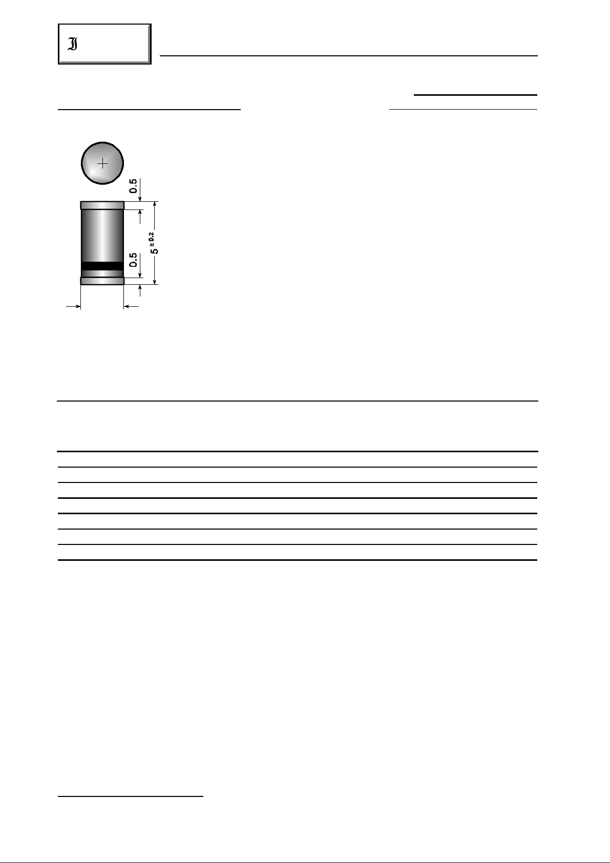
Plastic case MELF DO-213AB
Kunststoffgehäuse MELF
Weight approx. – Gewicht ca. 0.12 g
Plastic material has UL classification 94V-0
Gehäusematerial UL94V-0 klassifiziert
± 0.1
2.5
Standard packaging taped and reeled see page 18
Dimensions / Maße in mm Standard Lieferform gegurtet auf Rolle siehe Seite 18
Maximum ratings Grenzwerte
Type Rep. peak reverse voltage Surge peak reverse voltage Forward voltage *)
Typ Period. Spitzensperrspg. Stoßspitzensperrspannung Durchlaßspannung *)
V [V] V [V] V [V]
RRM RSM F
SMS 220 20 20 < 0.50
SMS 230 30 30 < 0.50
SMS 240 40 40 < 0.50
SMS 250 50 50 < 0.70
SMS 260 60 60 < 0.70
SMS 290 90 80 < 0.79
SMS 2100 100 100 < 0.79
*) I = 2 A, T = 25°C
F j
Max. average forward rectified current, R-load T = 100°C I 2 A
T FAV
Dauergrenzstrom in Einwegschaltung mit R-Last
Repetitive peak forward current f > 15 Hz I 12 A )
FRM
Periodischer Spitzenstrom
1
Rating for fusing, t < 10 ms T = 25°C i t 4,5 A s
A
2 2
Grenzlastintegral, t < 10 ms
Peak fwd. surge current, 50 Hz half sine-wave T = 25°C I 25 A
A FSM
Stoßstrom für eine 50 Hz Sinus-Halbwelle
1
) Valid, if the temperature of the terminals is kept to 100°C
Gültig, wenn die Temperatur der Anschlüsse auf 100°C gehalten wird
228
01.01.99
SMS 220 … SMS 2100
Diotec
Operating junction temperature – Sperrschichttemperatur T – 50...+150°C
Storage temperature – Lagerungstemperatur T – 50...+175°C
j
S
Characteristics Kennwerte
Leakage current – Sperrstrom T = 25°C V = V I < 0.5 mA
Thermal resistance junction to ambient air R < 45 K/W )
j R RRM R
T = 100°C V = V I < 5.0 mA
j R RRM R
thA
Wärmewiderstand Sperrschicht – umgebende Luft
1
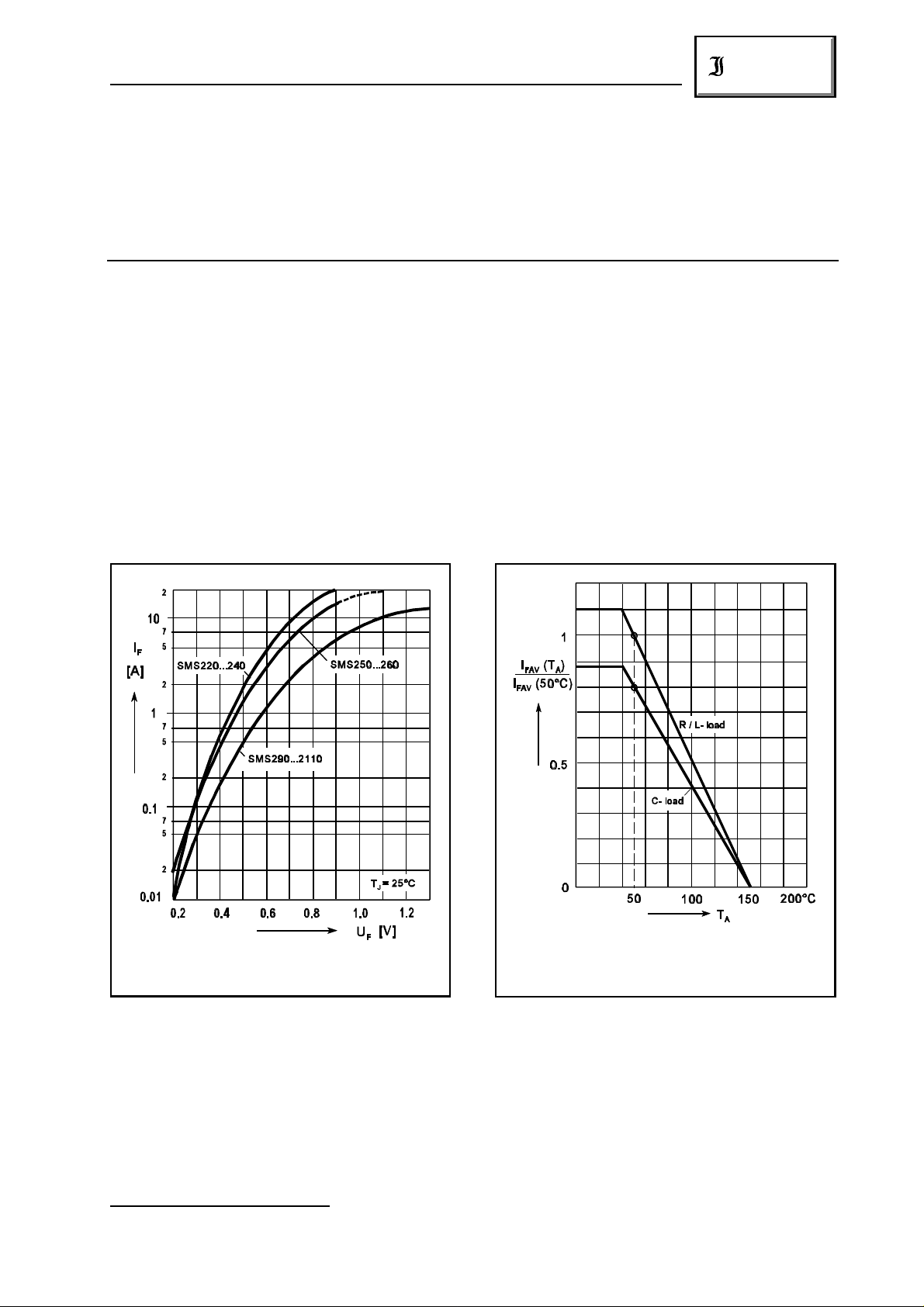
Rated forward current vs. ambient temperature )
Forward characteristics (typical values)
Durchlaßkennlinien (typische Werte)
1 2
) Valid, if mounted on P.C. board with 50 mm copper pads at each terminal
Dieser Wert gilt bei Montage auf Leiterplatte mit 50 mm Kupferbelag (Lötpad) an jedem Anschluß
01.01.99
2
Dauergrenzstrom in Einwegschaltung in Abh.
von der Umgebungstemperatur )
1
1
229
 Loading...