

Diotec Elektronische S125, S250, S380, S40, S500 Datasheet
...
Diotec
S40 … S500
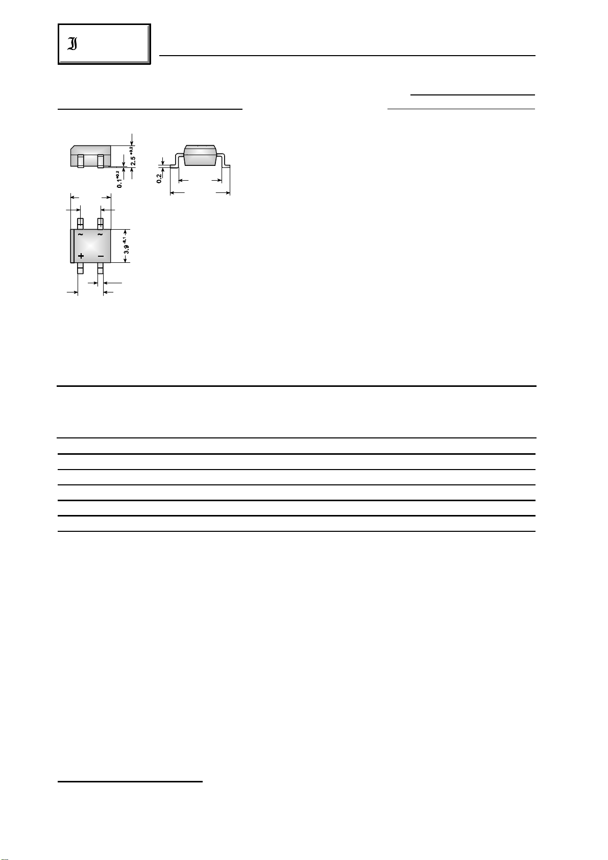
Si-Brückengleichrichter
Surface Mount Si-Bridge Rectifiers für die Oberflächenmontage
Nominal current – Nennstro m 0.8 A
Alternating input voltage 40…500 V
Eingangswechselspannung
Plastic case – Kunststoffgehäuse 4.7 x 3.9 x 2.4 [mm]
4.7
2.54
+0.2
5.1
+0.2
-0.1
6.5
Weight approx. – Gewicht ca. 0.4 g
Plastic material has UL classification 94V-0
0.7
3.24
Gehäusematerial UL94V-0 klassifiziert
Standard packaging taped and reeled see page 18
Dimensions / Maße in mm
Standard Lieferform gegurtet auf Rolle siehe Seite 18
Ma ximum rati ngs Grenzwerte
Type Alternating input voltage Rep. peak reverse volt. ) Surge peak reverse volt. )
Typ Eingangswechselspanng. Period. Spitzensperrspg. ) Stoßspitzensperrspanng. )
V [V] V [V] V [V]
VRMS RRM RSM
11
11
S40 40 80 100
S80 80 160 200
S125 125 250 400
S250 250 500 800
S380 380 800 1000
S500 500 1000 1300
Repetitive peak forward current f > 15 Hz I 10 A )
FRM
Periodischer Spitzenstrom
Rating for fusing, t < 10 ms T = 25°C i t 8 A s
A
22
Grenzlastintegral, t < 10 ms
Peak fwd. surge current, 50 Hz half sine-wave T = 25°C I 40 A
A FSM
Stoßstrom für eine 50 Hz Sinus-Halbwelle
2
Operating junction temperature – Sperrschichttemperatur T – 50...+150°C
Storage temperature – Lagerungstemperatur T – 50...+150°C
1
) Valid for one branch – Gültig für einen Brückenzweig
2
) Valid, if the temperature of the terminals is kept to 100°C
Gültig, wenn die Temperatur der Anschlüsse auf 100°C gehalten wird
242
j
S
01.01.99
S40 … S500
Diotec
Characteristics Kennwerte
Max. average fwd. rectified current T = 50°C R-load I 0.8 A )
Dauergrenzstrom C-load I 0.6 A )
Forward voltage – Durchlaßspannung T = 25°C I = 0.8 A V < 1.2 V )
Leakage current – Sperrstrom T = 25°C V = V I < 10 µA
Thermal resistance junction to ambient air R < 60 K/W )
A FAV
FAV
j F F
j R RRM R
thA
Wärmewiderstand Sperrschicht – umgebende Luft
Type Max. admissible load capacitor Min. required protective resistor
Typ Max. zulässiger Ladekondensator Min. erforderl. Schutzwiderstand
C [µF] R [ ]
L t
S40 5000 0.8
S80 2500 1.6
S125 1500 2.5
S250 800 5.0
S380 600 8.5
S500 400 10
2
2
1
2
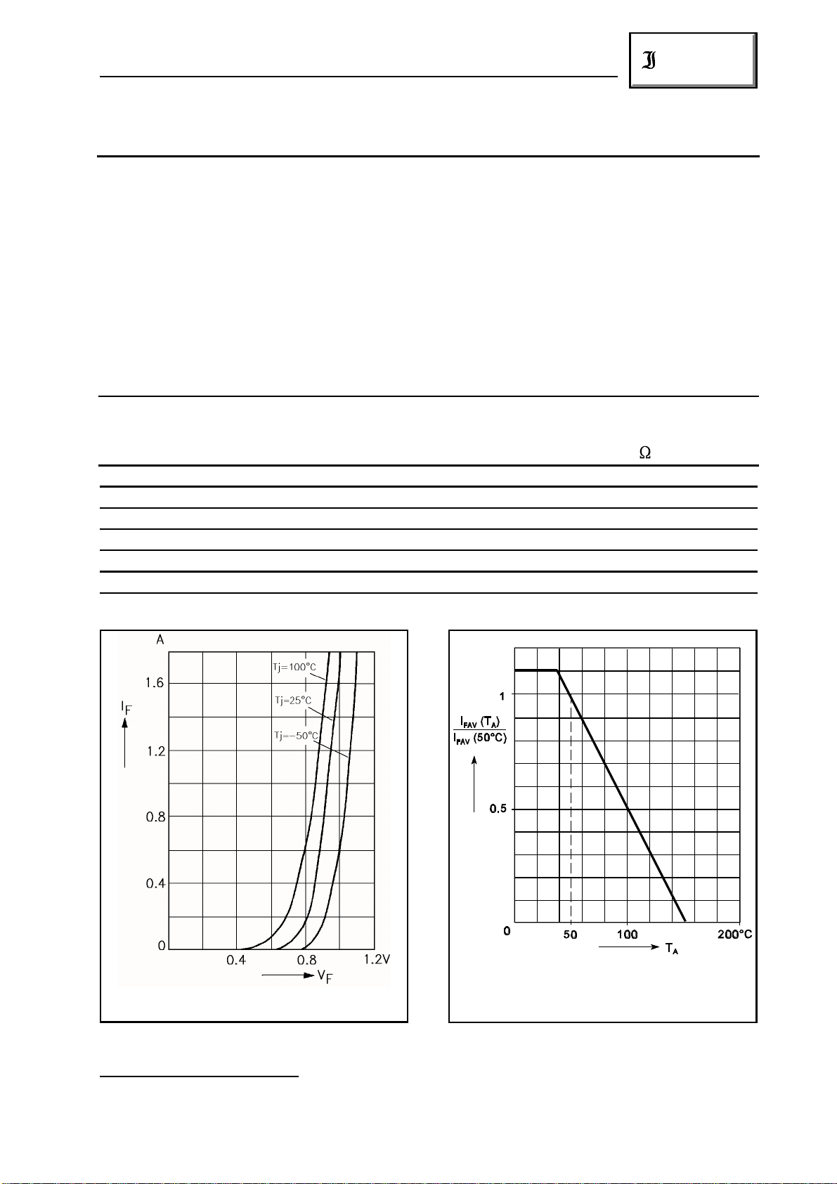
Forward characteristics (typical values) )
Durchlaßkennlinien (typische Werte) )
1
) Valid for one branch – Gültig für einen Brückenzweig
2 2
) Valid, if mounted on P.C. board with 25 mm copper pads at each terminal
Dieser Wert gilt bei Montage auf Leiterplatte mit 25 mm Kupferbelag (Lötpad) an jedem Anschluß
01.01.99
1
1
2
Rated forward current vs. ambient temperature )
Zulässiger Richtstrom in Abhängigkeit
von der Umgebungstemperatur )
2
2
243
 Loading...