

Diotec Elektronische KBU12M, KBU12K, KBU12J, KBU12G, KBU12A Datasheet
...
Diotec
KBU 12A ... KBU 12M
Silicon-Bridge Rectifiers Silizium-Brückengleichrichter
5.7
±0.2
23.5
±0.2
4
Nominal current – Nennstrom 12.0 A
2
Alternating input voltage 35…700 V
Eingangswechselspannung
3.35
1.2
5.08
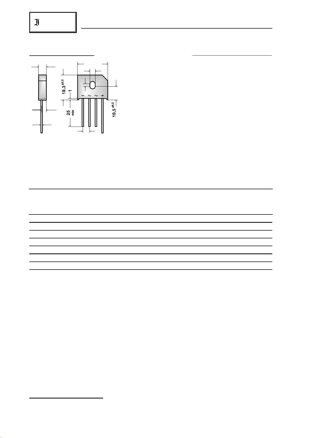
Plastic case – Kunststoffgehäuse 23.5 x 7 x 19.3 [mm]
Weight approx. – Gewicht ca. 8 g
Plastic material has UL classification 94V-0
Gehäusematerial UL94V-0 klassifiziert
Dimensions / Maße in mm
Standard packaging: bulk
Standard Lieferform: lose im Karton
Ma ximum rati ngs Grenzwerte
Type Alternating input volt. Rep. peak reverse volt. ) Surge peak reverse volt. )
Typ Eingangswechselspg. Period. Spitzensperrspg. ) Stoßspitzensperrspanng. )
V [V] V [V] V [V]
VRMS RRM RSM
11
11
KBU 12A 35 50 80
KBU 12B 70 100 130
KBU 12D 140 200 250
KBU 12G 280 400 450
KBU 12J 420 600 700
KBU 12K 560 800 1000
KBU 12M 700 1000 1200
Repetitive peak forward current f > 15 Hz I 60 A )
FRM
2
Periodischer Spitzenstrom
Rating for fusing, t < 8.3 ms T = 25°C i t 375 A s
A
22
Grenzlastintegral, t < 8.3 ms
Peak fwd. surge current, 60 Hz half sine-wave T = 25°C I 300 A
A FSM
Stoßstrom für eine 60 Hz Sinus-Halbwelle
Operating junction temperature – Sperrschichttemperatur T – 50…+150°C
Storage temperature – Lagerungstemperatur T – 50…+150°C
j
S
Admissible torque for mounting M 4 9 ± 10% lb.in.
Zulässiges Anzugsdrehmoment 1 ± 10% Nm
1
) Valid for one branch – Gültig für einen Brückenzweig
2
) Valid, if leads are kept at ambient temperature at a distance of 10 mm from case
Gültig, wenn die Anschlußdrähte in 10 mm Abstand von Gehäuse auf Umgebungstemperatur gehalten werden
282
01.01.99
KBU 12A ... KBU 12M
Diotec
Characteristics Kennwerte
Max. fwd. current without cooling fin T = 50°C R-load I 8.4 A )
Dauergrenzstrom ohne Kühlblech C-load I 7.4 A )
Max. current with cooling fin 300 cm T = 50°C R-load I 12.0 A
2
Dauergrenzstrom mit Kühlblech 300 cm C-load I 9.6 A
Forward voltage – Durchlaßspannung T = 25°C I = 12 A V < 1.0 V )
Leakage current – Sperrstrom T = 25°C V = V I < 10 µA
Thermal resistance junction to case R < 3.3 K/W
A FAV
A FAV
2
j F F
j R RRM R
FAV
FAV
thC
Wärmewiderstand Sperrschicht – Gehäuse
Type Max. admissible load capacitor Min. required protective resistor
Typ Max. zulässiger Ladekondensator Min. erforderl. Schutzwiderstand
C [µF] R [ ]
L t
KBU 12A 20000 0.2
KBU 12B 10000 0.4
KBU 12D 5000 0.8
KBU 12G 2500 1.6
KBU 12J 1500 2.4
KBU 12K 1000 3.2
KBU 12M 800 4.0
1
1
2
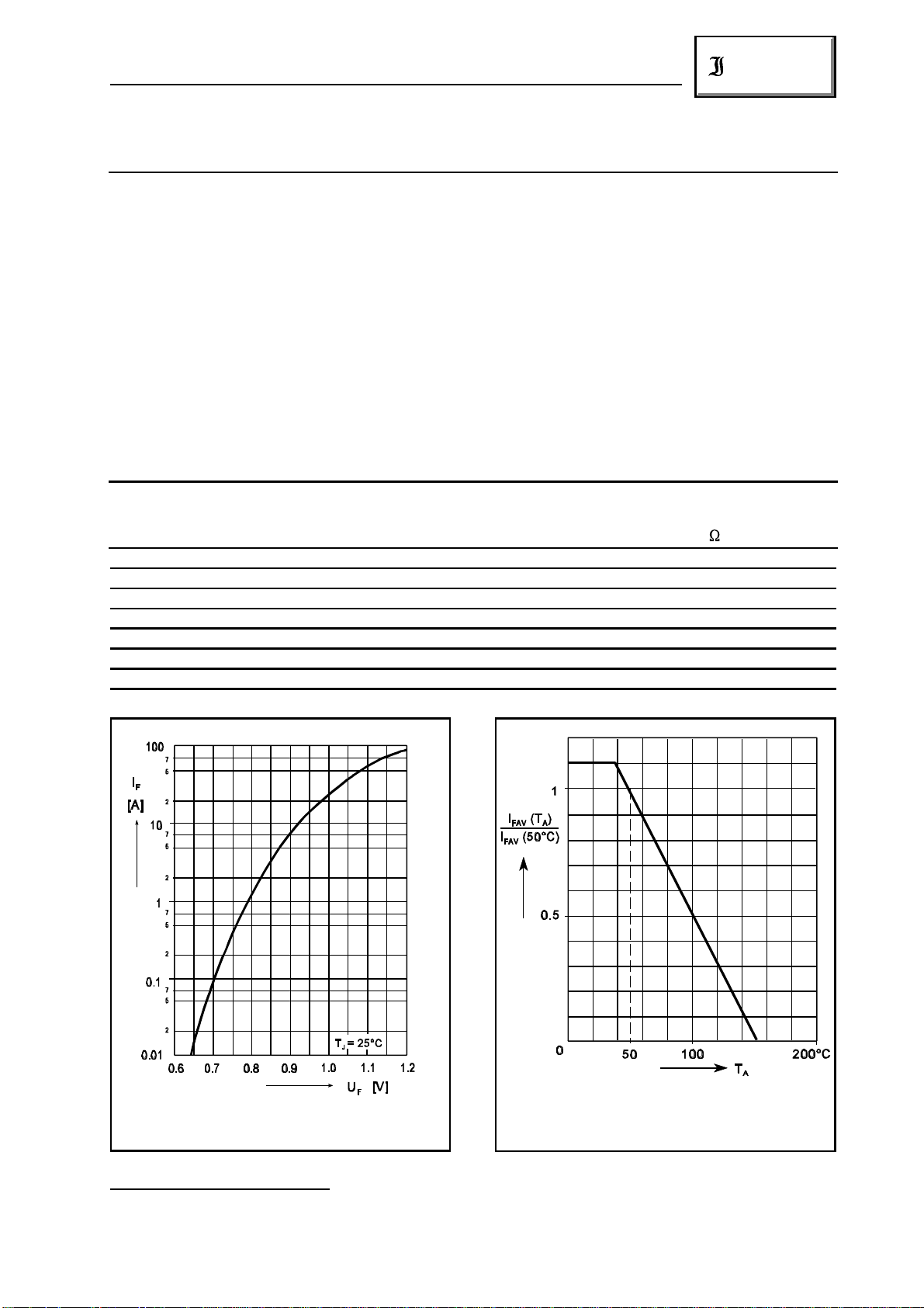
Forward characteristic (typical values) )
Durchlaßkennlinie (typische Werte) )
1
) Valid, if leads are kept at ambient temperature at a distance of 10 mm from case
Gültig, wenn die Anschlußdrähte in 10 mm Abstand von Gehäuse auf Umgebungstemperatur gehalten werden
2
) Valid for one branch – Gültig für einen Brückenzweig
2
2
Zulässiger Richtstrom in Abhängigkeit
von der Umgebungstemperatur
01.01.99
Rated forward current vs. ambient temperature
283
 Loading...