

Diotec Elektronische KBPC802, KBPC810, KBPC806, KBPC804, KBPC801 Datasheet
...
Diotec
KBPC 800 … KBPC 810
Silicon-Bridge Rectifiers Silizium-Brückengleichrichter
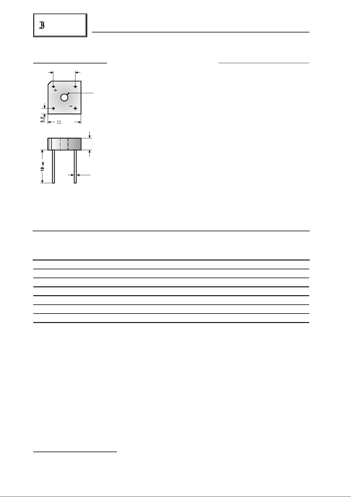
±0.3
12.7
Nominal current – Nennstrom 8.0 A
Ø 3.9
Alternating input voltage 35…700 V
Eingangswechselspannung
19
±0.2
Plastic case 19 x 19 x 6.8 [mm]
Kunststoffgehäuse
6.8
±0.2
Weight approx. – Gewicht ca. 5,5 g
Plastic material has UL classification 94V-0
Ø 1.2
Gehäusematerial UL94V-0 klassifiziert
Standard packaging: bulk
Dimensions / Maße in mm Standard Lieferform: lose im Karton
Maximum ratings Grenzwerte
Type Alternating input volt. Rep. peak reverse volt. ) Surge peak reverse volt. )
Typ Eingangswechselspg. Period. Spitzensperrspg. ) Stoßspitzensperrspanng. )
V [V] V [V] V [V]
VRMS RRM RSM
1 1
1 1
KBPC 800 35 50 80
KBPC 801 70 100 130
KBPC 802 140 200 250
KBPC 804 280 400 450
KBPC 806 420 600 700
KBPC 808 560 800 1000
KBPC 810 700 1000 1200
Repetitive peak forward current f > 15 Hz I 40 A )
FRM
Periodischer Spitzenstrom
Rating for fusing, t < 8.3 ms T = 25°C i t 93 A s
A
2 2
Grenzlastintegral, t < 8.3 ms
Peak fwd. surge current, 60 Hz half sine-wave T = 25°C I 150 A
A FSM
Stoßstrom für eine 60 Hz Sinus-Halbwelle
Operating junction temperature – Sperrschichttemperatur T – 50…+150°C
Storage temperature – Lagerungstemperatur T – 50…+150°C
1
) Valid for one branch – Gültig für einen Brückenzweig
2
) Valid, if leads are kept at ambient temperature at a distance of 10 mm from case
Gültig, wenn die Anschlußdrähte in 10 mm Abstand von Gehäuse auf Umgebungstemperatur gehalten werden
286
j
S
01.01.99
2
KBPC 800 … KBPC 810
Diotec
Characteristics Kennwerte
Max. fwd. current without cooling fin T = 50°C R-load I 5.0 A )
Dauergrenzstrom ohne Kühlblech C-load I 4.0 A )
Max. current with cooling fin 300 cm T = 50°C R-load I 8.0 A
2
Dauergrenzstrom mit Kühlblech 300 cm C-load I 6.4 A
Forward voltage – Durchlaßspannung T = 25°C I = 4 A V < 1.2 V )
Leakage current – Sperrstrom T = 25°C V = V I < 10 µA
Thermal resistance junction to case R < 3.3 K/W
A FAV
A FAV
2
j F F
j R RRM R
FAV
FAV
thC
Wärmewiderstand Sperrschicht – Gehäuse
Admissible torque for mounting M 4 9 ± 10% lb.in.
Zulässiges Anzugsdrehmoment 1 ± 10% Nm
1
1
2
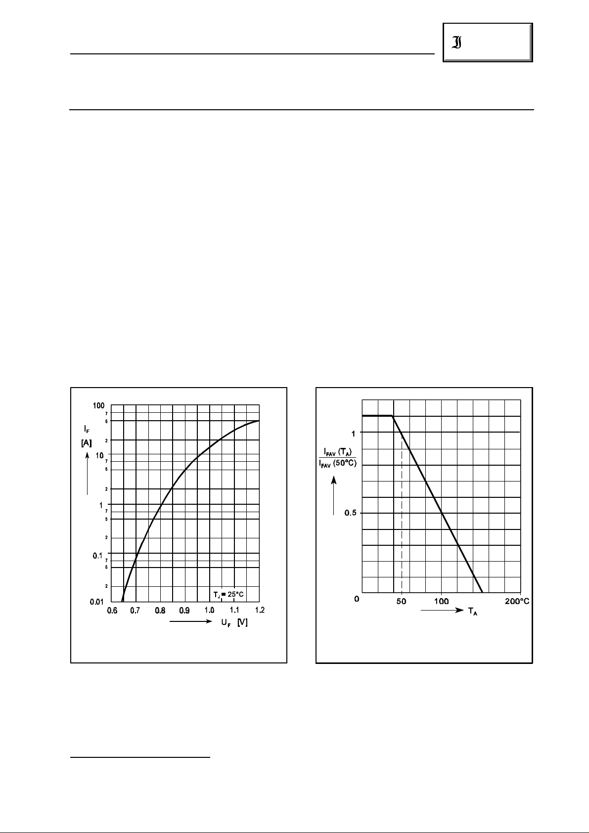
Forward characteristic (typical values) )
Durchlaßkennlinie (typische Werte) )
1
) Valid, if leads are kept at ambient temperature at a distance of 10 mm from case
Gültig, wenn die Anschlußdrähte in 10 mm Abstand von Gehäuse auf Umgebungstemperatur gehalten werden
2
) Valid for one branch – Gültig für einen Brückenzweig
2
2
Zulässiger Richtstrom in Abhängigkeit
von der Umgebungstemperatur
01.01.99
Rated forward current vs. ambient temperature
287
 Loading...