

Diotec Elektronische KBPC5006F, KBPC5012F, KBPC5008F, KBPC5004F, KBPC5010F Datasheet
...
Diotec
KBPC 5000 … KBPC 5012
Silicon-Bridge Rectifiers Silizium-Brückengleichrichter
Type “F” Nominal current – Nennstrom 50 A
6.35
±0.1
0.8
±0.05
Alternating input voltage
Eingangswechselspannung 35…1000 V
Metal case (Index “M”) or
Plastic case with alu-bottom (Index “P”)
7.3
±0.2
Metallgehäuse (Index “M”) oder
16.6
±0.5
Kunststoffgehäuse mit Alu-Boden (Index “P”)
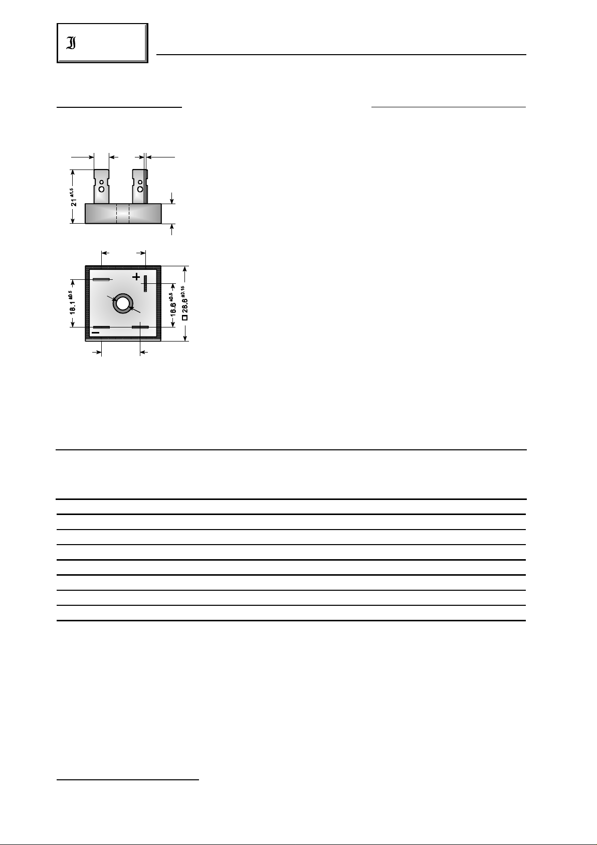
Dimensions – Abmessungen 28.6 x 28.6 x 7.3 [mm]
Weight approx. – Gewicht ca.23 g
±0.1
Ø 5.2
Casting compound has UL classification 94V-0
14.3
±0.5
Vergußmasse UL94V-0 klassifiziert
Standard packaging: bulk
Dimensions / Maße in mm Standard Lieferform: lose im Karton
Maximum ratings Grenzwerte
Type Alternating input volt. Rep. peak reverse volt. ) Surge peak reverse volt. )
Typ Eingangswechselspg. Period. Spitzensperrspg. ) Stoßspitzensperrspanng. )
V [V] V [V] V [V]
VRMS RRM RSM
1 1
1 1
KBPC 5000 F 35 50 70
KBPC 5001 F 70 100 130
KBPC 5002 F 140 200 250
KBPC 5004 F 280 400 450
KBPC 5006 F 420 600 700
KBPC 5008 F 560 800 1000
KBPC 5010 F 700 1000 1200
KBPC 5012 F 800 1200 1300
Repetitive peak forward current f > 15 Hz I 90 A )
FRM
Periodischer Spitzenstrom
Rating for fusing, t < 8.3 ms T = 25°C i t 800 A s
A
2 2
Grenzlastintegral, t < 8.3 ms
2
1
) Valid for one branch – Gültig für einen Brückenzweig
2
) Valid, if the temperature of the case is kept to 120°C – Gültig, wenn die Gehäusetemperatur auf 120°C gehalten wird
302
01.01.99
KBPC 5000 … KBPC 5012
Diotec
Peak fwd. surge current, 60 Hz half sine-wave T = 25°C I 450 A
A FSM
Stoßstrom für eine 60 Hz Sinus-Halbwelle
Operating junction temperature – Sperrschichttemperatur T – 50…+150°C
Storage temperature – Lagerungstemperatur T – 50…+150°C
j
S
Characteristics Kennwerte
Max. current with cooling fin 300 cm T = 50°C R-load I 50.0 A
Dauergrenzstrom mit Kühlblech 300 cm C-load I 46.0 A
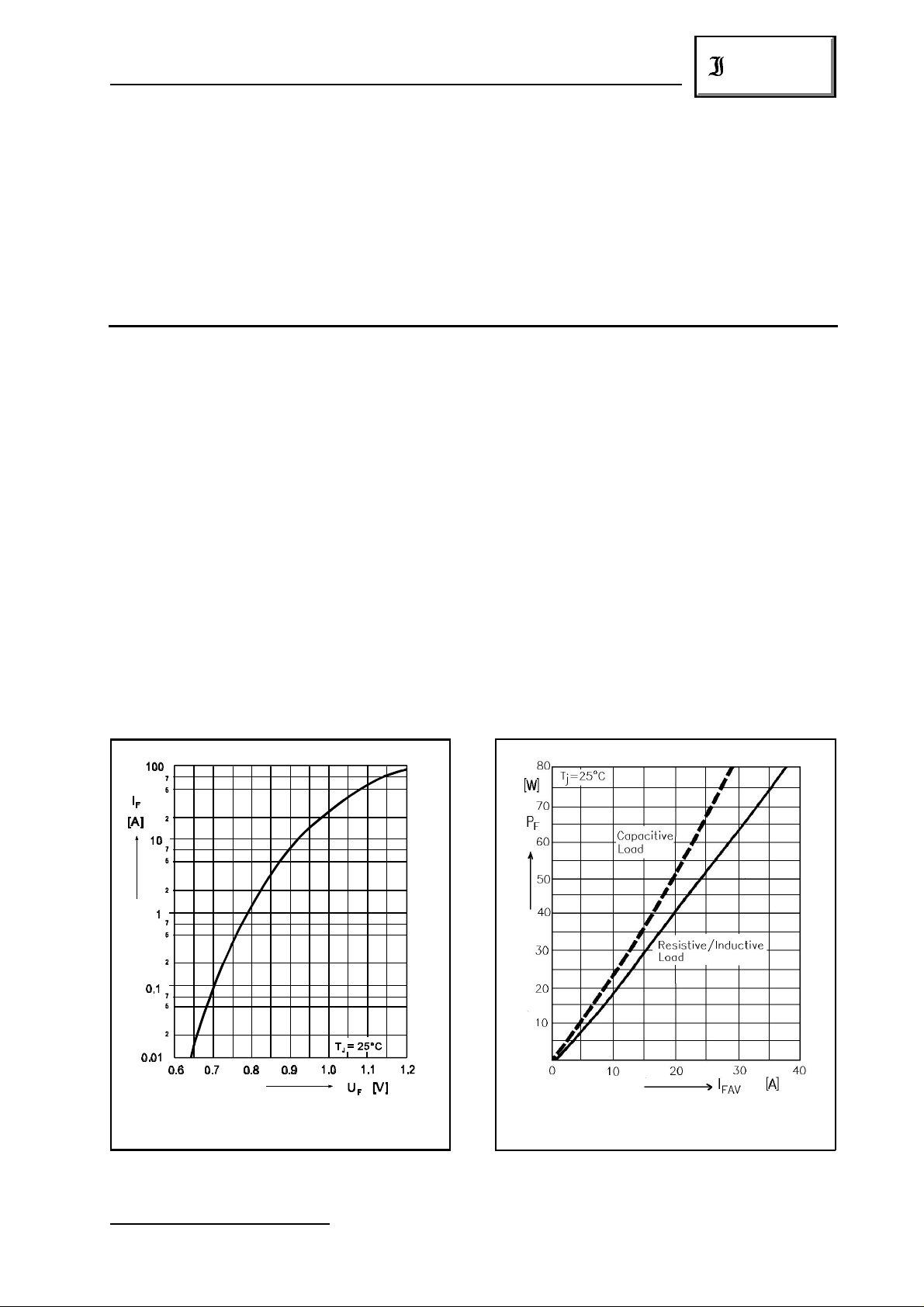
Forward voltage – Durchlaßspannung T = 25°C I = 25 A V < 1.1 V )
Leakage current – Sperrstrom T = 25°C V = V I < 25 µA
Isolation voltage terminals to case V >2500 V
2
A FAV
2
j F F
j R RRM R
FAV
ISO
Isolationsspannung Anschlüsse zum Gehäuse
Thermal resistance junction to case R < 2.0 K/W
thC
Wärmewiderstand Sperrschicht – Gehäuse
1
Admissible torque for mounting 10-32 UNF 18 ± 10% lb.in.
Zulässiges Anzugsdrehmoment M 5 2 ± 10% Nm
Forward characteristic (typical values) )
Durchlaßkennlinie (typische Werte) )
1
) Valid for one branch – Gültig für einen Brückenzweig
01.01.99
1
1
Maxium power dissipation
Maximale Verlustleistung
303
 Loading...