

Page 1
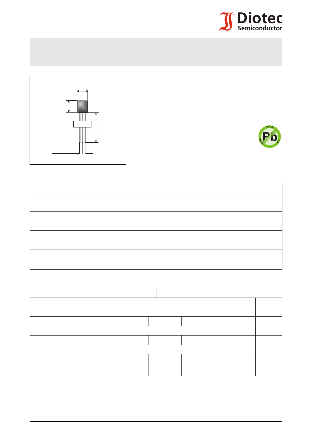
MPSA44-BK
2 x 1.27
E
B C
4.6
±0.1
4.6
±0.1
min 12.5
MPSA44-BK
NPN
High voltage Si-epitaxial planar transistors
Hochspannungs-Si-Epitaxial Planar-Transistoren
NPN
Version 2011-07-07
Power dissipation
625 mW
Verlustleistung
Plastic case
Kunststoffgehäuse
Weight approx.
TO-92
(10D3)
0.18 g
Gewicht ca.
Plastic material has UL classification 94V-0
Gehäusematerial UL94V-0 klassifiziert
Special packaging bulk
Sonder-Lieferform Schüttgut
Dimensions / Maße [mm]
Maximum ratings (TA = 25°C) Grenzwerte (TA = 25°C)
MPSA44
Collector-Emitter-volt. - Kollektor-Emitter-Spannung B open V
Collector-Base-voltage - Kollektor-Basis-Spannung E open V
Emitter-Base-voltage - Emitter-Basis-Spannung C open V
Power dissipation – Verlustleistung P
Collector current – Kollektorstrom (dc) I
Junction temperature – Sperrschichttemperatur
Storage temperature – Lagerungstemperatur
T
T
CEO
CBO
EBO
tot
C
j
S
400 V
500 V
6 V
625 mW 1)
300 mA
-55...+150°C
-55…+150°C
Characteristics (Tj = 25°C) Kennwerte (Tj = 25°C)
Min. Typ. Max.
Collector-Base cutoff current – Kollektorreststrom
IE = 0, VCB = 400 V MPSA44 I
CB0
– – 100 nA
Emitter-Base cutoff current – Emitterreststrom
IB = 0, VEB = 4 V MPSA44 I
EB0
– – 100 nA
Collector saturation voltage – Kollektor-Sättigungsspannung 2)
IC = 1 mA, IB = 0.1 mA
IC = 10 mA, IB = 1 mA
IC = 50 mA, IB = 5 mA
1 Valid, if leads are kept at ambient temperature at a distance of 2 mm from the case
Gültig, wenn die Anschlussdrähte in 2 mm Abstand vom Gehäuse auf Umgebungstemperatur gehalten werden
2 Tested with pulses tp = 300 µs, duty cycle ≤ 2% – Gemessen mit Impulsen tp = 300 µs, Schaltverhältnis ≤ 2%
© Diotec Semiconductor AG http://www.diotec.com/ 1
MPSA44 V
V
V
CEsat
CEsat
CEsat
– – 400 mV
500 mV
750 mV
Page 2
MPSA44-BK
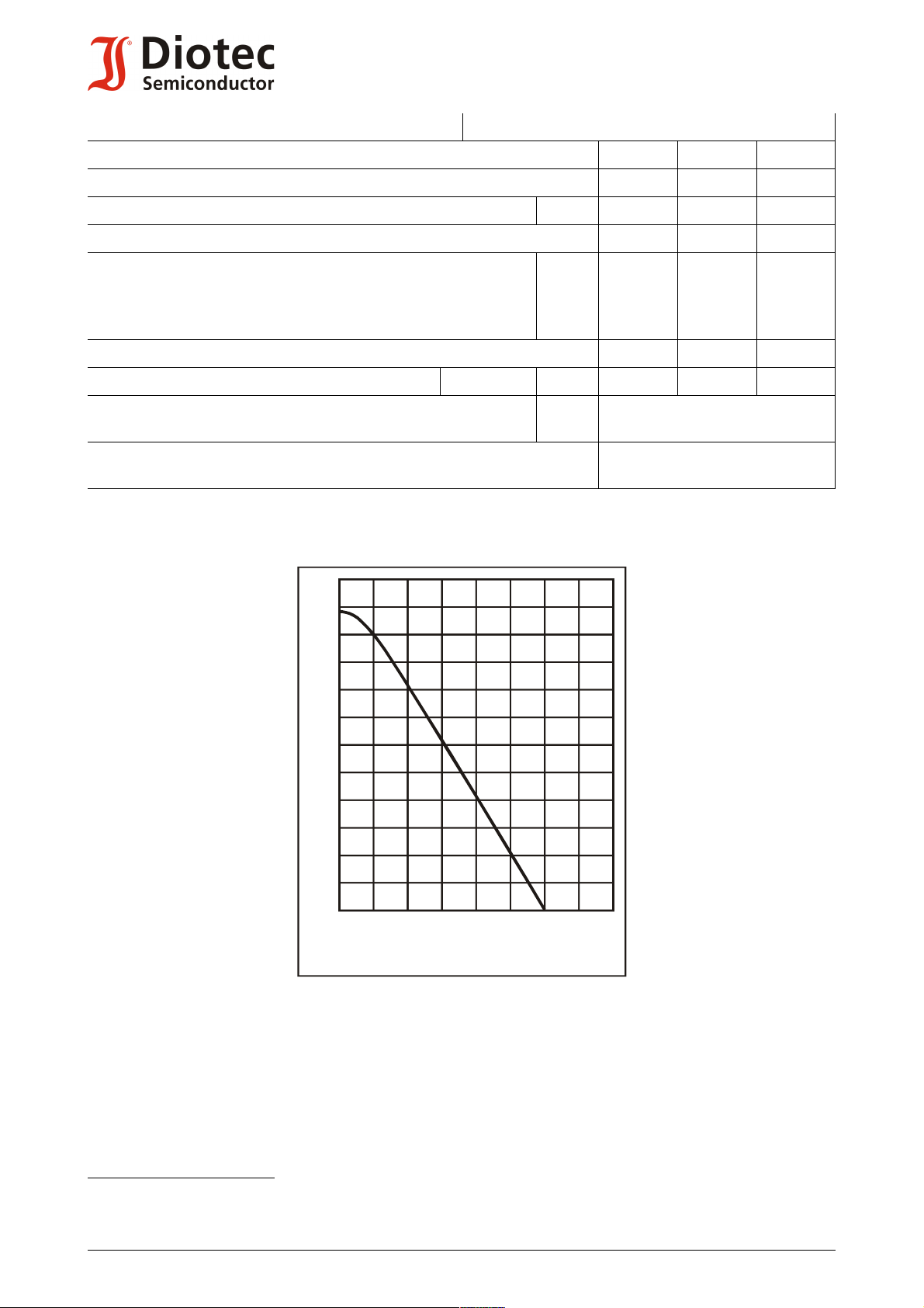
[%]
P
tot
120
100
80
60
40
20
0
[°C]
T
A
150100
50
0
Power dissipation versus ambient temperature )
Verlustleistung in Abh. von d. Umgebungstemp. )
1
1
Characteristics (Tj = 25°C) Kennwerte (Tj = 25°C)
Min. Typ. Max.
Base saturation voltage – Basis-Sättigungsspannung 1)
IC = 10 mA, IB = 1 mA V
DC current gain – Kollektor-Basis-Stromverhältnis
V
= 10 V, IC = 1 mA
CE
VCE = 10 V, IC = 10 mA
VCE = 10 V, IC = 50 mA
VCE = 10 V, IC = 100 mA
Collector-Base Capacitance – Kollektor-Basis-Kapazität
VCB = 20 V, IE = ie = 0, f = 1 MHz MPSA44 C
Thermal resistance junction – ambient air
Wärmewiderstand Sperrschicht – umgebende Luft
Recommended complementary PNP transistors
Empfohlene komplementäre PNP-Transistoren
h
h
h
h
R
BEsat
FE
FE
FE
FE
CB0
thA
– – 750 mV
40
50
45
40
–
200
–
–
–
–
–
–
– – 7pF
< 200 K/W 2)
MPSA94
1 Tested with pulses tp = 300 µs, duty cycle ≤ 2% – Gemessen mit Impulsen tp = 300 µs, Schaltverhältnis ≤ 2%
2 Valid, if leads are kept at ambient temperature at a distance of 2 mm from the case
Gültig, wenn die Anschlussdrähte in 2 mm Abstand vom Gehäuse auf Umgebungstemperatur gehalten werden
2 http://www.diotec.com/ © Diotec Semiconductor AG
 Loading...