

Page 1
GBU8A ... GBU8M
Pb
E
L
V
W
E
E
E
R
o
H
S
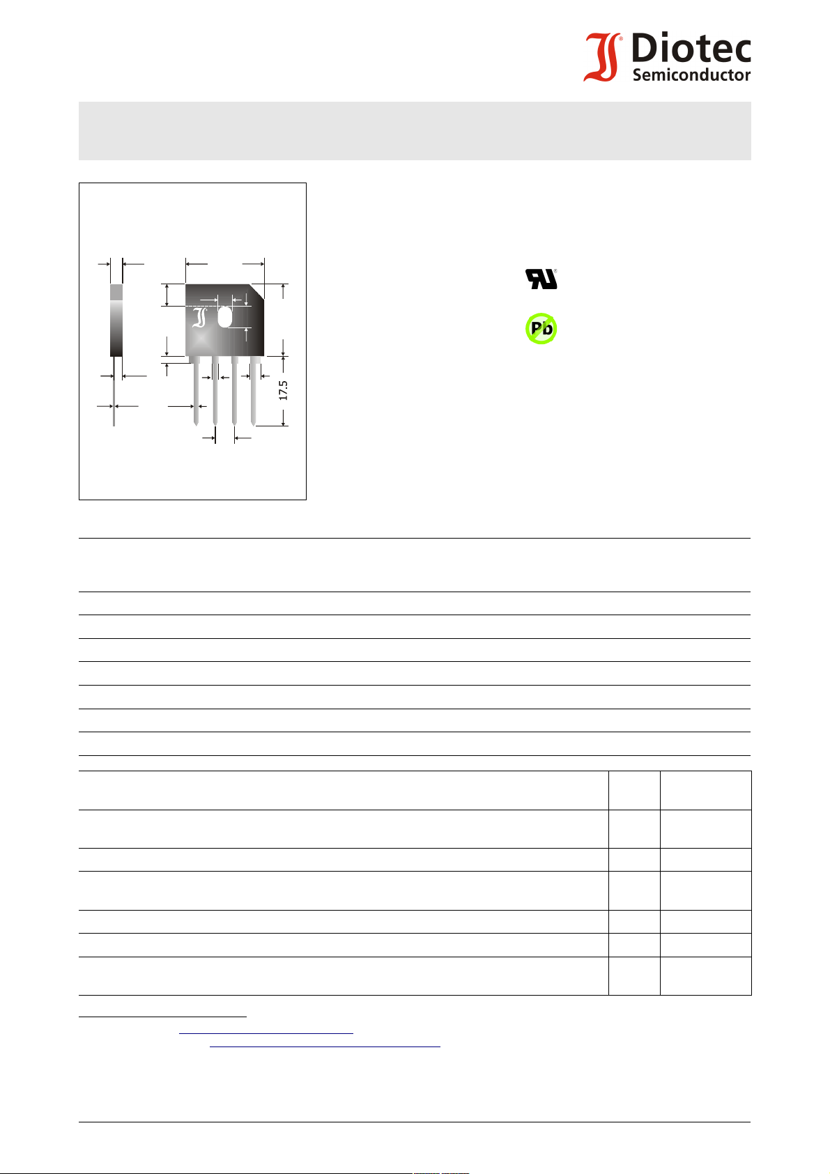
21.5
±0.7
3.6
±0.2
5.08
1.1
+0.2
1.7
±0.1
5.6
0.5
+0.1
2.2
3.4
±0.1
5.3
+0.5
18.2
±0.3
GBU ...
+
–
~
~
1.8
+0.7
- 0.1
1.8
+0.2
Einphasen-Brückengleichrichter
Version 2019-11-25
Dimensions - Maße [mm]
GBU8A ... GBU8M
Single Phase Bridge Rectifier
Typical Application
GBU
50/60 Hz Mains Rectification,
Power Supplies
Commercial grade 1)
Features
UL recognized, File E175067
For free-standing or
heatsink assembly
Compliant to RoHS, REACH,
Conflict Minerals 1)
Mechanical Data 1) Mechanische Daten 1)
Bulk in cardboard trays
Suffix -T: packed in tubes
Weight approx. 3.8 g Gewicht ca.
Case material UL 94V-0 Gehäusematerial
Solder & assembly conditions 260°C/10s Löt- und Einbaubedingungen
I
= 8 A
FAV
VF< 1.0 V
T
= 150°C
jmax
1000
20/1000
MSL N/A
V
= 50...1000 V
RRM
I
= 180/200 A
FSM
trr~ 1500 ns
Typische Anwendung
50/60 Hz Netzgleichrichtung,
Stromversorgungen
Standardausführung 1)
Besonderheit
UL-anerkannt, Liste E175067
Montage freistehend oder
auf Kühlkörper
Konform zu RoHS, REACH,
Konfliktmineralien 1)
Lose in Einlagekartons
Suffix -T: verpackt in Stangen
Maximum ratings 2) Grenzwerte 2)
Type
Typ
Max. alternating input voltage
Max. Eingangswechselspannung
V
[V] 3)
VRMS
Repetitive peak reverse voltage
Periodische Spitzensperrspannung
V
[V] 4)
RRM
GBU8A 35 50
GBU8B 70 100
GBU8D 140 200
GBU8G 280 400
GBU8J 420 600
GBU8K 560 800
GBU8M 700 1000
Max. rectified output current free standing
Dauergrenzstrom am Brückenausgang freistehend
Max. rectified current with cooling fin 300 cm
Dauergrenzstrom mit Kühlblech 300 cm
2
2
Repetitive peak forward current – Periodischer Spitzenstrom f > 15 Hz I
Peak forward surge current
Stoßstrom in Fluss-Richtung
R-load
C-load
R-load
C-load
Half sine-wave
Sinus-Halbwelle
TA = 40°C I
TC = 100°C I
50 Hz (10 ms)
60 Hz (8.3 ms)
FAV
FAV
FRM
I
FSM
Rating for fusing – Grenzlastintegral t < 10 ms i2t 162 A2s
Junction/storage temperature – Sperrschicht-/Lagerungstemperatur T
Admissible mounting torque
Zulässiges Anzugsdrehmoment
1 Please note the detailed information on our website or at the beginning of the data book
2 TA = 25°C unless otherwise specified – TA = 25°C wenn nicht anders angegeben
3 Eventual superimposed voltage peaks must not exceed V
4 Valid per diode – Gültig pro Diode
5 Leads kept at ambient temperature in 5 mm distance from case – Anschlussdrähte in 5 mm vom Gehäuse auf TA gehalten
1 http://www.diotec.com/ © Diotec Semiconductor AG
– Evtl. überlagerte Spannungsspitzen dürfen V
RRM
Bitte beachten Sie die detaillierten Hinweise auf unserer Internetseite bzw. am Anfang des Datenbuches
M3
RRM
-50...+150°C
j/S
9 ± 10% lb.in.
1 ± 10% Nm
nicht überschreiten
5.6 A 5)
4.5 A 5)
8.0 A
6.4 A
36 A 5)
180 A
200 A
Page 2
GBU8A ... GBU8M
10
10
10
1
10
3
2
-1
[A]
I
F
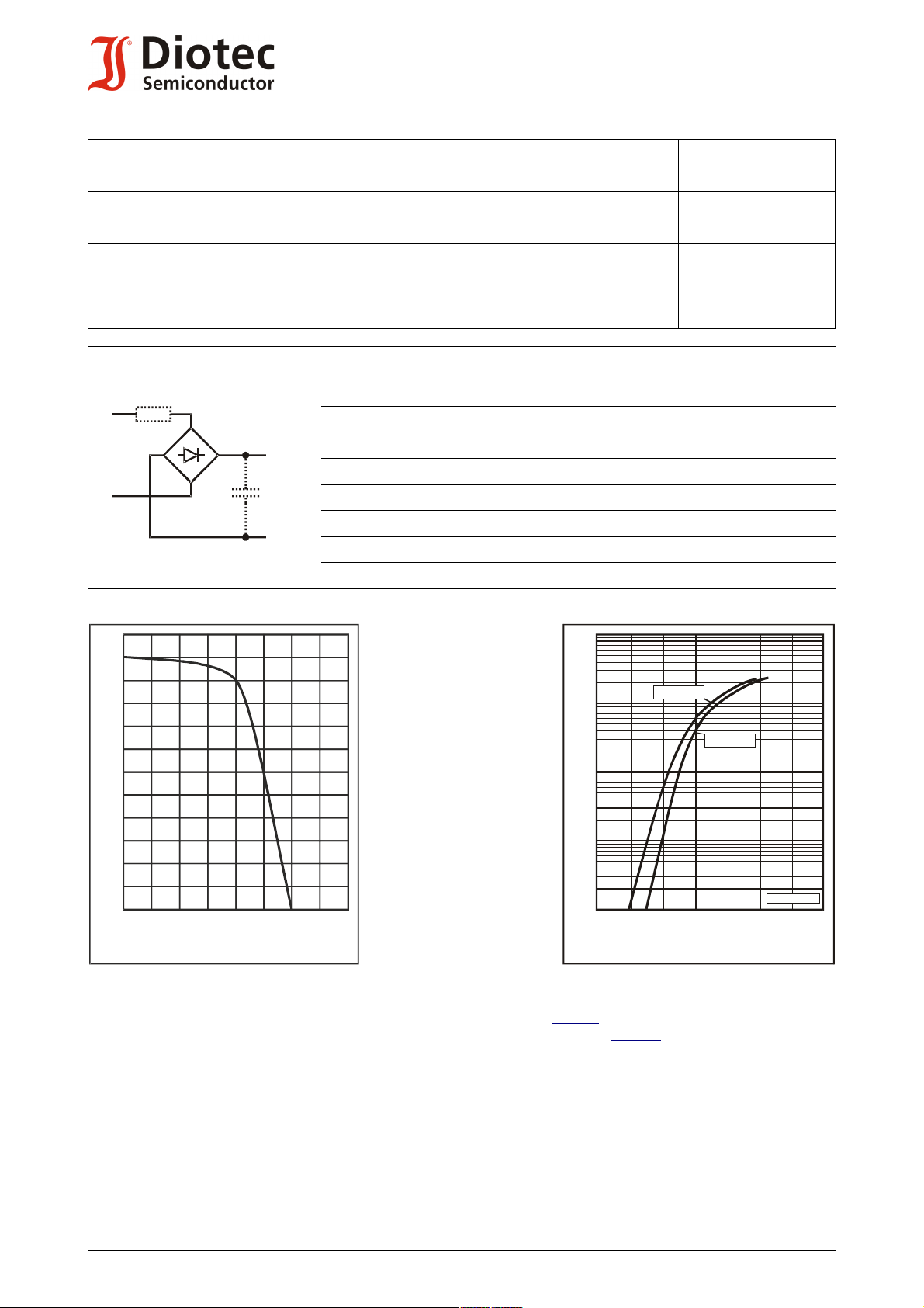
Forward characteristics (typical values)
Durchlasskennlinien (typische Werte)
0.4
VF0.8
1.0
1.2
1.4
[V] 1.8
T = 25°C
j
T = 125°C
j
270a-(12a-1v)
R
t
3)
C
L
4)
~
~
+
_
Rated forward current vs. temp. of the case
Zul. Richtstrom in Abh. v. d. Gehäusetemperatur
120
100
80
60
40
20
0
I
FAV
[%]
[°C]
T
C
150100
50
0
Characteristics Kennwerte
Forward voltage – Durchlass-Spannung Tj = 25°C IF = 8 A V
Leakage current – Sperrstrom Tj = 25°C VR = V
RRM
Reverse recovery time – Sperrverzug IF = 0.5 A through/über IR = 1 A to IR = 0.25 A t
Typical junction capacitance – Typische Sperrschichtkapazität VR = 4 V C
Typical thermal resistance junction to ambient (per device)
Typischer Wärmewiderstand Sperrschicht – Umgebung (pro Bauteil)
Typical thermal resistance junction to case (per device)
Typischer Wärmewiderstand Sperrschicht – Gehäuse (pro Bauteil)
R
R
F
I
R
rr
j
thA
thC
< 1.0 V 1)
< 5 µA 1)
typ. 1500 ns 1)
80 pF 1)
19 K/W 2)
3.0 K/W
Type
Typ
Recomm. protective resistance
Empf. Schutzwiderstand
Rt [Ω] 3)
Admiss. load capacitor at R
Zul. Ladekondensator mit R
CL [µF] 4)
GBU8A 0.2 20000
GBU8B 0.4 10000
GBU8D 0.8 5000
GBU8G 1.6 2500
GBU8J 2.4 1500
GBU8K 3.2 1000
GBU8M 4.0 800
t
t
1 Valid per diode – Gültig pro Diode
2 Valid, if leads are kept at ambient temperature at a distance of 5 mm from case
Gültig, wenn die Anschlussdrähte in 5 mm Abstand vom Gehäuse auf Umgebungstemperatur gehalten werden
3 Rt = V
4 CL = 5 ms / Rt If the Rt CL time constant is less than a quarter of the 50Hz mains period, CL can be charged completely in a
2 http://www.diotec.com/ © Diotec Semiconductor AG
/ I
Rt is the equivalent resistance of any protective element which ensures that I
RRM
FSM
Rt ist der Ersatzwiderstand eines jeglichen Schutzelementes, welches ein Überschreiten von I
single half wave of the mains. Hence, I
Falls die Rt CL Zeitkonstante kleiner ist als ¼ der 50Hz-Netzperiode, kann CL innerhalb einer einzigen
Netzhalbwelle komplett geladen werden. I
Disclaimer: See data book page 2 or website
Haftungssauschluss: Siehe Datenbuch Seite 2 oder oder Internet
FSM
occurs as a single pulse only!
FSM
tritt dann nur als Einzelpuls auf!
FSM
is not exceeded
FSM
verhindert
 Loading...