

Diotec DB25-16, DB25-14, DB25-12, DB25-10, DB25-08 Datasheet
...
Diotec
DB 25-005 … DB 25-16
3-Phase Si-Bridge Rectifiers Dreiphasen-Si-Brückengleichrichter
Nominal current 25 A
Nennstrom
Repetitive peak reverse voltage 50…1600 V
Periodische Spitzensperrspannung
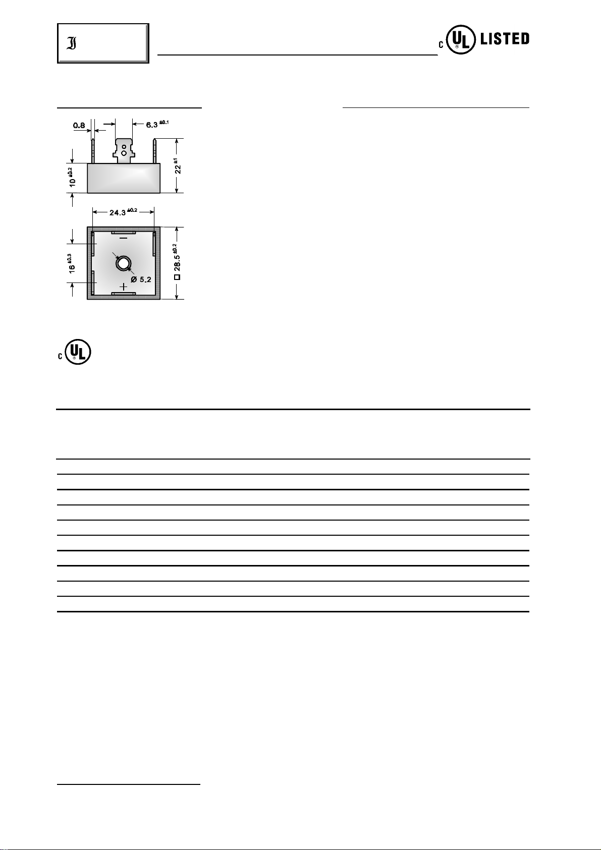
Plastic case with Al-bottom 28.5 x 28.5 x 10 [mm]
Kunststoffgehäuse mit Alu-Boden
Weight approx. 21 g
Gewicht ca.
Standard packaging: bulk
Dimensions / Maße in mm Standard Lieferform: lose im Karton
Listed by Underwriters Lab. Inc.® to U.S. and Canadian safety standards. File E175067
Von Underwriters Laboratories Inc.® unter Nr. E175067 registriert.
Maximum ratings Grenzwerte
Type Rep. peak reverse voltage ) Surge peak reverse voltage )
Typ Period. Spitzensperrspannung. ) Stoßspitzensperrspannung. )
V [V] V [V]
RRM RSM
1 1
1 1
DB 25-005 50 75
DB 25-01 100 150
DB 25-02 200 275
DB 25-04 400 500
DB 25-06 600 700
DB 25-08 800 900
DB 25-10 1000 1100
DB 25-12 1200 1300
DB 25-14 1400 1500
DB 25-16 1600 1700
Repetitive peak forward current f > 15 Hz I 100 A )
FRM
Periodischer Spitzenstrom
Rating for fusing, t <10 ms T = 25°C i t 600 A s
A
2 2
Grenzlastintegral, t <10 ms
Peak fwd. surge current, 50 Hz half sine-wave T = 25°C I 350 A
A FSM
Stoßstrom für eine 50 Hz Sinus-Halbwelle
1
) Valid for one branch – Gültig für einen Brückenzweig
2
) Valid, if the temperature of the case is kept to 120°C – Gültig, wenn die Gehäusetemperatur auf 120°C gehalten wird
314
01.01.99
2
DB 25-005 … DB 25-16
Diotec
Operating junction temperature – Sperrschichttemperatur T – 50…+150°C
Storage temperature – Lagerungstemperatur T – 50…+150°C
j
S
Characteristics Kennwerte
Max. current with cooling fin 300 cm T = 50°C R-load I 25.0 A
Dauergrenzstrom mit Kühlblech 300 cm C-load I 25.0 A
Forward voltage – Durchlaßspannung T = 25°C I = 12.5 A V < 1.05 V )
Leakage current – Sperrstrom T = 25°C V = V I < 10 µA
Isolation voltage terminals to case V >2500 V
2
A FAV
2
j F F
j R RRM R
FAV
ISO
Isolationsspannung Anschlüsse zum Gehäuse
Thermal resistance junction to case R < 2.4 K/W
thC
Wärmewiderstand Sperrschicht – Gehäuse
Admissible torque for mounting 10-32 UNF 18 ± 10% lb.in.
Zulässiges Anzugsdrehmoment M 5 2 ± 10% Nm
1
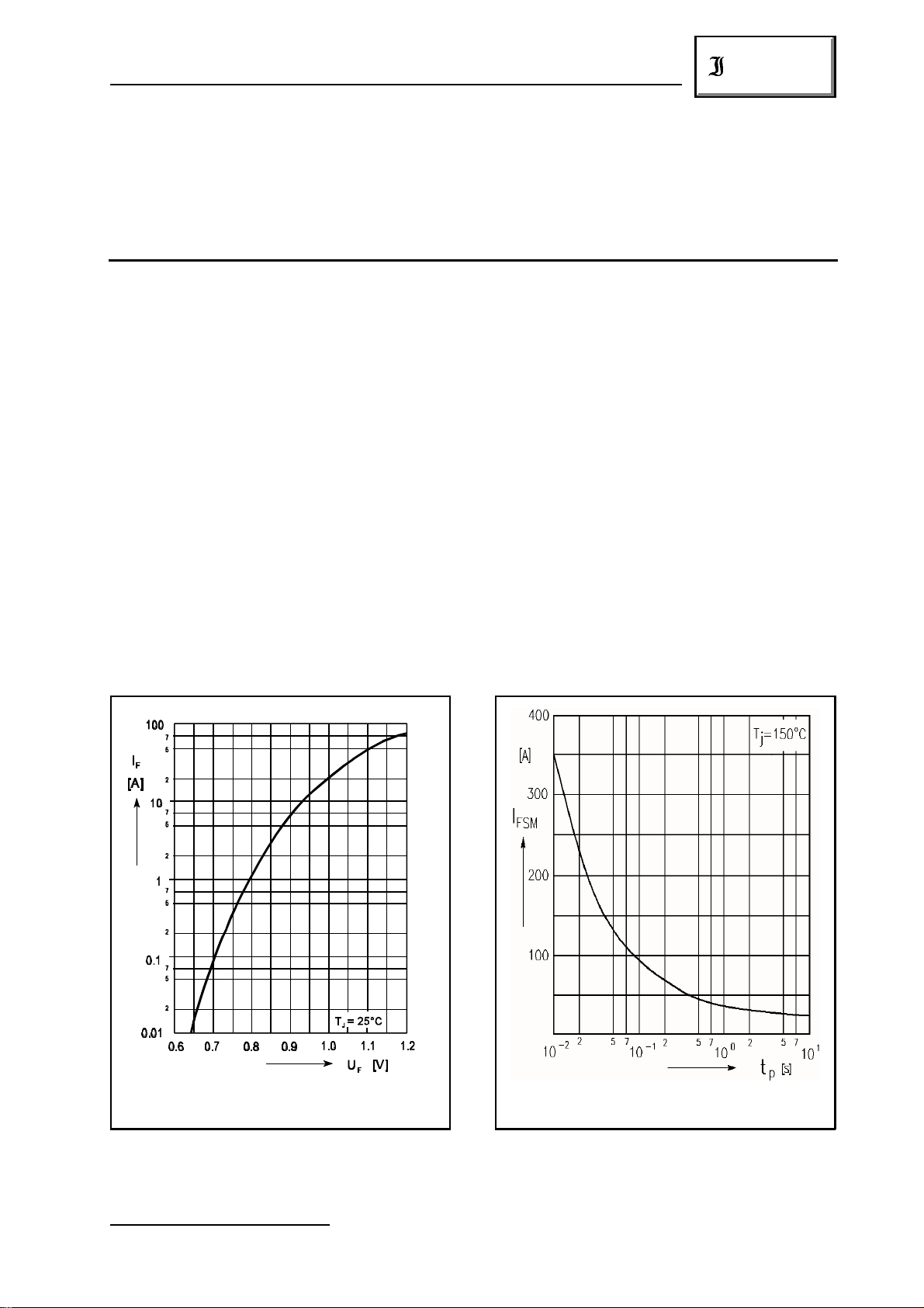
Forward characteristic (typical values) )
Durchlaßkennlinie (typische Werte) )
1
) Valid for one branch – Gültig für einen Brückenzweig
01.01.99
1
1
Max. surge current versus pulse duration
Max. Stoßstrom in Abh. von der Pulsdauer
315
 Loading...