

BAS40, BAS40-04, BAS40-05, BAS40-06
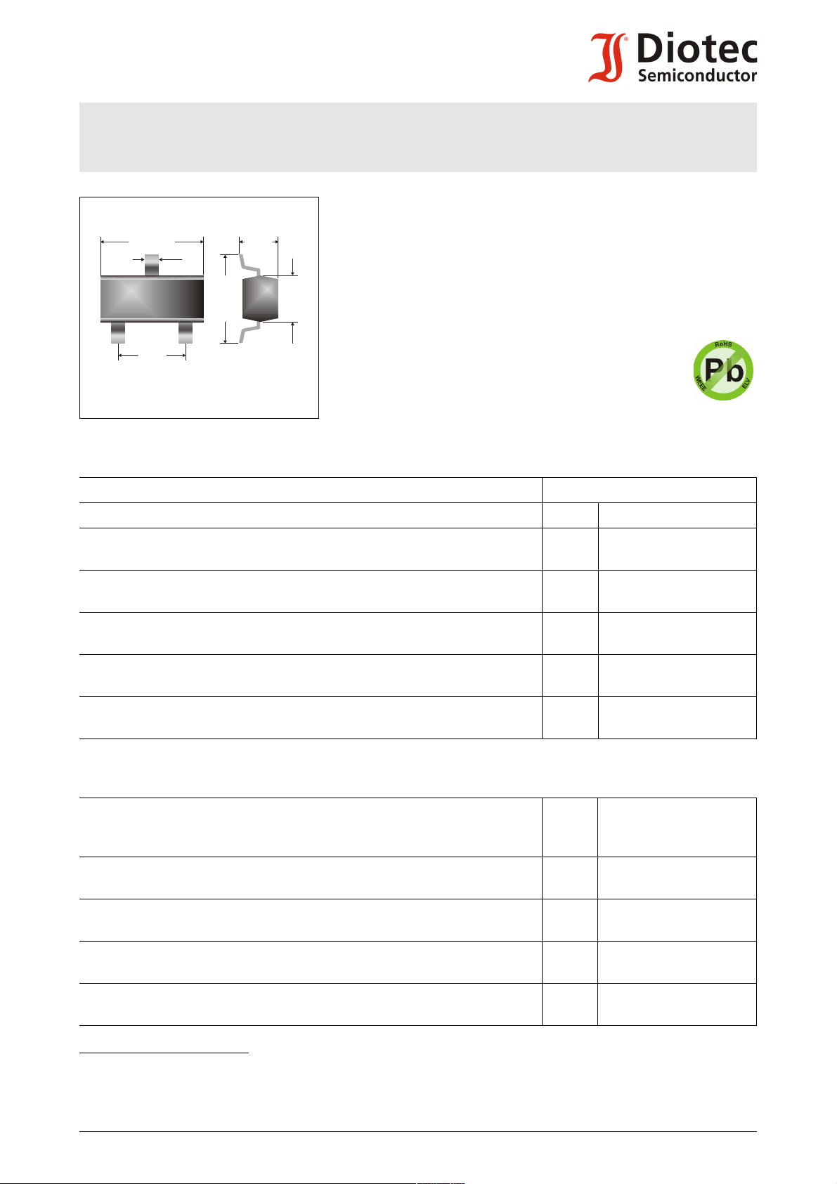
2.4
1.3
±0.1
1.1
+0.1
0.4
+0.1
2.9
±0.1
1
2
3
Type
Code
1.9
±0.1
-0.05
-0.2
±0.2
BAS40, BAS40-04, BAS40-05, BAS40-06
Surface Mount Schottky Barrier Single/Double Diodes
Schottky-Barrier Einzel-/Doppel-Dioden für die Oberflächenmontage
Version 2015-05-12
Power dissipation – Verlustleistung 310 mW
Repetitive peak reverse voltage
40 V
Periodische Spitzensperrspannung
Plastic case
Kunststoffgehäuse
SOT-23
(TO-236)
Weight approx. – Gewicht ca. 0.01 g
Plastic material has UL classification 94V-0
Gehäusematerial UL94V-0 klassifiziert
Standard packaging taped and reeled
Dimensions - Maße [mm]
Standard Lieferform gegurtet auf Rolle
Maximum ratings (TA = 25°C) Grenzwerte (TA = 25°C)
per diode / pro Diode BAS40-series
Power dissipation – Verlustleistung 1) P
Max. average forward current (dc)
tot
I
FAV
310 mW 2)
200 mA 2)
Dauergrenzstrom
Repetitive peak forward current
I
FRM
300 mA 2)
Periodischer Spitzenstrom
Non repetitive peak forward surge current
tp ≤ 1 s I
FSM
0.6 A
Stoßstrom-Grenzwert
Repetitive peak reverse voltage
V
RRM
40 V
Periodische Spitzensperrspannung
Junction temperature – Sperrschichttemperatur
Storage temperature – Lagerungstemperatur
T
j
T
S
-55...+150°C
-55…+150°C
Characteristics (Tj = 25°C) Kennwerte (Tj = 25°C)
Forward voltage 3)
Durchlass-Spannung 3)
Leakage current
Sperrstrom
Max. junction capacitance – Max. Sperrschichtkapazität
IF = 1 mA
IF = 10 mA
IF = 40 mA
VR = 30 V
VR = 40 V
V
F
V
F
V
F
I
R
I
R
C
T
< 380 mV
< 500 mV
< 1.00 V
< 200 nA
< 10 µA
5 pF
VR = 0 V, f = 1 MHz
Reverse recovery time – Sperrverzug
t
rr
< 5 ns
IF = 10 mA über/through IR = 10 mA bis/to IR = 1 mA
Thermal resistance junction to ambient air
R
thA
< 400 K/W 2)
Wärmewiderstand Sperrschicht – umgebende Luft
1 Total power dissipation of both diodes − Summe der Verlustleistungen beider Dioden
2 Mounted on P.C. board with 3 mm2 copper pad at each terminal
Montage auf Leiterplatte mit 3 mm2 Kupferbelag (Lötpad) an jedem Anschluss
3 Tested with pulses tp = 300 µs, duty cycle ≤ 2% – Gemessen mit Impulsen tp = 300 µs, Schaltverhältnis ≤ 2%
© Diotec Semiconductor AG http://www.diotec.com/ 1
BAS40, BAS40-04, BAS40-05, BAS40-06
21
323
1
21
3213
[%]
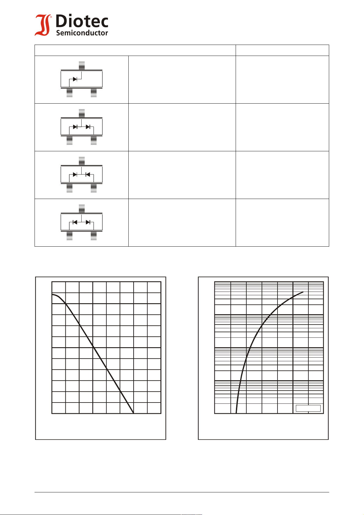
P
tot
Power dissipation versus ambient temperature )
Verlustleistung in Abh. von der Umgebungstemp. )
1
1
120
100
80
20
0
0 150
50 100
T
A
[°C]
60
40
Forward characteristics (typical values)
Durchlasskennlinien (typische Werte)
V
F
[V] 1.41.00.80.60.40
[A]
I
F
10
-4
10
-3
10
-2
10
-1
1
T = 25°C
j
Pinning – Anschlussbelegung Marking – Stempelung
Single Diode
Einzeldiode
BAS40 = 43
1 = A 2 = n.c./frei 3 = C
Dual diode, series connection
Doppeldiode, Reihenschaltung
BAS40-04 = 44
1 = A1 2 = C2 3 = C1/A2
Dual diode, common cathode
Doppeldiode, gemeinsame Katode
BAS40-05 = 45
1 = A1 2 = A2 3 = C1/C2
Dual diode, common anode
Doppeldiode, gemeinsame Anode
BAS40-06 = 46
1 = C1 2 = C2 3 = A1/A2
2 http://www.diotec.com/ © Diotec Semiconductor AG
 Loading...