

Diotec B500C7000-4000, B80C7000-4000, B40C7000-4000, B380C7000-4000, B250C7000-4000 Datasheet
...
Diotec
B…C 7000-4000
Silicon-Bridge Rectifiers Silizium-Brückengleichrichter
Nominal current – Nennstrom 7.0 A / 4.0 A
5.6
±0.2
32
±0.2
Alternating input voltage 40…500 V
Eingangswechselspannung
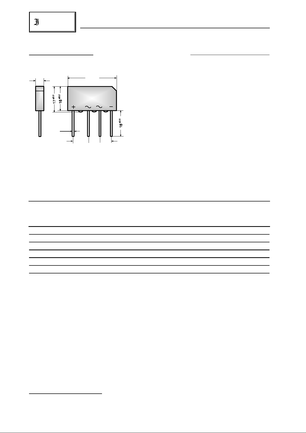
Plastic case 32 x 5.6 x 17 [mm]
Kunststoffgehäuse
Ø 1.2
10 7.5 7.5
Weight approx. – Gewicht ca. 9 g
Plastic material has UL classification 94V-0
Gehäusematerial UL94V-0 klassifiziert
Dimensions / Maße in mm Mounting clamp BO 2 see page 26
Befestigungsschelle BO 2 siehe Seite 26
Maximum ratings Grenzwerte
Type Alternating input volt. Rep. peak reverse volt. ) Surge peak reverse volt. )
Typ Eingangswechselspg. Period. Spitzensperrspg. ) Stoßspitzensperrspanng. )
V [V] V [V] V [V]
VRMS RRM RSM
1 1
1 1
B40C 7000-4000 40 80 100
B80C 7000-4000 80 160 200
B125C 7000-4000 125 250 400
B250C 7000-4000 250 500 800
B380C 7000-4000 380 800 1000
B500C 7000-4000 500 1000 1200
Repetitive peak forward current f > 15 Hz I 50 A )
FRM
Periodischer Spitzenstrom
Rating for fusing, t < 10 ms T = 25°C i t 310 A s
A
2 2
Grenzlastintegral, t < 10 ms
Peak fwd. surge current, 50 Hz half sine-wave T = 25°C I 250 A
A FSM
Stoßstrom für eine 50 Hz Sinus-Halbwelle
Operating junction temperature – Sperrschichttemperatur T – 50...+150°C
Storage temperature – Lagerungstemperatur T – 50...+150°C
1
) Valid for one branch – Gültig für einen Brückenzweig
2
) Valid, if leads are kept at ambient temperature at a distance of 10 mm from case
Gültig, wenn die Anschlußdrähte in 10 mm Abstand von Gehäuse auf Umgebungstemperatur gehalten werden
274
j
S
01.01.99
2
B…C 7000-4000
Diotec
Characteristics Kennwerte
Max. fwd. current without cooling fin T = 50°C R-load I 4.8 A )
Dauergrenzstrom ohne Kühlblech C-load I 4.0 A )
Max. current with cooling fin 300 cm T = 50°C R-load I 8.0 A
2
Dauergrenzstrom mit Kühlblech 300 cm C-load I 7.0 A
Leakage current – Sperrstrom T = 25°C V = V I < 10 µA
Thermal resistance junction to ambient air R < 15 K/W )
A FAV
A FAV
2
j R RRM R
FAV
FAV
thA
Wärmewiderstand Sperrschicht – umgebende Luft
Type Max. admissible load capacitor Min. required protective resistor
Typ Max. zulässiger Ladekondensator Min. erforderl. Schutzwiderstand
C [µF] R [ ]
L t
B40C 7000-4000 10000 0.5
B80C 7000-4000 5000 1.0
B125C 7000-4000 2500 2.0
B250C 7000-4000 1500 4.0
B380C 7000-4000 1000 5.0
B500C 7000-4000 800 6,5
1
1
1
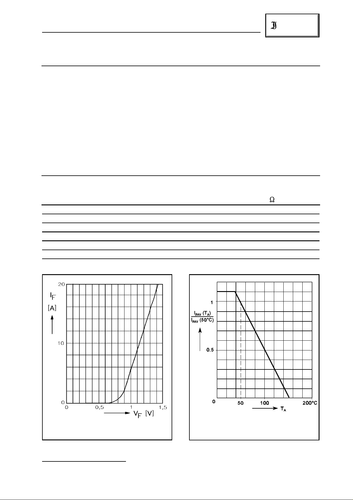
Rated forward current vs. ambient temperature
Typical forward characteristic for one branch
Durchlaßkennlinie für einen Brückenzweig
1
) Valid, if leads are kept at ambient temperature at a distance of 10 mm from case
Gültig, wenn die Anschlußdrähte in 10 mm Abstand von Gehäuse auf Umgebungstemperatur gehalten werden
01.01.99
Zulässiger Richtstrom in Abhängigkeit
von der Umgebungstemperatur
275
 Loading...