

Dionex UltiMate FLM-3100, UltiMate FLM-3300, UltiMate FLM-3200, UltiMate FLM-3100B, UltiMate FLM-3300B Operating Instructions Manual
...Page 1
UltiMate 3000 Series
Flow Managers and
Thermostatted Column Compartments
Operating Instructions
Revision: 1.1
Date: September 2007
© 2007 Dionex
Page 2

UltiMate 3000 Series: Flow Managers and Column Thermostats
Operating Instructions
Page 3

Declaration of Conformity
Product: Flow Manager and Column Compartment
Types: FLM-3100, FLM-3200, FLM-3300
FLM-3100B, FLM-3200B, FLM-3300B
Dionex Softron GmbH herewith declares conformity of the above products
with the respective requirements of the following regulations:
• Low-Voltage Equipment Directive 73/23/EEC
changed by 93/68/EEC
• EMC Directive 2004/108/EG
The electrical safety of the products was evaluated based on the following
standard:
• EN 61010-1: 2002
Safety requirements for electrical equipment for measurement, control
and laboratory use
Part 1: General Requirements
The Electromagnetic Compatibility (EMC) of the products was evaluated
based on the following standard:
• DIN EN 61326: 2004
Electrical equipment for measurement, control and laboratory use
EMC Requirements
This declaration is issued for the manufacturer
Dionex Softron GmbH
Dornierstrasse 4
D-82110 Germering
by the President, Dr. Peter Jochum.
August 1, 2007 _________________________
Dr. Peter Jochum
Operating Instructions Page I
Page 4
UltiMate 3000 Series: Flow Managers and Column Thermostats
Page II Operating Instructions
Page 5

UltiMate 3000 Series: Flow Managers and Column Thermostats
Table of Contents
1 Introduction................................................................................................................... 1
1.1 How to Use This Manual.......................................................................................1
1.2 Safety Information .................................................................................................1
1.2.1 Symbols on the Instrument and in the Manual .................................................. 2
1.2.2 General Safety Precautions................................................................................ 3
1.2.3 Consignes Générales de Sécurité....................................................................... 5
1.3 Intended Use .......................................................................................................... 8
1.4 Federal Communications Commission (FCC) Note.............................................. 8
2 Overview ........................................................................................................................9
2.1 Product Overview .................................................................................................. 9
2.2 Theory of Operation (UltiFlow) ..........................................................................11
2.3 Supported Configurations.................................................................................... 12
2.3.1 General............................................................................................................. 12
2.3.2 Biocompatible Flow Managers........................................................................ 13
2.4 General Flow Manager Design............................................................................ 17
2.5 Column Switching Valve..................................................................................... 18
2.6 Flow Splitter ........................................................................................................ 19
2.7 Front Panel Display and Controls........................................................................ 20
2.8 Rear Panel Connectors......................................................................................... 21
2.9 Leak Sensors........................................................................................................22
2.10 System Wellness..................................................................................................23
3 Installation................................................................................................................... 25
3.1 Facility Requirements.......................................................................................... 25
3.2 Unpacking............................................................................................................ 25
3.3 Positioning the Flow Manager in the UltiMate 3000 System.............................. 26
3.4 Connecting the Flow Manager............................................................................. 27
3.4.1 USB.................................................................................................................. 27
3.4.2 Power Connection............................................................................................ 27
3.4.3 Digital I/O........................................................................................................ 28
3.5 Opening the Front Panel Door............................................................................. 28
3.6 Preparing the Flow Manager ............................................................................... 29
3.6.1 Installing a Separation Column .......................................................................31
3.6.2 Connecting the Capillaries to the Column Switching Valve...........................35
3.6.3 Installing a Trap Column.................................................................................36
3.6.4 Connecting the Flow Splitter...........................................................................37
3.7 Manual Injection Port .......................................................................................... 39
Operating Instructions Page i
Page 6

UltiMate 3000 Series: Flow Managers and Column Thermostats
4 User Interface ..............................................................................................................41
4.1 Power-Up.............................................................................................................41
4.2 Status Screen........................................................................................................ 41
4.3 Soft Key Menus ................................................................................................... 42
4.4 Menu Structure and Layout ................................................................................. 43
4.4.1 Main Menu....................................................................................................... 45
4.4.2 Control Menu................................................................................................... 46
4.4.3 Information Menu............................................................................................ 47
4.4.4 Configuration Menu......................................................................................... 48
5 Software Control by Chromeleon ............................................................................. 49
5.1 General................................................................................................................. 49
5.2 Installing the Flow Manager in Chromeleon.......................................................49
5.3 Assigning the Flow Splitter ................................................................................. 56
5.4 Operating the Flow Manager with Chromeleon .................................................. 57
5.5 Column Identification System (Column ID) .......................................................58
5.6 Splitter Identification System (Splitter ID).......................................................... 59
5.7 Diagnostics........................................................................................................... 60
6 Troubleshooting ..........................................................................................................61
6.1 Overview.............................................................................................................. 61
6.2 Error Messages .................................................................................................... 62
6.3 Chromeleon Diagnostics Messages ..................................................................... 66
7 Routine Maintenance.................................................................................................. 69
7.1 General Notes ...................................................................................................... 69
7.2 Maintenance Intervals.......................................................................................... 71
7.3 Flow Control Valve .............................................................................................72
7.4 Replacing the Fuses ............................................................................................. 73
7.5 Drying the Fluid Leak Sensor.............................................................................. 74
7.6 Exchanging the Splitter Cartridge) ...................................................................... 76
7.7 Column Switching Valve..................................................................................... 79
7.8 Shutting Down the Flow Manager....................................................................... 81
8 Technical Information................................................................................................ 83
9 Accessories, Consumables and Spare Parts ............................................................. 85
9.1 Standard Accessories (included in the shipment)................................................ 85
9.2 Consumables, Spare Parts, and Optional Accessories......................................... 86
10 Technical Appendix - Pin Assignment...................................................................... 91
11 Index............................................................................................................................. 93
Page ii Operating Instructions
Page 7

UltiMate 3000 Series: Flow Managers and Column Thermostats
1 Introduction
1.1 How to Use This Manual
The layout of this manual is designed to provide quick reference to the sections of interest
to the user. However, in order to obtain a full understanding the flow manager and
thermostatted column compartment, Dionex recommends that you review the manual
thoroughly before beginning operation of the module.
Almost all descriptions in the manual apply to all flow managers of the UltiMate 3000 system
and cover both the standard (stainless steel) and biocompatible models. Therefore, the terms
"the flow manager" and/or "the FLM" are used throughout the manual. If some detail applies
to only one model or version, the model (or version) is identified by name.
Note: The device configuration may vary (e.g., one or two column switching valves);
therefore, not all descriptions necessarily apply to your particular instrument.
The descriptions in this manual refer to firmware version 2.30 and Chromeleon
version 6.80 Service Pack 2.
The information contained in this manual is subject to change without notice and should
not be construed as a commitment by Dionex. Dionex assumes no responsibility for any
errors that may appear in this document. This document is believed to be complete and
accurate at the time of publication. In no event shall Dionex be liable for incidental or
consequential damages in connection with or arising from the use of this document.
CHROMELEON® is a registered trademark of Dionex. UltiMate™ is a trademark of Dionex.
All other trade or company names mentioned are subject to the copyright and the property and
trademark rights of the respective companies.
All rights reserved, including those for photomechanical reproduction and storage on
electronic media. No part of this publication may be copied or distributed, transmitted,
transcribed, stored in a retrieval system, or transmitted into any human or computer language,
in any form or by any means, electronic, mechanical, magnetic, manual, or otherwise, or
disclosed to third parties without the express written permission of Dionex.
1.2 Safety Information
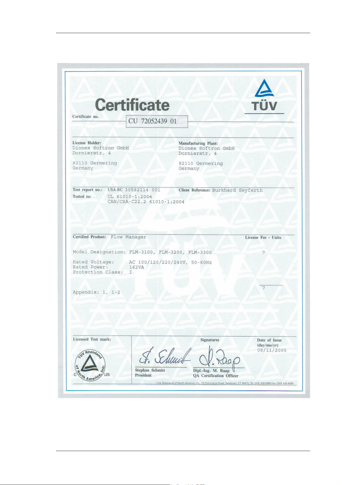
The CE Mark label and cTUVus Mark safety label on the instrument indicate that the
instrument is in compliance with the related standards (→ pages I and II).
Operating Instructions Page 1
Page 8

UltiMate 3000 Series: Flow Managers and Column Thermostats
1.2.1 Symbols on the Instrument and in the Manual
The table below shows the symbols used on the instrument:
Symbol Description
Alternating current—Courant alternatif
˜
Power supply is on (−) — L'instrument est mis sous tension (−) and
Power supply is off (O)— L'instrument est mis hors tension (O)
Surface becomes hot during operation—La surface devient chaude lors du
fonctionnement.
Refer to the operating instructions to prevent risk of harm to the operator and to
protect the instrument against damage.
Référez-vous au ce manuel pour éviter un risque de blessure à l'opérateur et/ou de
protéger l'instrument contre des dommages.
Label according to the "Measures for Administration of the Pollution Control of
Electronic Information Products" (China RoHS) guideline
Étiquette "Measures for Administration of the Pollution Control of Electronic
Information Products" (China RoHS)
WEEE (Waste Electrical and Electronic Equipment) label—For more information,
refer to the WEEE Information section in the manual binder.
Étiquette de WEEE (Waste Electrical and Electronic Equipment) —Pour plus
d'information, référez-vous à la section WEEE Information dans ce fichier.
At various points throughout the manual, messages of particular importance are indicated by
certain symbols:
Tip: Indicates general information, as well as information intended to
optimize the performance of the instrument.
Important: Indicates that failure to take note of the accompanying information
could cause wrong results or may result in damage to the instrument.
Important: Indique que ne pas tenir compte de l'information jointe peut conduire
à de faux résultat ou endommager l'instrument.
Warning: Indicates that failure to take note of the accompanying information
may result in personal injury.
Avertissement: Indique que ne pas tenir compte de l'information jointe peut
entraîner des blessures corporelles.
Page 2 Operating Instructions
Page 9

UltiMate 3000 Series: Flow Managers and Column Thermostats
1.2.2 General Safety Precautions
When working with analytical instrumentation, you should know the potential hazards of
using chemical solvents.
Tips: Before initial operation of the flow manager, make sure that you are familiar
with the contents of this manual.
Observe any warning labels on the device and refer to the related sections in
these operating instructions.
For the general safety precautions in French, refer to Consignes Générales
de Sécurité (→ page 5).
Please observe the following general safety precautions when operating the instrument or
carrying out any maintenance work:
• Install the HPLC system in a well-ventilated laboratory. If the mobile phase includes
volatile or flammable solvents, do not allow them to enter the workspace.
• For minimum interference effects, all components of the analytical system should be
connected to the same mains output (same phase).
• The flow manager is primed with a mixture of isopropanol and water (20:80). During
initial operation of the flow manager, make sure that the used solvents used are miscible.
Otherwise, follow the appropriate intermediate steps.
• To prevent damage to the flow manager when lifting or moving, always lift the unit by the
bottom sides or sides. Lifting the flow manager by the bottom front or by the front panel
door may damage the door.
• The front panel tilts downward. Do not place any heavy objects on the open front panel
door. This may damage the door.
• Do not touch any metal parts inside the column chamber while the temperature set point is
> 50 °C (122 °F). Wait for the chamber to cool down, for example, before changing a
column or before performing any maintenance procedures.
• When operating the HPLC system, always set a lower pressure limit for the system pump.
This prevents damage resulting from leakage or from running the pump dry.
• When connecting the capillaries, make sure that the connectors are free from
contaminants. Even minute particles may cause damage to the flow splitter, flow control
valve, and column.
Operating Instructions Page 3
Page 10

UltiMate 3000 Series: Flow Managers and Column Thermostats
• Use only standard HPLC solvents (HPLC-grade: 0.2 µm filtered) and buffers that are
compatible with components in the flow path of the flow manager. Note the special
properties of the solvents such as viscosity, boiling point, UV absorption (UV/VIS
detector), and refractive index (refractive index detector).
Buffer concentration: typically up to 1 mol/L (0.1 mol/L if chloride ions are present).
• After operation, rinse out buffers and solutions that form peroxides from your HPLC
system.
• Before switching from buffer to organic solution, rinse the analytical system thoroughly
with deionized or HPLG-grade water.
• When switching to another solvent, ensure that the new solvent is miscible with the one
contained in the pump. Otherwise, the analytical system can be damaged; for example, by
flocculation.
• Avoid open flames and sparks, in particular if the mobile phase includes volatile or
flammable solvents.
• If a leak occurs, turn off the flow manager immediately, stop the pump flow, and remedy
the situation.
• When the front, side or rear panels are removed, dangerous electrical connections will be
exposed. Disconnect the flow manager from all power sources before removing the panels.
Remove panels only when instructed to do so in these instructions.
• Always replace blown fuses with the original spare fuses from Dionex (→ Replacing the
Fuses, page 73).
• Replace faulty power cords and communication cables.
• Many organic solvents and buffers are toxic. Know the toxicological properties of all
mobile phases that you are using.
• If the toxicological properties of a sample are unknown to you, treat it as if it contains a
potentially harmful substance.
• Wear goggles when handling mobile phases or operating the instrument. An eye wash
facility and a sink should be close to the unit. If any mobile phase splashes on the eyes or
skin, wash the affected areas with sufficient water and seek medical attention.
• Dispose of all waste mobile phase in an environmentally safe manner that is consistent
with all local regulations. Do not allow flammable and/or toxic solvents to accumulate.
Follow a regulated, approved waste disposal program. Never dispose of flammable and/or
toxic solvents through the municipal sewage system
Page 4 Operating Instructions
Page 11

UltiMate 3000 Series: Flow Managers and Column Thermostats
• In an UltiMate 3000 system, some tubing is made of PEEK. While this polymer has
superb chemical resistance to most organic solvents, it tends to swell when it is in contact
with trichlormethane (CHCl3), dimethyl sulfoxide (DMSO), or tetrahydrofuran (THF). In
addition, it is attacked by concentrated acids such as sulfuric acid and nitric acid (swelling
or attack by acid is not a problem with brief flushing procedures).
• Do not use PEEK tubing that is stressed, bent, or kinked.
• Wear goggles when handling fused silica tubing (e.g., during, installation and cutting).
• Before interrupting operation for several days or more, observe the precautions in Shutting
Down the Flow Manager (→ page 81).
• Use original Dionex spare parts only. Substituting non-Dionex parts or using non-Dionex
accessories may impair the performance of the instrument.
• Do not use the module in ways other than those described in this manual.
1.2.3 Consignes Générales de Sécurité
Veuillez noter: Avant de commencer à utiliser l'instrument, assurez-vous que vous
vous êtes familiarisés avec le contenu de ce manuel.
Observez les étiquettes d'avertissement sur l'appareil et référez-vous
aux sections correspondantes dans ce mode d'emploi.
Veuillez observer les consignes générales de sécurité suivantes lorsque vous utilisez
l'instrument ou que vous procédez à des opérations de maintenance:
• Installez le système HPLC dans un laboratoire bien ventilé. Si la phase mobile contient des
solvants volatils ou inflammables, empêchez qu'ils ne pénètrent dans l'espace de travail.
• Afin d'éviter au maximum les interférences, tous les éléments du système analytique
doivent être raccordés à la même ligne secteur (même phase).
• L'instrument est stocké sous isopropanol et eau. Au cours démarrage de l'instrument,
assurez-vous que les solvants utilisés soient miscibles. Sinon, suivez les étapes
intermédiaires appropriées.
• Lorsque vous soulevez ou l’instrument, tenez-le toujours par le dessous ou par les côtés de
l'unité. Soulever l’instrument par la partie avant inférieure ou par le panneau avant peut
endommager la porte.
• Ne placez aucun objet lourd sur la porte ouverte du panneau avant. Ceci pourrait
endommager la porte.
Operating Instructions Page 5
Page 12

UltiMate 3000 Series: Flow Managers and Column Thermostats
• Ne touchez à aucune partie en métal à l'intérieur du compartiment de colonne tant que le
point de réglage de température est > 50 °C (122 °F). Attendez que le four refroidisse, par
exemple, avant de changer une colonne ou avant de procéder à tous travaux de
maintenance.
• Réglez toujours une limite de pression minimum pour le système HPLC. Ceci prévient les
dommages résultant de fuites ou du fonctionnement à sec de la pompe.
• Lorsque vous connectez les capillaires, assurez-vous que les raccords sont exempts de tout
contaminant. Même d'infimes particules peuvent causer des dommages au système (ex.
diviseur de débit, vanne de régulation de débit et colonne).
• Utilisez uniquement des solvants HPLC (qualité HPLC : filtrés à 0.2 µm) et des sels
compatibles avec les composants des circuits hydrauliques de l’instrument. Vérifiez les
propriétés spécifiques des solvants telles que la viscosité, le point d'ébullition, l'absorption
UV (détecteur UV/VIS) et l’indice de réfraction (réfractomètre).
Concentration en sels: généralement inférieure à 1 mol/L (0.1 mol/L si présence d’ions
chlorure).
• Après utilisation, purgez le système des tampons et des susceptibles de former des
peroxydes.
• Lorsque vous passez d’une solution saline à un solvant organique, effectuez un rinçage
intermédiaire du système HPLC à l'eau dé-ionisée ou qualité HPLC.
• Lorsque vous passez à un autre solvant, assurez-vous que le nouveau solvant soit miscible
avec celui qui se trouve dans le système HPLC. Dans le cas contraire, le système HPLC
peut être endommagé; par exemple, par des floculations!
• Evitez les flammes nues et les sources d’étincelles à proximité, en particulier si la phase
mobile contient des solvants volatils ou inflammables.
• Si une fuite se produit, arrêtez immédiatement l’instrument, stoppez le débit de la pompe
et remédiez au problème.
• Quand les capots de protection de l’appareil sont démontés, vous êtes exposés à des
connexions électriques sous haute tension. Débranchez l'instrument de toute source
d'alimentation électrique avant de retirer les capots. Ne démontez les capots de protection
que si cela est explicitement demandé au cours de ces instructions.
• Remplacez toujours les fusibles grillés par des fusibles de rechange d'origine Dionex
(→ Replacing the Fuses, page 73).
• Remplacez les cordons d'alimentation électrique et les câbles de communication
défectueux.
• De nombreux solvants organiques et solutions salines sont toxiques. Informez-vous des
propriétés toxicologiques de toutes les phases mobiles que vous utilisez.
• Les propriétés toxicologiques de nombreux échantillons peuvent être mal connues. Au
moindre doute concernant un échantillon, traitez-le comme s'il contenait une substance
potentiellement dangereuse.
Page 6 Operating Instructions
Page 13

UltiMate 3000 Series: Flow Managers and Column Thermostats
• Portez des lunettes de protection lorsque vous manipulez des phases mobiles ou que vous
utilisez l'instrument. Une installation permettant de se laver les yeux ainsi qu'un lavabo
doivent se trouver à proximité du système. Si une phase mobile, quelle qu'elle soit, entre
en contact avec vos yeux ou votre peau, rincez abondamment la zone affectée à l’eau, puis
consultez un médecin.
• Débarrassez-vous de tous les déchets de phase mobile de manière écologique,
conformément à la règlementation en vigueur au niveau local. Empêchez impérativement
l'accumulation de solvants inflammables et/ou toxiques. Suivez un programme
d'élimination des déchets règlementé et approuvé. Ne jetez jamais de solvants
inflammables et/ou toxiques dans le système municipal d'évacuation des eaux usées.
• Dans un système UltiMate 3000, certains tubes sont en PEEK. Bien que ce polymère
présente une excellente résistance chimique à la plupart des solvants organiques, il a
tendance à gonfler lorsqu'il est en contact prolongé avec du chloroforme (CHCl3), du
diméthyle sulfoxyde (DMSO) ou du tétrahydrofurane (THF). De plus, il est attaqué par
des acides concentrés tels que l'acide sulfurique et l'acide nitrique (ces acides peuvent
cependant être utilisés dans le cadre de procédures de nettoyage, à condition que
l’exposition soit brève).
• N'utilisez pas de tubes PEEK écrasés, pliés ou abîmés.
• Portez des lunettes de protection lorsque vous manipulez des capillaires en silice fondue
(par example pendant l'installation ou découper).
• Avant d'interrompre le fonctionnement pendant plusieurs jours ou plus, observez les
précautions figurant en Shutting Down the Flow Manager (→ page 81).
• Utilisez des pièces de rechange d'origine Dionex. Effectuer des remplacements par des
pièces ne provenant pas de Dionex ou utiliser des accessoires ne provenant pas de Dionex
peut affecter les performances de l'instrument.
• N'utilisez pas l'instrument de manière autre que celles décrites dans ce manuel.
Operating Instructions Page 7
Page 14

UltiMate 3000 Series: Flow Managers and Column Thermostats
1.3 Intended Use
The flow manager is designed to perform equally well as a dependable system for routine
analyses or as a sophisticated research instrument for use in nano, capillary, and micro
HPLC (high performance liquid chromatography) applications, especially as part of the
UltiMate 3000 system. However, it can also be used with other HPLC systems if adequate
control inputs and outputs are available. A PC with USB port is required.
The flow manager is controlled by the Chromeleon Chromatography Management System.
Being part of the UltiMate 3000 system, the detector can also be operated with other data
systems, such as Analyst® (Applied Biosystems/MDS Sciex), Compass™/ HyStar™ (Bruker
Daltonics), or Xcalibur™ (Thermo Scientific). To do so, installation of the DCMS
Chromatography Mass Spectrometry Link) software is required in addition to the installion of
the data system.
Please note that the flow manager may only be operated with the accessories originally
supplied with the instrument (→ page 85) and within its technical specifications (→ page 83).
Link
(Dionex
Use only standard solvents and water of at least HPLC grade (0.2 µm filtered), or better LCMS grade and buffers that are compatible with components in the flow path of the flow
manager. If water from water purification systems that are not properly maintained is used,
polymeric contamination may seriously damage the column and may rapidly block solvent
filters. Note the special properties of the solvents such as viscosity, boiling point, UV
absorption (UV/VIS detector), and refractive index (refractive index detector).
Buffer concentration: typically up to 1 mol/L (0.1 mol/L if chloride ions are present).
If there is a question regarding appropriate usage, contact Dionex before proceeding.
Dionex is not liable for any damage, material or otherwise, resulting from inappropriate or
improper use of the instrument.
1.4 Federal Communications Commission (FCC) Note
This equipment has been tested and found to comply with the limits for a Class A digital
device, pursuant to part 15 of the U.S. FCC Rules. These limits are designed to provide
reasonable protection against harmful interference when the equipment is operated in a
commercial environment. This equipment generates, uses, and can radiate radio frequency
energy and, if not installed and used in accordance with the instruction manual, may cause
harmful interference to radio communications. Operation of this equipment in a residential
area is likely to cause harmful interference, in which case the user will be required to
correct the interference at his expense.
Page 8 Operating Instructions
Page 15

UltiMate 3000 Series: Flow Managers and Column Thermostats
2 Overview
2.1 Product Overview
The flow manager is a reliable module of the UltiMate 3000 system and performs equally
well as a dependable system for routine analyses or as a sophisticated research instrument
for nano, capillary, and micro HPLC applications. The design has been optimized for
minimum dead volume and maximum efficiency.
• The flow splitter (→ Fig. 1, page 11) delivers the low flow rates required for nano,
capillary, and micro HPLC applications. The flow manager is fitted with a flow splitter
identification system that allows you to store splitter-specific information on a chip card
and read it out whenever you want.
• An electronic splitter identification module (→ Splitter Identification System (Splitter ID),
page 59) automatically adapts the system settings to the used splitter cartridge. The
module also allows you to store splitter-specific information (split ratio, flow control
settings) on a chip card and read it out whenever you want. In addition, the parameters
required for flow splitting are set automatically.
• UltiFlow™ technology with active control of the splitter flow keeps the set flow rates
constant, independent of outside influences. Thus, the flow rate is not influenced by the
solvent composition, solvent gradients, different viscosities, or analyses at different
temperatures. In the same way, effects from column ageing and partial clogging will be
compensated.
• Thermoelectric elements heat or actively cool the column chamber and all internal
components to the desired temperature. Heat exchangers allow fast temperature changes
and ensure independence from the ambient temperature, even if the temperature set point
is below the ambient temperature.
• The flow manager allows compartment cooling by max. 15K from the ambient
temperature. The lower temperature limit is +5 °C (+41 °F).
• The columns can be warmed up to max. +85 °C (+185 °F). An increase in temperature
from 20 °C to 50 °C (68 °F to 122 °F) is realized in less than 25 minutes. This corresponds
to an average performance of 2-4 K per minute.
• Temperature control allows keeping the column temperature constant. If the ambient
temperature changes during the analysis, the increased heating or cooling ensures that the
column temperature remains constant. The maximum deviation is ± 0.1 °C.
• Several columns of different length (maximum length: 30 cm) can be installed in the
column chamber. An electronic column identification module allows GLP-compliant
documentation of the column type and all important column parameters (→ Column
Identification System (Column ID), page 58).
Operating Instructions Page 9
Page 16

UltiMate 3000 Series: Flow Managers and Column Thermostats
• Depending on the configuration, the flow manager is equipped with one or two column
switching valves (→ Supported Configurations, page 12), e.g., for applications that require
different columns at frequent intervals at similar temperatures.
• The flow manager is fully controlled by the Chromeleon Chromatography Management
System, providing a high degree of system integration.
• All surfaces in the column chamber are made of materials that provide maximum
resistance to the most commonly used HPLC solvents.
• The flow managers of the UltiMate 3000 system are available as biocompatible versions,
also. For information about the characteristics of the biocompatible devices, refer to
section 2.3.2 (→ page 13).
Page 10 Operating Instructions
Page 17
UltiMate 3000 Series: Flow Managers and Column Thermostats
r
Valve
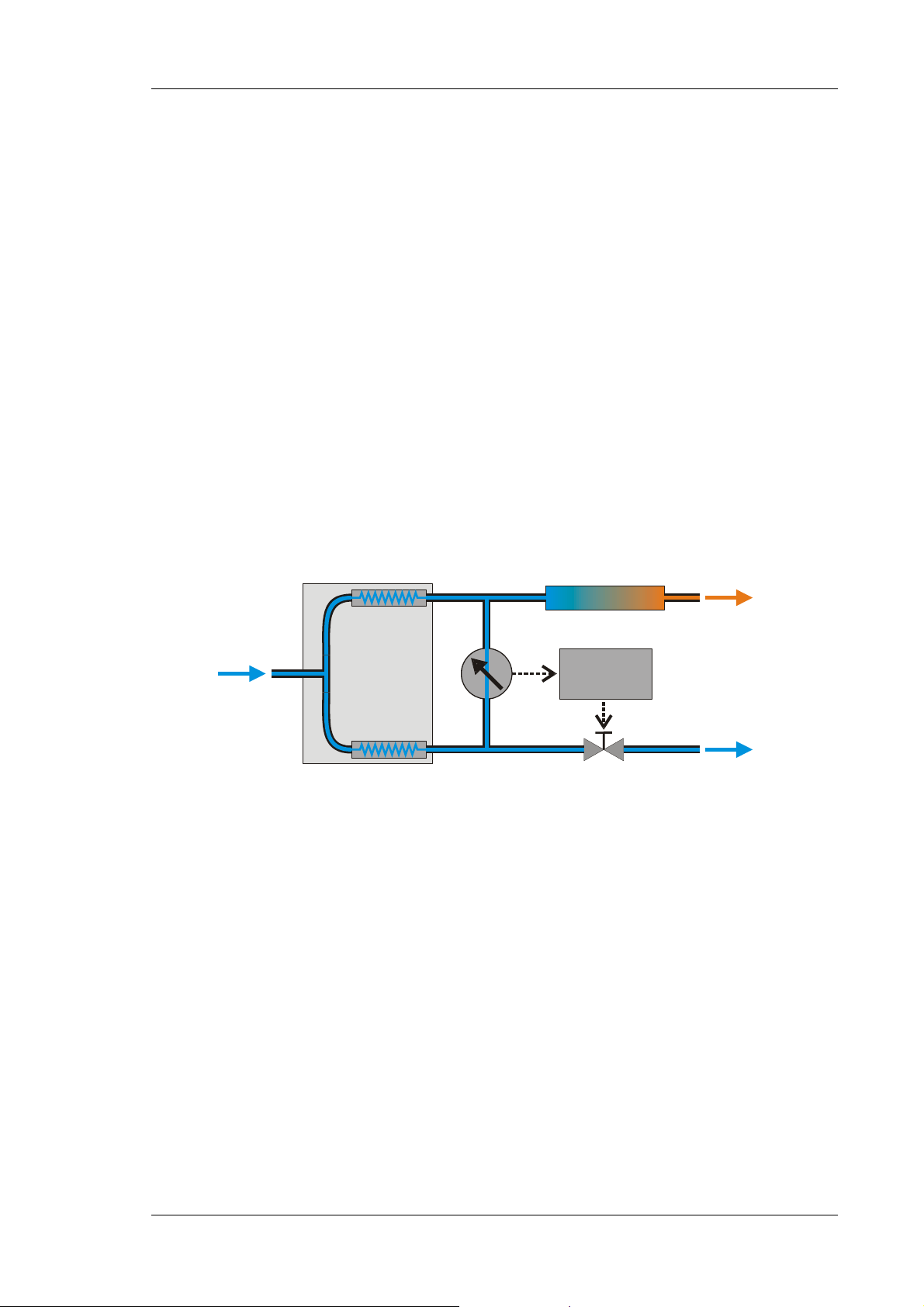
2.2 Theory of Operation (UltiFlow)
The fundamental requirement on a flow manager for liquid chromatography is the ability
to create constant low flow rates for nano, capillary, and micro HPLC applications, as well
as to equalize the temperature. The flow managers of the UltiMate 3000 system are fitted
with a flow splitter with integrated flow control that ensures constant flow rates, ranging
from micro liter to nano liter flows. The flow rate is influenced neither by varying column
backpressures nor by the temperature or solvent viscosity.
The flow splitter is equipped with two fluidic resistors that split the flow from the pump in
the reciprocal ratio of the resistance. To ensure identical pressure drop at both resistors, the
outputs of the flow splitter are connected via a cross arm with integrated flow meter. A
controller adjusts the unbalance flow to a very low offset value near zero to flush the cross
arm with fresh solvent permanently. To ensure this, the waste path includes an adjustable
valve that adjusts in dependence of the column pressure (→ Fig. 1).
This innovative method creates constant low flow rates based on the split ratio and the pump
flow. Different lowest flow rates are created by different pump flow rates, but they are always
split according to the split ratio. This is independent of the solvent composition and the
column pressure.
Column
Control
Detecto
Waste
Pump
Flow splitter
Flow meter
1:100
Fig. 1: Operation principle of flow splitting with control
For temperature equalization, temperature stability is more important than the absolute
precision of the setting. The flow manager contains advanced electronic circuits that can
maintain the selected temperature with a precision of ±0.1 °C.
The thermo-optimized design reduces the time required to equilibrate the temperature between
the column and the solvent. The Peltier elements of the flow manager heat up and cool down
the columns. The heat exchanger inside the column chamber also helps to bring the air and all
components in the chamber to the desired temperature, including the flow splitter and column
switching valve(s).
Operating Instructions Page 11
Page 18
UltiMate 3000 Series: Flow Managers and Column Thermostats
These procedures ensure that
• The temperature of the stationary phase remains constant over the total column length.
• The column and the solvent have the same temperature during the analysis.
In this way, analytical separation is performed at the nominal temperature, thus, minimizing
fronting and tailing as well as retention time variations.
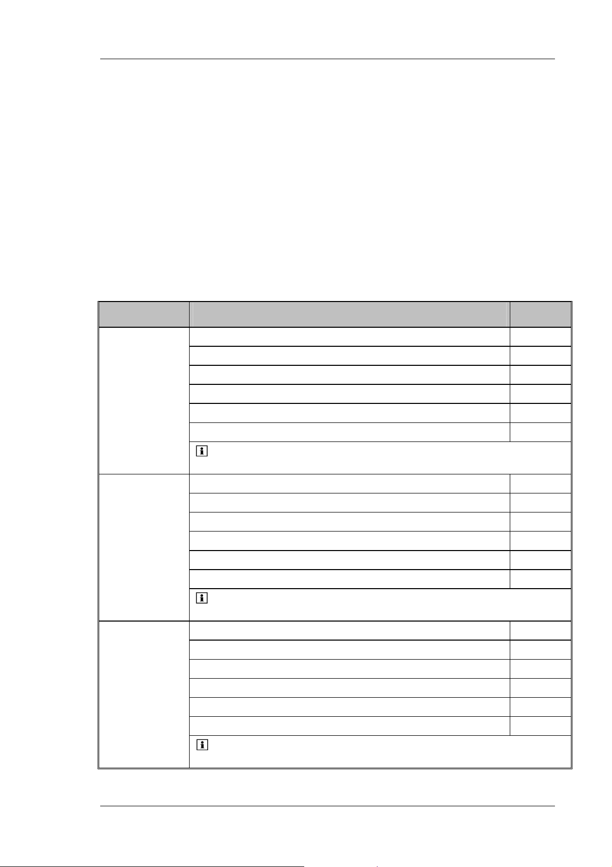
2.3 Supported Configurations
2.3.1 General
For an overview of the currently available models, refer to the list below. If you have any
questions, do not hesitate to contact your Dionex sales representative or distributor.
Application Description Part No.
FLM-3100 with two 10-port micro switching valves 5720.0010
Nano HPLC
Capillary
and/or
Monolithic
HPLC
Micro HPLC
FLM-3100B, same as FLM-3100, but biocompatible version 5721.0010
FLM-3200 with 10-port micro and 6-port nano switching valves (1 each) 5720.0020
FLM-3200B, same as FLM-3200, but biocompatible version 5721.0020
FLM-3300 with one 10-port micro switching valve 5720.0030
FLM-3300B, same as FLM-3300, but biocompatible version 5721.0030
Tip: These flow managers are fitted with a splitter cartridge
for a split ratio of 1:1000.
FLM-3100 with two 10-port micro switching valves 5720.0015
FLM-3100B, same as FLM-3100, but biocompatible version 5721.0015
FLM-3200 with 10-port micro and 6-port nano switching valves (1 each) 5720.0025
FLM-3200B, same as FLM-3200, but biocompatible version 5721.0025
FLM-3300 with one 10-port micro switching valve 5720.0035
FLM-3300B, same as FLM-3300, but biocompatible version 5721.0035
Tip: These flow managers are fitted with a splitter cartridge
for a split ratio of 1:100.
FLM-3100 with two 10-port micro switching valves 5720.0018
FLM-3100B, same as FLM-3100, but biocompatible version 5721.0018
FLM-3200 with 10-port micro and 6-port nano switching valves (1 each) 5720.0028
FLM-3200B, same as FLM-3200, but biocompatible version 5721.0028
FLM-3300 with one 10-port micro switching valve 5720.0038
FLM-3300B, same as FLM-3300, but biocompatible version 5721.0038
Tip: These flow managers are fitted with a splitter cartridge
for a split ratio of 1:6.
Page 12 Operating Instructions
Page 19
UltiMate 3000 Series: Flow Managers and Column Thermostats
Tip: All flow managers are equipped with a flow splitter. When the flow
manager is operated with Chromeleon, systems for column and/or splitter
identification are supported (→ sections 5.5, page 58 and 5.6, page 59).
For information about how to replace a cartridge, refer to section 7.6 (→ page 76).
For information about the switching valve, refer to section 2.5 (→ page 18).
If you have any questions, do not hesitate to contact your Dionex sales representative or
distributor.
2.3.2 Biocompatible Flow Managers
The FLM-3100B, FLM-3200B, and FLM-3300B flow managers extend UltiMate 3000
flow manager series by biocompatible device versions. Except for the flow splitter parts
that are exposed to solvent and the switching valve(s) with the connected components, the
biocompatible flow managers are identical to the standard devices (stainless steel).
Therefore, almost all descriptions of the standard devices apply to the biocompatible
versions, also. If some detail applies to only one version, the version will be identified. The
differences are as follows:
Switching valve
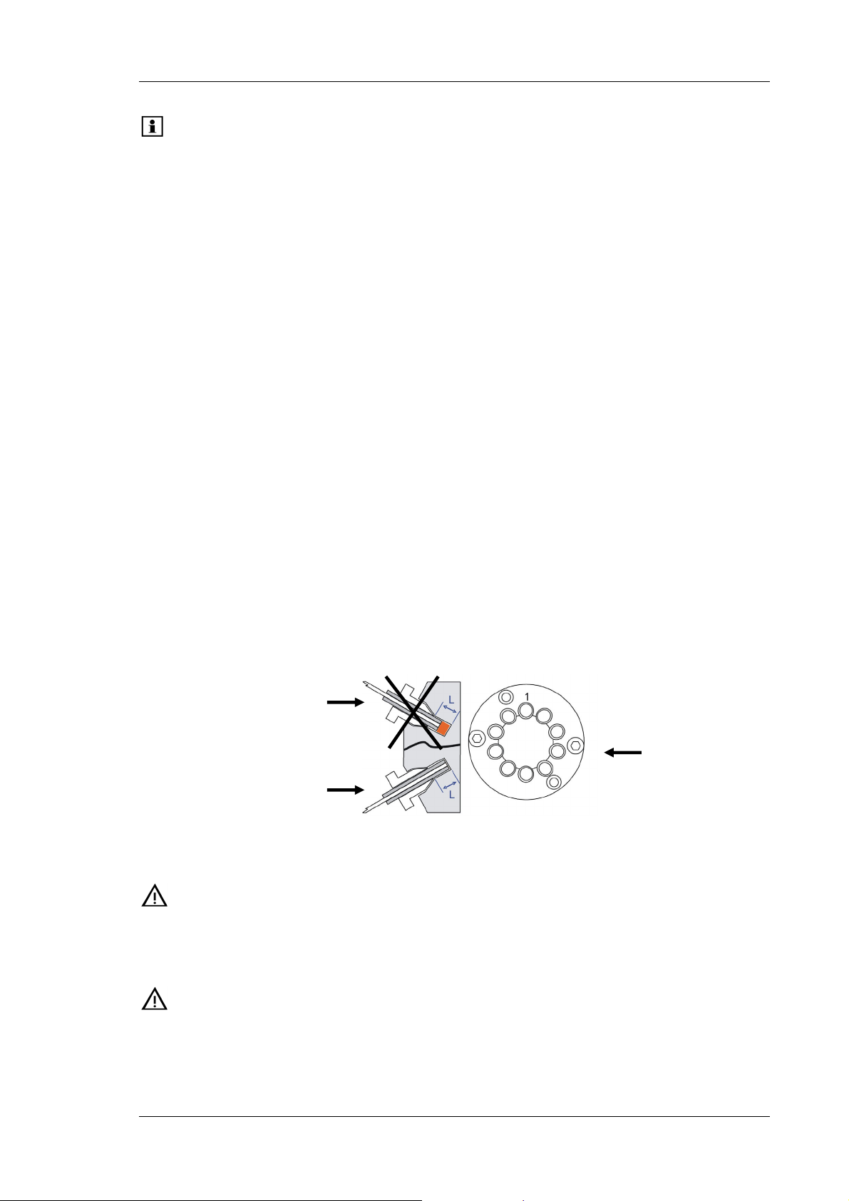
The biocompatible flow managers are fitted with PAEK switching valves. As PAEK valves
have deeper connection ports (→ Fig. 2), preassembled fitting connections (see below) must
be used. This is essential for a zero dead volume connection.
Fitting not
preassembled correctly
Switching valve
Fitting
preassembled correctly
Fig. 2: Capillary connection on the switching valve
Important: Do not use a stainless steel nut and/or ferrule to connect the
components to the PAEK valve. To avoid damage to the valve, use only
the supplied capillaries and fittings, as well as original Dionex spare
parts.
Important: N’utilisez jamais de vis et/ou ferrules métalliques pour les connexions
sur une vanne biocompatible en PAEK. Afin d’éviter tout dommage à
la vanne, utilisez seulement les capillaires et raccords fournis, ainsi que
des pièces d’origine Dionex.
Operating Instructions Page 13
Page 20
UltiMate 3000 Series: Flow Managers and Column Thermostats
Follow the steps below to connect the components to the biocompatible switching valve.
The description refers to the connection of a nano column, but applies to the other
components, as well.
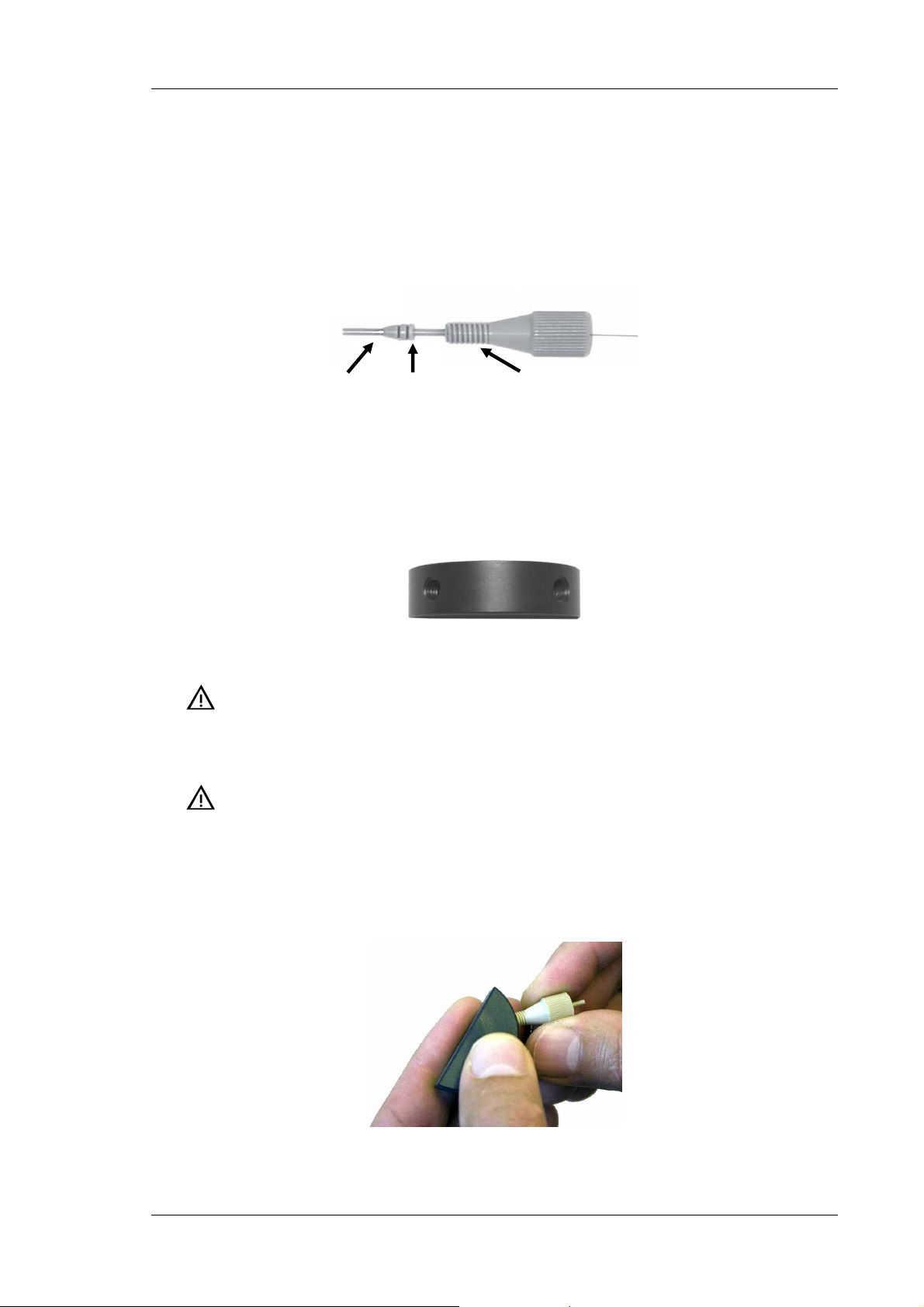
1. To establish a zero dead volume fitting connection between the column and the
switching valve, a finger-tight nut, ferrule, and sleeve are required. Slide the fingertight nut and the ferrule onto the sleeve as shown in Fig. 3.
Column
Sleeve Finger-tight nut Ferrule
Fig. 3: Fitting connection
2. Insert the sleeve with the nut and the finger-tight nut in a port on the preassembly tool
(part no. 6000.0065) and tighten the nut by two or three manual turns. (The
preassembly tool is included in the application kits for the biocompatible UltiMate
3000 system.)
Fig. 4: Preassembly tool
Important: To avoid damage to the biocompatible switching valve, neither
preassemble the fitting connection on the switching valve nor use
any tool to tighten the finger-tight nut.
Important: Afin d’éviter tout dommage à la vanne d’injection biocompatible,
ne l’utilisez jamais pour le pré-sertissage des raccords, et n’utilisez
aucun outil pour visser les raccords à serrage manuel.
3. Push the sleeve all the way into the port. It is essential for a zero dead volume
connection that the assembly seats firmly.
Fig. 5: Preassembling the fitting connection
Page 14 Operating Instructions
Page 21
UltiMate 3000 Series: Flow Managers and Column Thermostats
4. Tighten the nut in the port until it is finger tight.
5. Carefully turn the nut an additional 1/4 turn (90°) past the point at which the ferrule
starts to grab the sleeve.
Tip: Dionex cannot provide a torque specification because the force
required to tighten the nut can vary due to the friction between nut
and the thread, as well as the composition and wall thickness of the
component to be connected.
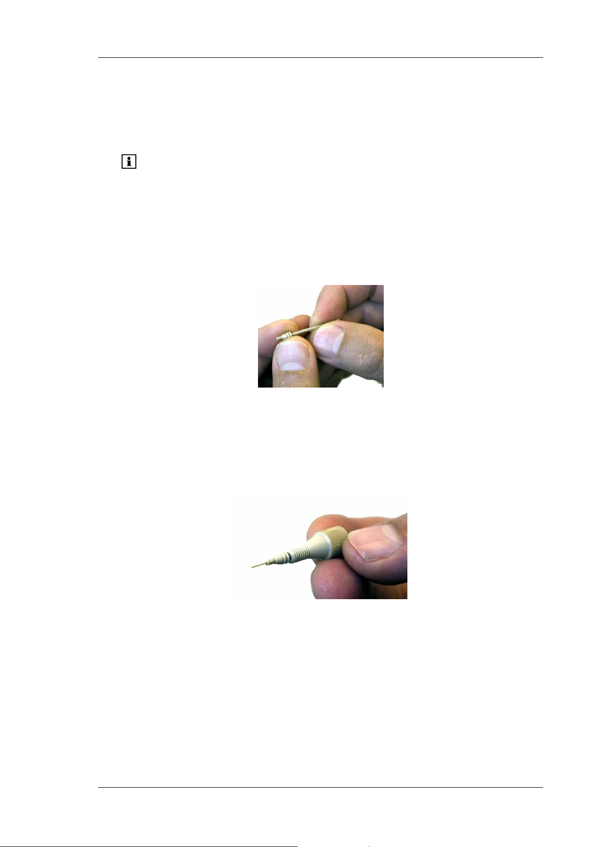
6. Remove the preassembled fitting from the tool and inspect the fitting. When you
gently pull the ferrule, you should not be able to move the ferrule on the sleeve. If the
ferrule sleeve moves laterally (→ Fig. 6), re-insert the fitting all the way into the
preassembly tool and tighten it an additional 1/8 turn past finger-tight.
Fig. 6: Inspecting the fitting
7. Remove and re-inspect the fitting. Repeat the previous step if necessary.
8. Insert the column (or the fused silica capillary) all the way through the sleeve until it
extends the sleeve (→ Fig. 7).
Fig. 7: Inserting the column
Operating Instructions Page 15
Page 22
UltiMate 3000 Series: Flow Managers and Column Thermostats
9. Pull the column back (→ Fig. 8) and install the preassembled fitting with the column
to the appropriate port on the switching valve. Make certain that the column does not
extend the sleeve when installing it into the port
Fig. 8: Pulling the column back
10. Tighten the nut finger-tight. To avoid the formation of dead volumes, make certain
that the column inlet enters all the way to the bottom of the valve port (e.g. push the
column into the valve).
11. Tighten the nut additional 1/4 turn past finger-tight.
12. Start flow delivery and check for leakage. In case of any leakage, stop flow delivery
and remove the fitting. Repeat steps 8 till 11.
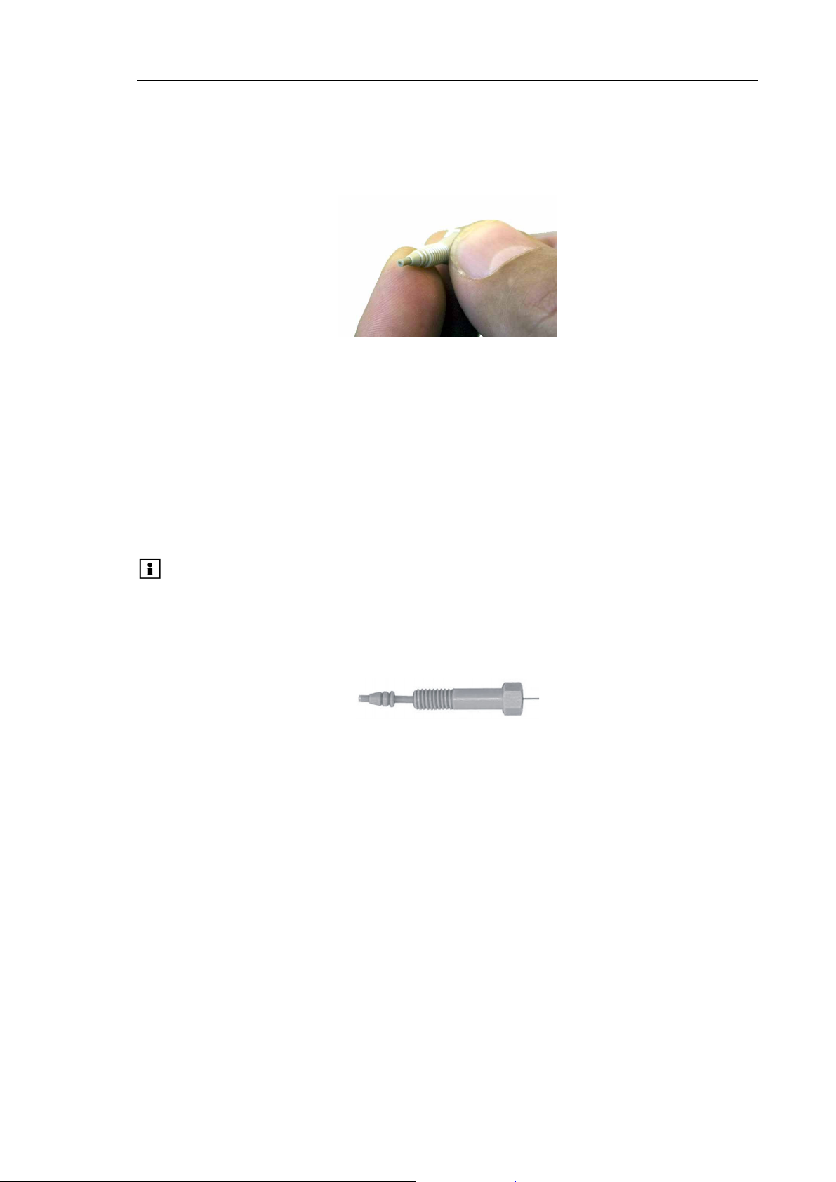
Tip: If you cannot use finger-tight fittings due to limited space, you may use the
long hex style nuts, instead (→ Fig. 9; part no. 6721.0017; the nuts are
included in the application kits for the biocompatible UltiMate 3000 system,
also). Follow the above steps and then connect the hex nut to the
appropriate port on the switching valve. Tighten the nut with a ¼" wrench.
Fig. 9: Long hex style nut
Page 16 Operating Instructions
Page 23
UltiMate 3000 Series: Flow Managers and Column Thermostats
2.4 General Flow Manager Design
7
7
5 5 6
5 5 6
1 2 3 4
1 2 3 4
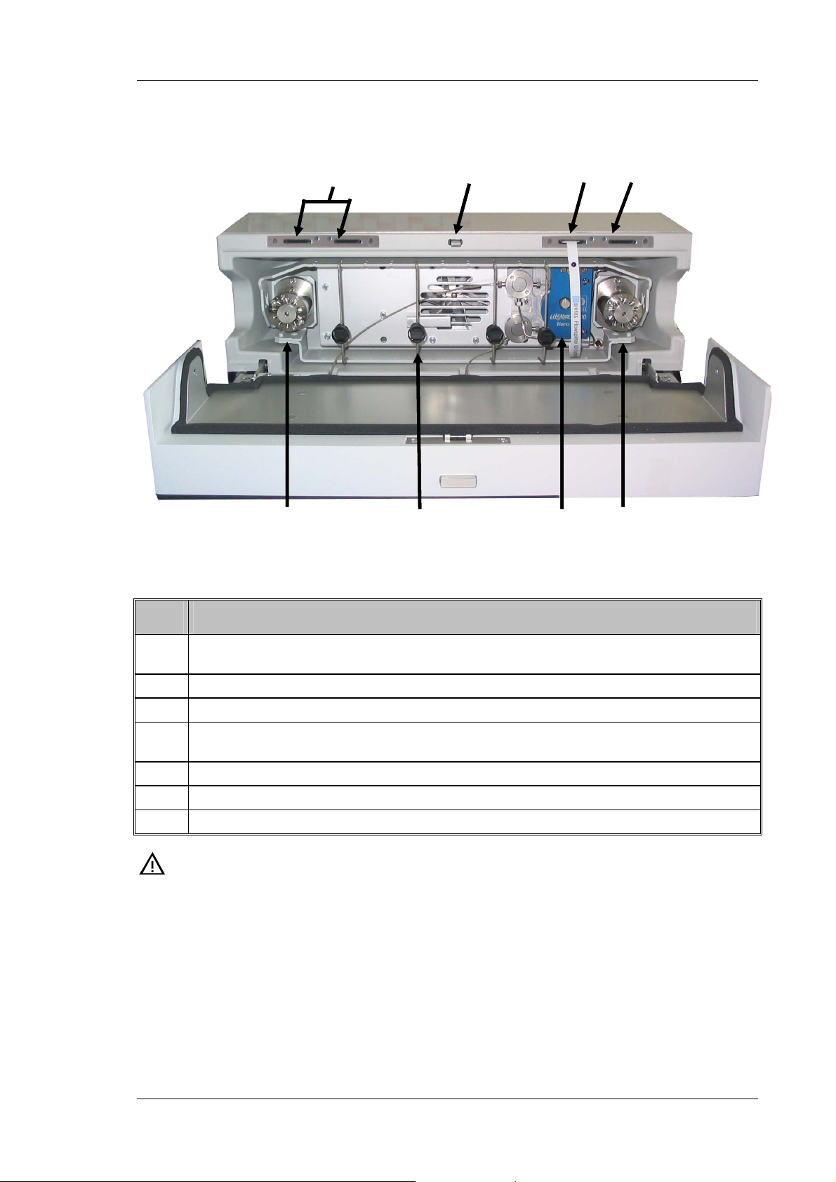
Fig. 10: Open FLM-3100 (here: with two 2-position/10-port switching valves)
No. Description
1 Switching valve (2-position/10-port micro switching valve)
(in Chromeleon: ValveLeft or MsvPosition, depending on the device type)
2
Column bracket with column clip (→ section 3.6.1, page 31)
3
Flow splitter (→ section 7.6, page 76)
4 Switching valve (if installed: 2-position/10-port micro valve or 2-position/6-port nano valve)
(in Chromeleon: ValveRight)
5
Slots for the column ID chip cards (→ section 5.5, page 58)
6
Slot for the flow splitter chip card (→ section 5.6, page 59)
7
Locking mechanism for the front panel door (→ section 3.5, page 28)
Important: Use only the capillaries shipped with the flow manager and original
spare capillaries from Dionex. Install the capillaries and fittings only at
the positions for which they are intended.
Reuse used fittings and ferrules only for the same capillary connection.
This is to avoid increased dead volume.
To connect the capillaries to the switching valve, install only the
ferrules and fitting screws provided in the accessories kit.
Operating Instructions Page 17
Page 24

UltiMate 3000 Series: Flow Managers and Column Thermostats
Important: Utilisez uniquement les capillaires fournis avec l'instrument et les
capillaires de rechange d'origine Dionex. Installez les capillaires et les
raccords uniquement dans les positions pour lesquelles ils sont prévus.
La réutilisation des raccords et ferrules n’est possible que pour la
connexion capillaire d’origine, afin d’éviter l’apparition de volumes
morts.
Pour brancher les capillaires à une vanne d'injection, installez
uniquement les ferrules et les raccords livrés avec la vanne et respectez
les instructions d'installation du fabricant.
2.5 Column Switching Valve
Depending on the instrument configuration, the flow manager is equipped with one or two
switching valves (2-position/10-port micro and/or 2-position/6-port nano valves), e.g., for
applications that require different columns at frequent intervals at similar temperatures.
The switching valve automatically selects the column to be used. The valve is installed in the
column chamber and is brought to the temperature equilibrium as well. The valve positions are
programmed and controlled in Chromeleon. (For details, refer to the Chromeleon online
Help.)
For information about how to connect the capillaries to the valve, refer to Connecting the
Capillaries to the Column Switching Valve (→ page 35).
For more information about the valve, refer to the technical appendix (→ page 91).
Page 18 Operating Instructions
Page 25
UltiMate 3000 Series: Flow Managers and Column Thermostats
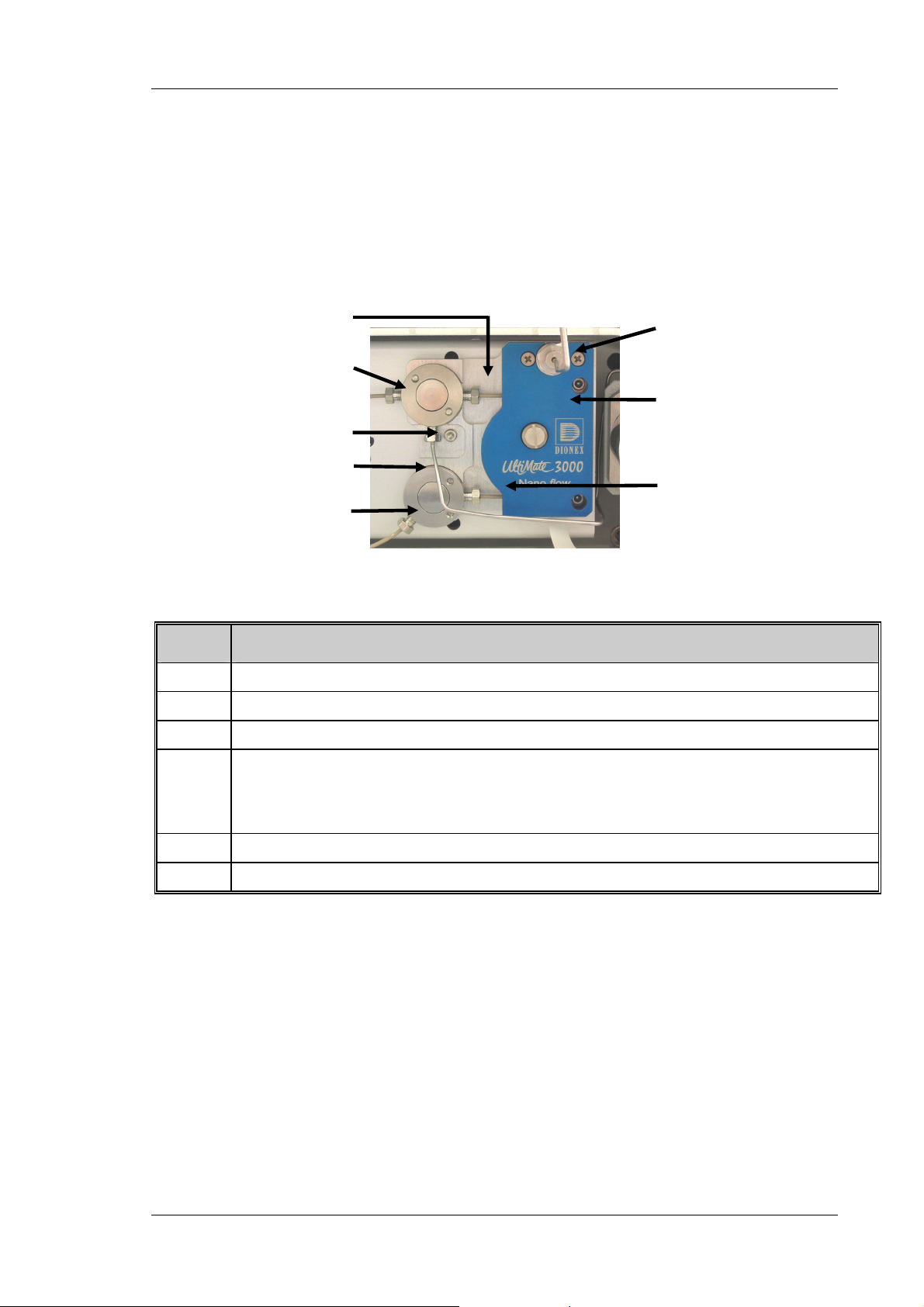
2.6 Flow Splitter
The flow manager is equipped with a flow splitter (→ Fig. 11) that delivers the low flow
rates required for nano, capillary, and micro HPLC applications. Splitter cartridges with
different split ratios are available for the different applications.
For information about the cartridge types and installation details, refer to section 7.6
(→ page 76).
1
2
3
4
2
6
5
1
Fig. 11: Flow Splitter
No. Description
1 Splitter cartridge outlets
2 Flow sensor connectors
3 Flow control valve connector
4 Capillary connector, depending on your application. (The nano (capillary or micro) flow set in
Chromeleon is output here.)
For the application shown in Fig. 24 (→ page 35), connect the capillary to the flow manager's
right switching valve (port 4).
5 Splitter cartridge
6 Pump connector
Operating Instructions Page 19
Page 26
UltiMate 3000 Series: Flow Managers and Column Thermostats
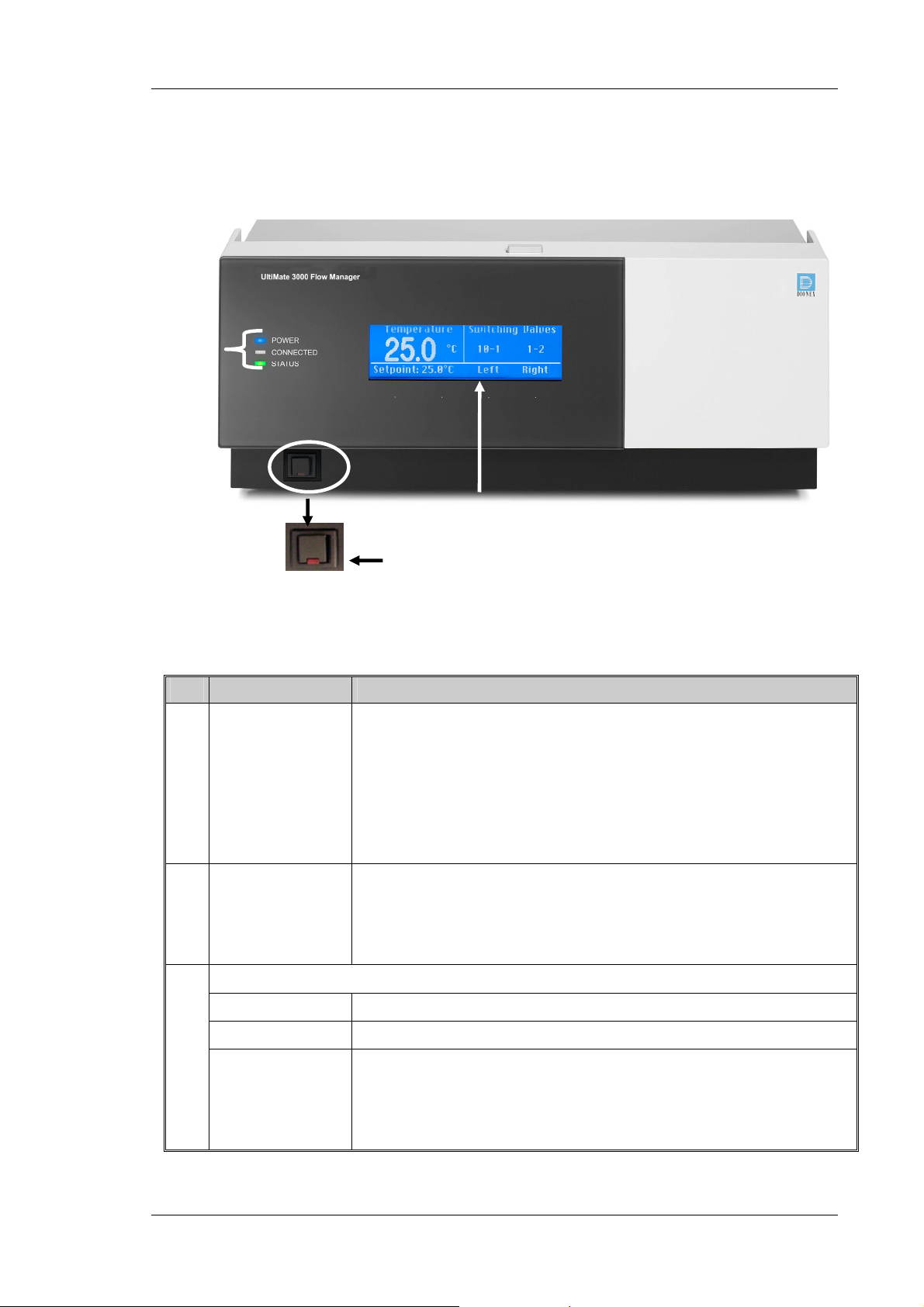
2.7 Front Panel Display and Controls
3
1
2
Fig. 12: Front panel
No. Front Panel Element Description
1 Display Shows information about the flow manager, e.g.:
- General information upon power-up (→ section 4.1, page 41)
- Status screen (→ section 4.2, page 41)
- Various functions and menus that can be accessed via soft keys
(→ section 4.3, page 42)
- Error messages (→ section 6, page 61)
2 Standby button Switches the flow manager to Standby mode (the LED is lighted).
To cancel Standby mode and resume operation, press the Standby button
again (the LED is not lighted).
Note: To allow the flow manager to change the mode, press the Standby
button for at least 1 second.
3
LEDs
Power The LED is blue when the flow manager is on.
Connected The LED is green when the flow manager is controlled by Chromeleon.
Status The LED is green when the flow manager has reached the target temperature
and no error has been detected.
The LED is orange when the flow manager has not yet reached the target
temperature or when the door is open.
The LED is red when an error has been detected, e.g., a leak.
Page 20 Operating Instructions
Page 27
UltiMate 3000 Series: Flow Managers and Column Thermostats
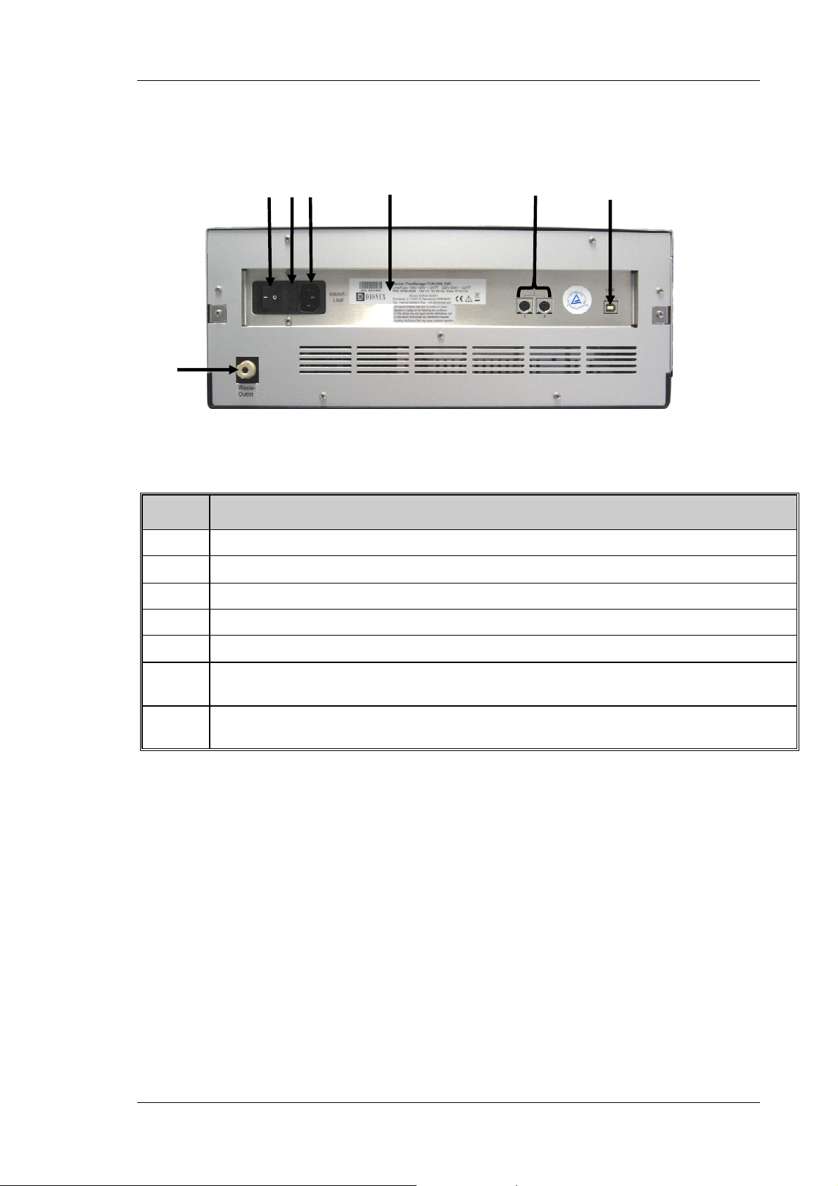
2.8 Rear Panel Connectors
1
3
2
4
7
Fig. 13: Rear panel connectors
No. Description
1 Power switch
2
Fuse holder (→ section 7.3, page 72)
6 5
3 Main power receptacle
4 Type label
5
6 USB (Universal Serial Bus Interface) port for connection to the server PC
7 Waste port for directing any liquid from the waste path of the flow splitter to an appropriate waste
Digital I/O for communication with external devices (→ section 3.4.3, page 28)
(→ section 3.4.1, page 27)
container, page 30)
Operating Instructions Page 21
Page 28

UltiMate 3000 Series: Flow Managers and Column Thermostats
2.9 Leak Sensors
The flow manager contains two leak sensors to detect any humidity or gases that may
accumulate in the column chamber. When a certain humidity or gas concentration is
reached in the chamber (while the door is closed), the corresponding sensor is activated.
Eliminate the cause for the leakage, wearing the appropriate protective clothing, and
ventilate the inside before closing the door.
In addition, the flow manager contains a fluid leak sensor to detect liquid leaks from the flow
control valve in the enclosure. The fluid leak sensor is installed in the rear of the enclosure (in
a tray on the right). When liquid is detected in tray, e.g., due to clogging of the waste outlet
(→ Fig. 18, page 30), the sensor is activated. Eliminate the cause for the leakage and dry the
sensor as described in section 7.5 (→ page 74).
On the Control > Leak control display menu (→ page 46), set the sensitivity for the sensors
and determine whether an acoustic beep shall alert you in case of an alarm. (You can open the
Leak control display menu also via the Leak soft key (→ page 42).)
If one of the sensors detects a leak, the Status LED on the instrument's front panel is red and
the related error message appears on the front panel display.
Tips: The Status LED remains red as long as the sensor is exposed to humidity,
gas, or moisture. The Clear soft key on the navigation bar (→ page 45)
allows you to remove the error message from the front panel display.
If a beep alerts you, you can turn off the beep for the current alarm from the
Control > Leak control display menu by setting All leak alarms to silent. If
the humidity or gas sensor was activated, you can turn off the alarm also by
opening the front panel door. Beeping stops in any case when the cause for the
leakage has been eliminated. A new beep sounds when one of the sensors is
activated again.
If the flow manager is operated by Chromeleon, you can also determine the
leak sensor mode in Chromeleon. If a sensor is activated, the related error
message appears on the front panel display and the error is logged in the
Chromeleon audit trail.
Inspect the flow manager for leaks every day. Tighten or replace leaking
capillary connections if necessary.
Page 22 Operating Instructions
Page 29

UltiMate 3000 Series: Flow Managers and Column Thermostats
2.10 System Wellness
The flow manager supports several system wellness and reliability features that can help
you detect small problems before they turn into big ones:
• Leak detector (→ page 21)
• Door status monitoring
• Column ID features for a GLP-compliant documentation of the column status
(→ Column Identification System (Column ID), page 58)
• Flow splitter ID for the documentation of the splitter type and characteristics
(→ Splitter Identification System (Splitter ID), page 59)
Tip: If the flow manager is operated by Chromeleon, the system wellness features
are also available in Chromeleon (→ Diagnostics, page 60).
If an error is found, the Status LED on the front panel is red and an error message appears
on the front panel display (→ Troubleshooting, page 61). If the flow manager is operated
by Chromeleon, the error is also logged in the Chromeleon Audit Trail.
Operating Instructions Page 23
Page 30

UltiMate 3000 Series: Flow Managers and Column Thermostats
Page 24 Operating Instructions
Page 31

UltiMate 3000 Series: Flow Managers and Column Thermostats
3 Installation
3.1 Facility Requirements
• Make sure that the installation site meets the power and environmental specifications
listed in the Technical Information section (→ page 83).
• Install the instrument in the laboratory on a stable surface that is free of vibrations.
• Make sure that the surface is resistant to solvents.
• Avoid locations with extreme changes in temperature (such as direct sunlight or drafts)
and high humidity.
• Allow sufficient clearance behind and to the sides of the flow manager for power
connections and ventilation. Do not place any objects between the flow manager and the
device located under the it in the system stack.
3.2 Unpacking
All electrical and mechanical components of the flow manager are carefully tested before
the instrument is shipped from the factory. After unpacking, please inspect the module for
any signs of mechanical damage that may have occurred during transit.
Tips: Immediately report any shipping damage to both the incoming carrier and
Dionex. Shipping insurance will compensate for the damage only if reported
immediately.
Keep the original shipping container and packing material. They provide
excellent protection for the flow manager in case of future transit. Shipping the
instrument in any other packaging automatically voids the product warranty.
1. Place the shipping container on the floor. Remove the accessories kit and power cord.
2. Grasp the flow manager by the sides. Slowly and carefully, pull the instrument out of
the shipping container and place it on a stable surface.
Important: To prevent the flow manager from falling, only lift by the bottom
sides. Do not lift the unit by the packaging material or the front
panel door. When lifting or moving the flow manager, always lift it
by the bottom or sides of the unit.
Important: Afin d'empêcher l'instrument de tomber, saisissez-la par les côtés.
Ne soulevez l'instrument à l’aide du matériau d'emballage ou par la
porte du panneau avant. Lorsque vous soulevez ou déplacez
l'instrument, soulevez toujours par le bas ou les côtés.
3. Remove the foam inserts.
Operating Instructions Page 25
Page 32

UltiMate 3000 Series: Flow Managers and Column Thermostats
ger
r
4. Before connecting the flow manager to the power supply, wait approximately 4 hours
to allow the instrument to come to room temperature and to allow any condensation
that might have occurred during shipping to evaporate. After 4 hours, check the flow
manager; if condensation still exists, allow the flow manager to continue to warm up
(without connecting it to the power source) until the condensation is completely gone.
3.3 Positioning the Flow Manager in the UltiMate 3000 System
As the flow manager is part of an UltiMate 3000 system, Dionex recommends that you stack
the individual modules, for example, as shown in Fig. 14. However, the arrangement of the
system modules depends on the application. The UltiMate 3000 Proteomics MDLC system
manual in this manual binder provides more application examples and information about how
to arrange and/or connect the modules for these applications.
Solvent Rack
Detecto
Flow Mana
Autosampler
Pump
Fig. 14: Example for an UltiMate 3000 system
Page 26 Operating Instructions
Page 33

UltiMate 3000 Series: Flow Managers and Column Thermostats
3.4 Connecting the Flow Manager
3.4.1 USB
The Chromeleon Chromatography Management System can use a USB connection to
control the flow manager. Data is transferred digitally via the appropriate USB cable (part
no. 6911.0002, USB extension cable, part no. 6000.1005). To ensure trouble-free
operation, all USB cables (see above) should be ordered from Dionex.
Tip: If you want to operate the flow manager with Chromeleon, install the
Chromeleon software before connecting the flow manager to the USB port on
the Chromeleon server PC. When you install the Chromeleon software first, the
USB driver for the flow manager is automatically loaded and the Windows
operating system can detect the flow manager when the power is turned on.
Connect the flow manager to the server PC via the USB ports on the rear panel (→ Fig. 13,
page 21). To do so, select one of the following alternatives:
• Connect the flow manager directly to the USB port on the server PC.
• Connect the flow manager to the server PC via another UltiMate 3000 instrument that is
already connected to the server PC.
• Connect the flow manager to server PC via an external USB hub.
Tip: The USB standard limits the USB cable length to 5 meters. Each USB
device can be separated from the PC or next USB hub by no more than
5 meters.
Important: Dionex recommends using these USB ports for connections to Dionex
instruments only. Dionex cannot guarantee correct functioning if
instruments from other manufacturers are connected.
Important: Dionex recommande d'utiliser les ports USB uniquement pour les
raccordements aux instruments Dionex. Dionex ne peut garantir le bon
fonctionnement si les instruments d'autres fabricants sont raccordés.
3.4.2 Power Connection
Use the power cord shipped with the flow manager to connect the instrument to the main
power source. Connect the power cord from the main power receptacle on the rear panel to
the power source that is connected to a true ground. No adjustment is required to adapt the
line voltage to local voltage requirements.
Operating Instructions Page 27
Page 34

UltiMate 3000 Series: Flow Managers and Column Thermostats
3.4.3 Digital I/O
The two 6-pin Mini-DIN (→ Fig. 13, no. 5) ports can be used in Chromeleon to exchange
digital signals with external instruments. The accessories kit includes a 6-core Mini-DIN
signal cable (part no. 6000.1004). For information about the port and pin assignment, refer
to the technical appendix (→ page 91).
3.5 Opening the Front Panel Door
The front panel tilts downward to provide easy access to the components in the column
chamber. Tilting down the front panel automatically moves the valves and the column
carrier approximately 3.5 cm out of the enclosure, thus facilitating capillary connection.
To open the front panel door, press the release button on top of the enclosure. If the door lock
is not released immediately, press the front panel against the enclosure.
If necessary, press
here against the
Press the release
button.
Locking mechanism for the front panel door
Fig. 15: Tilting the front panel downward
To close the column chamber, tilt the front panel upward until you hear the locking
mechanism engage.
Important: When lifting or moving the flow manager, always lift the unit by the
bottom sides or the sides. Lifting the flow manager by the bottom front
or by the front panel may damage the door.
Do not place any heavy objects on the open front panel door. This may
damage the door.
Important: Lorsque vous soulevez ou l’instrument, tenez-le toujours par le dessous
ou par les côtés de l'unité. Soulever l’instrument par la partie avant
inférieure ou par le panneau avant peut endommager la porte.
Ne placez aucun objet lourd sur la porte ouverte du panneau avant. Ceci
pourrait endommager la porte.
Page 28 Operating Instructions
Page 35

UltiMate 3000 Series: Flow Managers and Column Thermostats
3.6 Preparing the Flow Manager
Important: The flow manager is filled with a mixture of isopropanol and water
(20:80) when being shipped from the factory. During initial operation,
make sure that the solvents used are miscible. Otherwise, use an
appropriate intermediate solvent.
When you operate a biocompatible flow manager, observe the
instructions for connecting the capillaries to the switching valve and/or
flow splitter (→ Biocompatible Flow Managers, page 13).
Important: L'instrument est stocké sous isopropanol et eau. Au cours démarrage de
l'instrument, assurez-vous que les solvants utilisés soient miscibles.
Sinon, suivez les étapes intermédiaires appropriées.
Afin de raccorder les capillaires à la vanne d'injection ou au diviseur de
débit biocompatible, veuillez respecter les instructions d'installation
(→ Biocompatible Flow Managers, page 13).
After you have unpacked, positioned and connected the flow manager as described in
sections 3.1 through 3.4, follow the steps below to prepare the flow manager for operation.
1. Connect a drain tubing to the two ports at the bottom right of the instrument (→ Fig.
16) to direct condensing water and/or liquid leaks to an appropriate waste container.
Drain port
(2 ports at the bottom right
of the flow manager)
Fig. 16: Drain port
Important: The drain tube must remain below the drain port. If the drain tube is
above the drain port, the liquid may flow back into the interior and
cause damage to the instrument. Also, be careful not to use tubing
that is bent.
Important: Afin d'éviter d'endommager l'instrument, assurez-vous qu'aucune
pièce des tubes n'est placée plus haute que le port de raccordement.
Operating Instructions Page 29
Page 36

UltiMate 3000 Series: Flow Managers and Column Thermostats
Wrong Correct
Fig. 17: Connecting the drain tubing
Tip: As the flow manager is part of an UltiMate 3000 system for nano
and cap HPLC applications, you may connect the drain tubing of the
system modules with the connecting pieces from the devices'
accessories kits. For more information, refer to the UltiMate 3000
Proteomics MDLC system manual.
2. Connect a waste tubing to the waste port on the instrument's rear panel (→ Fig. 18) to
direct any liquid from the waste path of the flow splitter to an appropriate waste
container. Dionex recommends connecting, for example, PTFE tubing with an inner
diameter of 1 mm (minimum 0.5 mm). Make sure that the tubing is long enough to
reach the bottom of the waste container.
Waste port
Fig. 18: Waste port
(on the rear panel)
Important: Make sure the waste port and waste tubing are not blocked during
operation of the flow manager and that the tubing is not bent.
For optimum chromatographic results, you should not change the
position of the tubing and/or the waste container during the analysis
or direct the liquid to a capped waste container because this might
impair flow control performance.
Important: Assurez-vous que la tubulure d’évacuation (Waste) est libre en
toutes circonstances. Vérifiez que les tubes ne sont ni pliés, ni
bouchés.
Pour des résultats chromatographiques optimaux, vous ne devez ni
modifier les positions de la tubulure d’évacuation et du flacon egout
pendant l'analyse, ni diriger le liquide dans un récipient
hermétiquement clos; ceci risque d'affecter les performances du
contrôle du débit.
Page 30 Operating Instructions
Page 37

UltiMate 3000 Series: Flow Managers and Column Thermostats
3. Install the column(s) as described in Installing a Separation Column (→ page 31).
4. Install the column(s) as described in Installing a Trap Column (→ page 36).
5. Establish the fluid connections between the column(s), switching valve(s), and flow
splitter according to your application. For information about the connections on the
column switching valves, refer to section 3.6.2 (→ page 35). For information about the
connections on the flow splitter, refer to section 3.6.4 (→ page 37).
6. Connect the flow manager to the other components of your UltiMate 3000 system, as
required by your specific application.
Tip: For information about how to connect the system modules and for
application examples, refer to the UltiMate 3000 Proteomics MDLC
system manual.
7. Turn on the instrument by pressing the power switch on the rear panel.
Tip: The noise that is heard for a few seconds after turning on the flow manager
is normal and does not impair the flow manager's performance.
When the flow manager is powered up, the following information appears on the front
panel display: Device type, serial number, and firmware version. After some seconds, the
initial screen changes to the status screen (→ page 41).
8. Install the flow manager in Chromeleon as described in section 5 (→ page 49).
3.6.1 Installing a Separation Column
Warning: Before carrying out any work in the column chamber, wait for the
column chamber to cool down. Do not touch any metal parts inside
the column chamber while the temperature set point is > 50 °C (122
°F).
Avertissement: Avant de procéder à toute modification dans le compartiment de
colonne, attendez que celui-ci refroidisse. Ne touchez aucune partie
en métal à l'intérieur du four, tant que l’affichage de la température
est > 50 °C (122 °F).
Four column brackets are installed in the column chamber at the factory. Attach the
columns to the brackets using the special column clips from the accessories kit.
1. The column clip consists of two pieces.
To remove the ring from the bottom part, slightly press the ring in the direction of the
arrows, which are printed on the ring.
Operating Instructions Page 31
Page 38

UltiMate 3000 Series: Flow Managers and Column Thermostats
Press the ring in the
direction indicated by the
arrows on the ring.
Fig. 19: Two-piece column clip
2. When installing the column clips for the first time: the kit includes self-adhesive foam
pads to protect the column. Place one pad on the inner side of the bottom part of each
clip.
3. Attach the bottom part of the clip to the bracket and turn it 90° clockwise.
Attach the bottom part of the
clip to the bracket and turn it
90° clockwise.
Fig. 20: Installing the bottom part
4. If you want to use column identification
Attach the column ID chip card to the column. Two chip cards are provided in the
accessories kit. Wrap the ribbon around the column, pass the shank of the rivet
through a hole, and press down to unite the two parts (→ section 5.5, page58).
Page 32 Operating Instructions
Page 39

UltiMate 3000 Series: Flow Managers and Column Thermostats
5. Press the column into the clip and reinstall the ring.
Fig. 21: Installing a column in the clip
6. Connect the capillaries to column.
Tip: For information about the connections on the column switching
valve(s), refer to section 3.6.2 (→ page 35). For information about the
connections on the flow splitter, refer to section 3.6.4 (→ page 37).
You can guide the capillaries out of the interior at any position between the enclosure
and the front panel door. To thread the capillaries out of the interior on the left or right
side of the enclosure, direct them through the respective capillary guide.
Capillary guide
Fig. 22: Capillary guide installed on the carrier
Dionex recommends guiding the capillaries out of the interior in such a way that the
connections are as short as possible.
Operating Instructions Page 33
Page 40

UltiMate 3000 Series: Flow Managers and Column Thermostats
Tip: Place the capillaries in such a manner (i.e., preferably 90-degree angle
related to the door seal) that they do not open a small path for ambient
air into the column chamber. This will prevent a proper seal and thus,
impair the heating and cooling performance of the flow manager. When
cooling, an improper seal may lead to a considerable amount of
condensed water.
An electronic column identification module allows GLP-compliant
documentation of the column type and the most important column
parameters. For more information, refer to section 5.5 (→ page 58).
You may move the preinstalled brackets as required by your application:
• The bracket for the column clips is installed in the column carrier as shown in Fig. 23. To
remove the bracket, slightly push it downward. You can now remove the bracket at the
top. Then, remove it at the bottom of the carrier. To install the bracket at the new position,
proceed in the reverse order.
Bracket installed in
the column carrier.
Slightly push the bracket
downward.
Fig. 23: Bracket installed in the column carrier
Page 34 Operating Instructions
Page 41

UltiMate 3000 Series: Flow Managers and Column Thermostats
3.6.2 Connecting the Capillaries to the Column Switching Valve
Depending on the instrument configuration, the flow manager is fitted with one or two
column switching valves (2-position/10-port or 2-position/6-port). Valve switching is
programmed and controlled via Chromeleon. (For more information, refer to the
Chromeleon online Help.) Establish the fluid connections:
1. Remove the plastic cap that protects the switching valve during shipment.
2. Connect the capillaries, using an appropriate tool. For an example, refer to Fig. 24.
Important: When you operate a biocompatible flow manager, observe the
instructions for connecting the capillaries to the switching valve
(→ page 13).
Important: Afin de raccorder les capillaires à la vanne d'injection biocompatible,
veuillez respecter les instructions d'installation (→ page 13).
from
pump
to
detector
2
3
4
5
1
1-2
1-10
6
Wast e
FLM-3100
10
9
8
7
Waste
from
autosampler
n
1
2
10
3
4
5
1-2
1-10
6
9
8
7
Separation column
Flow splitter
m
u
l
o
c
e
r
p
Port Connect the capillary ….
1 from the autosampler
2 to the trap column
3 to the separation column
4 from the flow splitter
5 from the trap column
6 to the waste
7-9 Not used
10 To the waste
Fig. 24: Example for the connections on a 2-position/10-port column switching valve
Operating Instructions Page 35
Page 42

UltiMate 3000 Series: Flow Managers and Column Thermostats
Important: To connect the capillaries to the switching valve, install only the
ferrules and fitting screws provided in the flow manager's accessories
kit.
Important: Pour raccorder les capillaires à la vanne d'injection, installez
uniquement les ferrules et les raccords fournis dans le kit d'accessoires.
3.6.3 Installing a Trap Column
Warning: Before carrying out any work in the column chamber, wait for the
column chamber to cool down. Do not touch any metal parts inside
the column chamber while the temperature set point is > 50 °C (122
°F).
Avertissement: Avant de procéder à toute modification dans le compartiment de
colonne, attendez que celui-ci refroidisse. Ne touchez aucune partie
en métal à l'intérieur du four, tant que l’affichage de la température
est > 50 °C (122 °F).
Follow the steps below if your application includes a trap column:
1. To install the trap column a column holder is required.
The application kits for the UltiMate 3000 nano and cap system include a trap column
holder with the appropriate capillaries.
2. Insert the trap column in its holder and connect the capillaries directly to the column
switching valve, e.g., to ports 2 and 5 (→ Fig. 24, page 35) as described in the
UltiMate 3000 Proteomics MDLC system manual in this manual binder.
Important: When you operate a biocompatible flow manager, observe the
instructions for connecting the capillaries to the switching valve
(→ page 13).
Important: Afin de raccorder les capillaires à la vanne d'injection biocompatible,
veuillez respecter les instructions d'installation (→ page 13).
Page 36 Operating Instructions
Page 43

UltiMate 3000 Series: Flow Managers and Column Thermostats
3.6.4 Connecting the Flow Splitter
Important: The flow sensor connectors (→ Fig. 11, no. 2) and the flow control
valve connector (→ Fig. 11, no. 3) are installed in the factory. They
should not be opened by the user.
Important: Les raccordements au capteur de débit (→ Fig. 11, no. 2) et à la vanne
de régulation de débit (→ Fig. 11, no. 3) sont effectués en usine. Ils ne
doivent pas être modifiés par l'utilisateur.
Follow the steps below to connect the capillaries to the flow splitter:
Warning: Before carrying out any work in the column chamber, wait for the
column chamber to cool down. Do not touch any metal parts inside
the column chamber while the temperature set point is > 50 °C (122
°F).
Avertissement: Avant de procéder à toute modification dans le compartiment de
colonne, attendez que celui-ci refroidisse. Ne touchez aucune partie
en métal à l'intérieur du four, tant que l’affichage de la température
est > 50 °C (122 °F).
Important: When connecting the capillaries, make sure that the connectors are
free from contaminants. Even minute particles may cause damage to
the flow splitter, flow control valve, and column.
When you operate a biocompatible flow manager, observe the
instructions for connecting the capillaries (→ page 13).
Important: Lorsque vous connectez les capillaires, assurez-vous que les
raccords sont exempts de tout contaminant. Même d'infimes
particules peuvent causer des dommages au système (ex. diviseur de
débit, vanne de régulation de débit et colonne).
Afin de raccorder les capillaires à la vanne d'injection
biocompatible, veuillez respecter les instructions d'installation
(→ page 13).
Operating Instructions Page 37
Page 44

UltiMate 3000 Series: Flow Managers and Column Thermostats
1. Use the special capillary that is shipped with the Application Kit to connect the flow
manager to the pump (→ Fig. 11, page 19).
Description Part No.
Long capillary for connecting the pump to the flow splitter
(including the appropriate fittings and ferrules)
Standard version
Biocompatible version
Use this capillary, for example, when the system modules are stacked
as shown in Fig. 14 (→ page 26).
Short capillary for connecting the pump to the flow splitter
(including the appropriate fittings and ferrules)
Standard version
Biocompatible version
Use this capillary, for example, when the pump is directly on the flow manager.
6035.2550
6037.2550
6035.2553
6037.2553
Important: Do not substitute the capillaries mentioned in the above table for
any other capillary.
♦ Connect the capillary to the pump. Bend the capillary for connection to the
flow splitter if necessary.
♦ Rinse the capillary with isopropanol, via the pump (maximum flow rate, 5
minutes).
♦ Connect the capillary to the flow splitter (→ pump connector, Fig. 11, no. 6).
Tip: The pump outlet connector and flow splitter are equipped with a filter frit
to catch any particles that might have entered the capillary during
installation. Usually, it is not necessary to change these frits.
2. Establish the connection to the capillary connector (→ Fig. 11, no. 4) as required by
your application. For the system structure shown in Fig. 14, connect the capillary to
the flow manager's right switching valve (port 4; → page 35).
Page 38 Operating Instructions
Page 45

UltiMate 3000 Series: Flow Managers and Column Thermostats
3.7 Manual Injection Port
A manual injection port (→ Fig. 25) is available from Dionex as an option for the flow
manager:
Part No. Description
6720.9007 Manual Injection Port, standard flow manager
6721.9007 Manual Injection Port, biocompatible flow manager
The injection port can be installed if you want to perform the injection manually instead of
using an autosampler.
Fig. 25: Flow Manager with manual injection port
Operating Instructions Page 39
Page 46

UltiMate 3000 Series: Flow Managers and Column Thermostats
Page 40 Operating Instructions
Page 47

UltiMate 3000 Series: Flow Managers and Column Thermostats
4 User Interface
4.1 Power-Up
Use the main power switch on the rear panel to turn the flow manager on and off. The
device type, serial number and firmware version are displayed on the display.
Tips: The noise that is heard for a few seconds after turning on the flow manager
is normal and does not impair the flow manager's performance.
Each time the flow manager power is turned on, the flow manager runs a
series of internal tests. During these self-diagnostics, all of the main
components are checked. If an error is detected, the flow manager is not yet
ready for analysis. The Status LED on the front panel is red and an error
message appears on the front panel display. If the flow manager is operated
by Chromeleon, an error message is also logged in the Chromeleon audit
trail. Turn off the flow manager, take appropriate remedial action
(→ Troubleshooting, page 61), and turn on the flow manager again.
4.2 Status Screen
If the self-test was successful, the initial screen changes to the status screen:
Temperature
°C
Switching Valves
10-1 1-2
23.2
Setpoint: 25.0 °C
Fig. 26: Front panel display (here: for an FLM with two 2-position/10-port switching valves)
On the left side, the current temperature and the target temperature are displayed (in °C).
The information about the column switching valves appears on the right side. The
numerical values indicate the valve position.
Tip: Adjust the screen brightness and/or contrast on the Configuration display
menu (→ page 48).
If the flow manager is operated by Chromeleon, you can adjust the settings
also via the Brightness and Contrast parameters in the Commands dialog
box.
Operating Instructions Page 41
Page 48

UltiMate 3000 Series: Flow Managers and Column Thermostats
4.3 Soft Key Menus
Four soft keys under the front panel display provide access to various menus, allowing you
to perform specific commands directly from the flow manager's front panel. White dots on
the front panel mark the positions of the soft keys. To show the soft key menus, select the
position of a white dot on the front panel display with the Dionex menu pen. The menu pen
(part no. 6300.0100) is included in the accessories kit.
Fig. 27: Showing the soft keys
The bottom status screen line changes to show the Menu, Temp, Valve, and Leak soft
keys:
Temperature
°C
Switching Valves
10-1 1-2
23.2
Menu Valve Leak Temp
Fig. 28: Soft keys
Select a soft key with the menu pen:
Soft Key Description
Menu
Temp
Valve
Leak
Opens the Main menu (→ page 45 )
Opens the Temperature control menu (→ page 46).
Opens the Valve control menu (→ page 46).
Opens the Leak control menu (→ page 46).
Page 42 Operating Instructions
Page 49

UltiMate 3000 Series: Flow Managers and Column Thermostats
Tips: If no option is selected, the original status screen line is restored after
about 5 seconds.
When the flow manager is connected in Chromeleon, front panel input
related to the measurement is disabled to prevent changes to the
operating parameters. (Operating parameters are set to read-only.)
Parameters that do not interfere with the measurement, such as, the
screen brightness or contrast can still be changed.
4.4 Menu Structure and Layout
Fig. 29 shows the menu structure:
Main
1. Control
1. Temperature control
2. Valve control
3. Leak control
2. Information
1. System
2. Valve
3. Temperature
Fig. 29: Menu structure
3. Configuration
1. Reset to factory defaults
2. Display & soft keys
Operating Instructions Page 43
Page 50

UltiMate 3000 Series: Flow Managers and Column Thermostats
∧
In general, the menu layout is as follows:
1
> Control (1..3)
1. Temperature control
2
2. Valve control
3. Leak control
3
No. Description
1 Reports the menu name and the number of items on the menu list.
2 The menu items appear on a list and are numbered consecutively.
The selected item is underlined.
3 Navigation bar (see below)
∨
Fig. 30: Menu layout (here: Control menu)
The selected menu item or parameter determines which soft keys appear on the navigation bar:
Soft Key Description
∧
∨
> Takes you to the next figure in a number. Any decimal point is skipped.
Select Confirms the selection and activates the input field if applicable.
Back Returns you to the previous menu level.
Toggle Toggles between two operating states, e.g., between on and off.
OK Confirms the selection and/or input.
Cancel Cancels the action and restores the last value.
Note: Depending on the selected option, specific soft keys may replace these general soft keys.
- Returns you to the previous entry on a list. If the list contains 5 or more items, the arrow
up key can be used to page through the entries on the list (after reaching the first line)
(→ Key autorepeat, page 48).
- Increments numerical values.
- Toggles between operating states e.g., on and off.
Takes you to the next entry on a list. If the list contains 5 or more items, the arrow up key
can be used to page through the entries on the list (after reaching the first line) (→ Key
autorepeat, page 48).
- Toggles between operating states, e.g., on and off.
Note: If an item is read-only (e.g., because the device is connected in Chromeleon), the
Select key will not be available.
Select Back
Page 44 Operating Instructions
Page 51

UltiMate 3000 Series: Flow Managers and Column Thermostats
∧
Tip: If an error is found, one or more error messages appear on the front
panel display. In this case, the following soft keys appear on the
navigation bar:
Soft Key Description
Prev Returns you to the previous error message.
Next Takes you to the next error message.
Clear Remove an error message from the display.
4.4.1 Main Menu
Open the Main menu from the bottom line of a status screen (→ Fig. 28, page 42). To do
so, select the Menu soft key. The Main menu provides top-level access to the menu
structure:
> Main (1..3)
1. Control
2. Information
3. Configuration
∨
Select an item with the arrow up or down key—the selected item is underlined. Confirm your
selection with Select. Back returns you to the status screen.
For information about the menus, refer to:
• Control menu (→ page 46)
• Information menu (→ page 47)
• Configuration menu (→ page 48)
Fig. 31: Main menu
Select Back
Operating Instructions Page 45
Page 52

UltiMate 3000 Series: Flow Managers and Column Thermostats
∧
4.4.2 Control Menu
On the Control menu, you can make the temperature and valve settings. In addition, you
can determine the behavior for a leak alarm:
> Control (1..3)
1. Temperature control
2. Valve control
3. Leak control
∨
Menu Item Description
Temperature control Determine the setpoint temperature and turn temperature control on or off.
Valve control Determine the valve position of the related valve.
Leak control Determines if and how the corresponding sensor responds to gas, humidity or
leaks and how you are alerted in case of an alarm:
Low, standard, or high—enables leak detection and sets the sensitivity with
which the sensor responds. When the sensor responds, a message appears on the
front panel display and an acoustic beep sounds.
Low silent, standard silent, or high silent— enables leak detection and sets the
sensitivity with which the sensor responds. When the sensor responds, a message
appears on the front panel display, but no
Off—disables leak detection.
Fig. 32: Control menu
Select Back
beep sounds.
Page 46 Operating Instructions
Page 53

UltiMate 3000 Series: Flow Managers and Column Thermostats
∧
4.4.3 Information Menu
The Information menu provides general information about the flow manager, e.g., for
diagnostic purposes:
> Information (1..3)
1. System
2. Valve
3. Temperature
∨
Menu Item Description
System Shows general information about the flow manager,
e.g., firmware version, serial number, operating hours, etc.
Valve Shows general information about the switching valves,
e.g., configuration, switching cycle counter, etc.
Temperature Shows general information about the temperature
e.g., working load and cooling load, hours that the flow manager was operated in
a certain temperature range, etc.
Fig. 33: Information menu
Select Back
Operating Instructions Page 47
Page 54

UltiMate 3000 Series: Flow Managers and Column Thermostats
∧
4.4.4 Configuration Menu
The Configuration menu provides information about the instrument configuration and/or
allows you to the make the related settings:
> Configuration (1..2)
1. Reset to factory defaults
2. Display & soft keys
∨
Menu Item Description
Reset to factory defaults
Display & Soft keys Sets the display and soft key parameters:
Select to restore the Dionex standard settings. The Reset to factory
defaults? dialog is opened. To confirm the restore, select OK. Else, select
Cancel.
Brightness— Sets the screen brightness.
Contrast— Sets the screen contrast.
Key sound— Sets whether an acoustic beep sounds when you select a soft
key.
Key autorepeat—Sets wether the arrow up and arrow down keys can be
used to page through the items on a menu list if the list contains 5 or more
entries: On—yes or Off—no.
Fig. 34: Configuration menu
Select Back
Page 48 Operating Instructions
Page 55

UltiMate 3000 Series: Flow Managers and Column Thermostats
5 Software Control by Chromeleon
5.1 General
The flow manager can be controlled by the Chromeleon Chromatography Management
System. To control the flow manager, an appropriate Chromeleon version and a Timebase
Class 1 Chromeleon license are required. (If you have any questions, please contact your
Dionex sales representative.)
Tip: The descriptions below refer to Chromeleon 6.80 Service Pack 2.
5.2 Installing the Flow Manager in Chromeleon
Tip: Dionex recommends installing the Chromeleon software before connecting the
flow manager to the USB port on the Chromeleon computer. When you install
the Chromeleon software first, the Windows operating system will detect the
flow manager automatically when the power is turned on.
Install the flow manager in the Chromeleon Server Configuration program:
1. Turn on the Chromeleon computer.
2. Start the Chromeleon Server Monitor program by double-clicking the Chromeleon
Server Monitor icon on the Windows taskbar.
If the Server Monitor icon is not on the taskbar, click Start on the taskbar and select
Programs (or All Programs, depending on the operating system) → Chromeleon
→ Server Monitor.
3. Click Start to start the server.
4. Click Close to close the Server Monitor window. The Server Monitor icon
appears on the taskbar.
Tip: Clicking the Quit Monitor button quits (exits) the Server Monitor
program, but does not stop the server. To stop the server, click the Stop
button.
5. Turn on the flow manager.
6. Microsoft Windows will automatically detect the new flow manager and launch a
wizard that guides you through the USB installation.
If Windows fails to detect the flow manager but asks for a USB configuration file
(cmwdmusb.inf) instead, this indicates that Chromeleon was not installed when you
connected the flow manager to the computer and turned on the power.
Operating Instructions Page 49
Page 56

UltiMate 3000 Series: Flow Managers and Column Thermostats
Follow the steps below:
a) Click Cancel in the Windows message.
b) Turn off the flow manager and unplug the USB cable from the computer.
c) Install Chromeleon.
d) Reconnect the USB cable to the computer and turn on the power to the flow manager.
Windows will now automatically detect the flow manager.
7. Start the Chromeleon Server Configuration program by clicking Start on the taskbar
and selecting Programs (or All Programs, depending on the operating system)
→ Chromeleon → Server Configuration.
8. If necessary, click the "+" character beside the server name to display the items
underneath.
9. Select the timebase to which the flow manager will be assigned, or create a new
timebase (click Add Timebase on the Edit menu).
10. On the Edit menu, click Add Device or right-click and click the command on the
context menu.
11. The Add device to timebase dialog box is opened. Select Dionex HPLC:
UltiMate 3000 from the left list box, and then select FLM-3000 Flow Manager from
the right list box. Click OK to confirm your selection.
12. A wizard guides you through the configuration. On each wizard page, select the
desired settings. Go to page 51 and the following pages for a description of the wizard
pages.
13. Click Finish to complete the installation of the flow manager.
14. On the File menu, click Save Installation and then close the Server Configuration
program.
For more information about how to configure the flow manager, refer to the Chromeleon
Help.
Page 50 Operating Instructions
Page 57

UltiMate 3000 Series: Flow Managers and Column Thermostats
General Wizard Page
Define the general instrument parameters.
Fig. 35: General wizard page
• The Device Name field reports the name under which the flow manager is identified in the
installation environment and in the Chromeleon client. Accept the default device name
(ColumnOven).
Tip: If you change the default device name, you have to re-link the
corresponding controls of the related control panel(s).
• Verify that the Demo Mode check box is cleared. (In the Demo Mode, Chromeleon
simulates the functions of the flow manager.) If the Demo Mode is enabled, the Module
Address input field will be unavailable. If you exit this page without having entered a
module address, the Demo Mode will be enabled automatically.
• Select the Module address of the flow manager. Click Browse to open a window listing
the address and serial number of all flow managers that are connected via a USB
connection. Double-click to select the flow manager that you want to use. The module
address is automatically entered in the Module address field.
• The Firmware Download button allows you to update the flow manager firmware with
the version available in Chromeleon. (The button appears dimmed if the Demo Mode is
enabled.)
Operating Instructions Page 51
Page 58

UltiMate 3000 Series: Flow Managers and Column Thermostats
If an update is ever required, click Firmware Download. A message tells you the
currently installed firmware version and the version to be downloaded from Chromeleon.
Tip: This information is available also
♦ on the flow manager's front panel display. Diagnostics > Firmware
version tells you which firmware version is currently installed. (The
firmware version is displayed also when you turn on the flow manager.)
♦ in the IQReport.log file in the IQ folder of the Chromeleon installation.
Check the report for the firmware file named UM3_FLM.HEX.
Click OK to start the firmware download. Note that the Chromeleon server needs to be in
running idle mode for the download. The download can take several minutes. The
download is complete when Download finished successfully appears in the Messages
Server window in the Chromeleon Server Configuration program or in the Chromeleon
Audit Trail.
Important: During the download, make sure that communication between the
flow manager and Chromeleon is not interrupted and do not turn off
the instrument. This may lead to malfunction of the flow manager. If
the download is not successful, the related messages appear in the
Audit Trail. In this case, turn off the flow manager. Turn on the flow
manager again and repeat the download as described above. If the
download fails again, contact Dionex Service..
Important: Au cours du téléchargement, assurez-vous que la communication
entre l'instrument et Chromeleon n'est pas interrompue et n'arrêtez
pas l'instrument. Ceci peut entraîner des dysfonctionnements de
l'instrument. Si le téléchargement échoue, arrêtez l'instrument.
Remettez l'instrument en marche et répétez l'opération de
téléchargement tel que décrit ci-dessus.
Si le téléchargement échoue, contactez le service après-vente
Dionex.
Clicking Next> takes you to the next wizard page.
Page 52 Operating Instructions
Page 59

UltiMate 3000 Series: Flow Managers and Column Thermostats
Components Wizard Page
Specify which other components are installed:
Option Description
FLM-3100
FLM-3200
FLM-3300
ChipCard A type
( B, C, D type, resp.)
Device name
Fig. 36: Components wizard page
Indicate which flow manager is part of your system.
The flow manager is fitted with a column identification system (→ section 5.5,
page 58) and a flow splitter identification system (→ section 5.6, page 59).
Specify in which slot the chip cards for column and/or splitter identification are
installed. As standard, the two slots on the left (ChipCard A type and ChipCard B
type) and the rightmost slot (ChipCard D type) are for the column ID memory
cards. The second slot from the right (ChipCard C type) is for the splitter ID
memory card. Nevertheless, you can install the memory chip cards in any other
slot instead, if necessary.
Click the arrow next to the corresponding input field and select an entry from the
list. If no chip card is installed, select Empty. In this case, the associated Device
name field is disabled.
Indicates the name under which the column or flow splitter is identified in the
installation environment and in the Chromeleon client.
Tip: Accept the default device name. If you change the default name, you have to
re-link the corresponding controls of the related control panel(s).
Click Finish to complete the basic configuration of the flow manager.
Operating Instructions Page 53
Page 60

UltiMate 3000 Series: Flow Managers and Column Thermostats
Tip: To change the basic settings you may as well reopen these configuration
pages after the installation. Select FLM-3x00 Flow Manager in the
Chromeleon Server Configuration program, and then select Properties on the
context menu.
In addition, you may make advanced settings (temperature signal, column pressure, pressure
unit) in the Server Configuration program and determine which relays and/or digital inputs
shall be available in Chromeleon. Select FLM-3x00 Flow Manager in the Server
Configuration program, and then select Properties on the context menu. The following tab
dialog pages will be available:
Configuration Tab Page
Use this tab page to determine whether Chromeleon shall record the temperature and/or
column pressure as a separate channel:
Fig. 37: Configuration tab page
Page 54 Operating Instructions
Page 61

UltiMate 3000 Series: Flow Managers and Column Thermostats
Option Description
Temperature Signal The Temperature Signal check box is selected by default. Accept this setting if
you want to record the temperature as a separate channel. (The channel records the
pressure at the splitter outlet.)
Accept the default name (ColumnOven_Temp) under which the temperature signal
is identified in the installation environment and in the Chromeleon client or enter a
new name. If you change the default device name, you have to re-link the
corresponding controls of the corresponding control panels.
Pressure Signal The Pressure Signal check box is selected by default. Accept this setting if you
want to record the column pressure as a separate channel. Accept the default name
(ColumnPressure) under which the column pressure signal is identified in the
installation environment and in the Chromeleon client or enter a new name. If you
change the default device name, you have to re-link the corresponding controls of
the corresponding control panels.
Pressure Unit
Flow Control The Flow Control check box is selected by default. The additional channels that
Rear Temperature The Rear Temperature check box is selected by default. The additional channels
Select the pressure unit to be used.
The following options are available: bar, MPa, and psi.
are recorded and displayed under Column Details on the FLM control panel are
required when performing Operational Qualification or running a Flow Control Test
for the flow manager. In addition, some of the recorded values provide valuable
information to Dionex Service for troubleshooting in case the flow manager does
not pass Operational Qualification successfully.
that are recorded to monitor the temperature control in the column compartment and
at the rear of the instrument are required running a Thermo Unit Test for the flow
manager.
Relays Tab Page
The Relays tab page lists all available relays (FLM3x00_RELAY_1 and
FLM3x00_RELAY_2). Select a check box to enable or disable the corresponding relay. Make
sure that the required relays are selected; if they are not, they will not be available in
Chromeleon.
Inputs Tab Page
The Inputs tab page lists all available remote inputs (FLM3x00_INPUT_1 and
FLM3x00_INPUT_2). Select a check box to enable or disable the corresponding remote input.
Make sure that the required inputs are selected; if they are not, they will not be available in
Chromeleon.
Error Levels Tab Page
The Error Levels tab page classifies the severity of any errors that occur. It is generally not
necessary to change the default settings.
Tip: Before turning off the flow manager by the power switch, always
"disconnect" the module in Chromeleon. Disconnecting the module in
Chromeleon is not required to set the flow manager to the Standby mode.
Operating Instructions Page 55
Page 62

UltiMate 3000 Series: Flow Managers and Column Thermostats
5.3 Assigning the Flow Splitter
If the UltiMate 3000 system includes a flow manager and a pump (DGP-3600M,
LPG-3400M or HPG-3x00A/M), use the Devices tab page of the pump's properties to
indicate which pump is fluidically connected with the flow splitter:
1. In the Chromeleon Server Configuration program, select the pump and click
Properties on the pump's context menu.
2. On the Devices tab page, specify which pump is connected with the flow splitter:
Fig. 38: Devices tab page (here: DGP-3600)
The default entry in the uses FLM-3x00 Flow Splitter field is <None> (no splitter). To
change the setting, click the arrow next to the input field and select a flow splitter from
the drop-down list.
Tips: When you assign a flow splitter to the pump, the pump flow settings
apply directly to the flow on the splitter outlet, i.e., the split ratio is
considered automatically.
In the standard configuration of the UltiMate 3000 system with a
DGP-3600M, Dionex recommends assigning the flow splitter to the right
pump (MicroPump).
Page 56 Operating Instructions
Page 63

UltiMate 3000 Series: Flow Managers and Column Thermostats
5.4 Operating the Flow Manager with Chromeleon
Chromeleon can control the flow manager in two ways:
• Direct Control
With direct control, you select operating parameters and commands from control panels or
the Commands (F8) dialog box. Direct commands are executed as soon as they are
entered. (To open the Commands dialog box, open a Chromeleon control panel. Select
Command on the Control menu. The Commands dialog box is opened. You can also
open this box by pressing the F8 key. To display the commands and properties that are
available for the flow manager, click the "+" sign beside ColumnOven in the left list box.)
• Automated Control
With automated control, you create a program (or PGM File). This is a list of control
commands, executed in chronological order, for automated operation of the flow manager.
Programs can be created automatically with the help of a software wizard or manually by
editing an existing program.
For more information about how to operate the flow manager with Chromeleon, as well as
for a list of the commands and properties supported for the instrument, refer to the
Chromeleon online Help and/or User Manual.
When the flow manager is correctly connected to Chromeleon:
• The Connected LED on the instrument's front panel is green.
• Front panel input related to the measurement is disabled to prevent changes to the
operating parameters. (Operating parameters are set to read-only.) Parameters that do not
interfere with the measurement, such as, the screen brightness and/or contrast can still be
changed.
• Various monitoring and diagnostic features are provided for system wellness (→ page
60).
Tips: The Standby button on the instrument's front panel remains active when the
flow manager is operated by Chromeleon.
Before turning off the flow manager by the power switch, always
disconnect the module in Chromeleon. Disconnecting the module in
Chromeleon is not required to set the flow manager to the Standby mode.
If the flow manager is controlled by Chromeleon as part of the HPLC
system, the program file (PGM File) can include a command that
automatically restarts operation as desired after a power failure. (For details,
refer to the Chromeleon online Help.)
Operational and/or Performance Qualification allows you to check and
document the quality of your HPLC system. All required materials and
detailed instructions are available from Dionex on request.
Operating Instructions Page 57
Page 64

UltiMate 3000 Series: Flow Managers and Column Thermostats
5.5 Column Identification System (Column ID)
The flow manager is fitted with a column identification system (column ID) that allows
you to store column-specific information on a chip card and read it out whenever you
want. The column is shipped with the chip card attached.
1. Insert the chip card in one of the four memory card slots (→ Fig. 39). Make sure that
the Dionex logo faces upward.
Fig. 39: Inserting a memory chip card in a memory card slot
Tips: Column identification is supported for more than one column
simultaneously. When the chip card is installed correctly in the slot, the
slot LED is green.
As standard, the second slot from the right is intended for the splitter ID
chip card (→ Splitter Identification System (Splitter ID), page 59).
Nevertheless, you may use this slot also for the column ID chip card if
you have specified this on the Components page (→ page 53) in the
Server Configuration program.
2. To store and read out the column-specific information, use the related Column
commands and properties in the Chromeleon Commands dialog box. These entries
are available only if you have made the relevant settings in the flow manager's
properties (on the Components tab page in the Server Configuration program;
→ page 53). The stored information can then provide a GLP-compliant overview of
the column status.
Tip: To open the Commands dialog box, open a Chromeleon control panel
and select Command on the Control menu or press the F8 key. In the
left list box, click the "+" sign beside ColumnOven to display the items
underneath.
For more information about the column identification system, refer to the Chromeleon
online Help.
Page 58 Operating Instructions
Page 65

UltiMate 3000 Series: Flow Managers and Column Thermostats
5.6 Splitter Identification System (Splitter ID)
The flow manager is fitted with a flow splitter identification system (similar to the column
ID system in Column Identification System (Column ID), page 58). This splitter ID system
allows you to store splitter-specific information (e.g., the split ratio and the flow control
settings) on a chip card and access this information in Chromeleon. The memory chip card
is fitted to the splitter cartridge in the factory.
1. Insert the chip card (with the Dionex logo facing up; → Fig. 39, page 58) in the
second memory card slot from the right. As standard, this slot is for the splitter ID
chip card. Nevertheless, you may use any other slot instead if you have specified this
on the Components page (→ page 53) in the Server Configuration program.
2. To store and read out splitter-specific information, use the related flow splitter
commands and properties in the Chromeleon Commands dialog box. This entry is
available only if you have made the relevant settings in the flow manager's properties
(on the Components tab page in the Server Configuration program; (→ page 53).
The correct configuration of the flow splitter is important to ensure correct operation
of the nano pump (MicroPump) in an UltiMate 3000 system. Also, refer to the notes in
Assigning the Flow Splitter (→ page 56).
Tip: To open the Commands dialog box, open a Chromeleon control
panel and select Command on the Control menu or press the F8
key. In the left list box, click the "+" sign beside ColumnOven to
display the items underneath.
For more information about the flow splitter identification system, refer to the Chromeleon
online Help.
Operating Instructions Page 59
Page 66

UltiMate 3000 Series: Flow Managers and Column Thermostats
5.7 Diagnostics
With Chromeleon 6.80 service pack 2, Chromeleon supports Diagnostics functions for the
flow manager. These tests allow you to check the performance of certain device
components. For information about how to run the tests, refer to the Chromeleon online
Help.
Run the … To check the …
Gas Sensor Test gas sensor for correct functioning
Thermo Unit Test heating and cooling performance of the column compartment. During this
test, the heating and cooling elements, their thermal connections, and the
device fan are checked.
Verify that the Rear Temperature check box is selected on the
Configuration tab page (→ page 54) for the flow manager. If the check
box is cleared, the test will not appear on the diagnostics tests list.
Flow Control Valve Test integrity of the flow control valve.
Verify that the Flow Control check box is selected on the Configuration
tab page (→ page 54) for the flow manager. If the check box is cleared, the
test will not appear on the diagnostics tests list.
If a test fails, information about possible causes along with recommended courses of action
is generated on the diagnostics panel and in the report (→ Chromeleon Diagnostics
Messages, page 66).
Page 60 Operating Instructions
Page 67

UltiMate 3000 Series: Flow Managers and Column Thermostats
6 Troubleshooting
6.1 Overview
The following features help you to identify and eliminate the source for problems that may
occur during the operation of the flow manager.
Status Indicators
The status indicators on the front panel provide a quick visual check of the operational status
of the flow manager. They indicate whether the flow manager is turned on, connected in
Chromeleon, and operating properly (→ Front Panel Display and Controls, page 20).
Error Messages
If a fault or mechanical error is detected during the operation of the flow manager, an error
message is generated on the user interface. Check the Error Messages section (→ page 62) for
a short description of possible causes along with recommended courses of action. If the flow
manager is operated by Chromeleon, the error is also logged in the Chromeleon Audit Trail.
Tip: For information about common operating problems that might occur with the
UltiMate system, probable causes, and remedial actions, refer to the
UltiMate 3000 Proteomics MDLC system manual.
Diagnostics Tests
If the flow manager is connected in Chromeleon, Chromeleon provides several diagnostic tests
allowing you to check the performance of certain device components (→ Diagnostics,
page 60). If a test fails, check the Chromeleon Diagnostics Messages section (→ page 66) for
a short description of possible causes along with recommended courses of action.
If you are unable to eliminate a problem following the instructions given here, contact Dionex
Service.
Operating Instructions Page 61
Page 68

UltiMate 3000 Series: Flow Managers and Column Thermostats
6.2 Error Messages
Each time a fault or mechanical failure occurs during the operation of the flow manager,
the Status LED on the instrument's front panel is red and an error message appears on the
front panel.
Tips: Select Clear to remove an error message from the display. If several error
messages appear, select Prev to view the previous message. Next takes you to
the next message. (These soft keys are active also when the column
compartment is operated by Chromeleon.)
When the column compartment is operated by Chromeleon
♦ The error is also logged in the Chromeleon audit trail.
♦ Error messages on the front panel display can also be removed via the
ClearDisplayError command in Chromeleon.
The table below lists flow manager-related error messages along with possible causes and
suggests appropriate remedial actions. In addition to the messages below, other messages
may appear. In this case, please note the exact wording of the message and contact Dionex
Service if you are unable to eliminate the problem.
Message Probable Cause Remedial Action
Chip card communication
error!
Column pressure too high! The column pressure is too high.
Column pressure too low! The back pressure at the column
The chip card is not installed
properly or defective.
The column might be blocked.
outlet is too low. Probable causes
are a leak in the column flow
path, a leak in the flow sensor, or
the flow splitter may be blocked.
Verify that the chip card is
installed properly.
Regenerate the column or use a
new column.
Connect the column directly to
the splitter outlet.
If the pressure is normal, there is
a leak between flow splitter and
column. Check the connections
between the splitter outlet and
the autosampler and between the
autosampler and the column
(incl. MSVs) and eliminate the
cause for the leak.
If the pressure is still too low,
check whether the flow sensor
leaks and eliminate the cause for
the leak.
Exchange the flow splitter
cartridge (→ section 7.6,
page 76).
Compartment temperature
sensor communication
error!
The temperature sensor in the
column compartment may not be
connected properly or is
defective.
Turn the flow manager off and
on again.
Page 62 Operating Instructions
Page 69

UltiMate 3000 Series: Flow Managers and Column Thermostats
Message Probable Cause Remedial Action
Error while programming
flash!
(This message may be
extended by additional text.)
Flash object error!
(This message may be
extended by additional text.)
Flow control valve failure! The flow control valve is dirty or
Flow control valve limit! The flow from the pump is
Leakage occurs in the system. Eliminate the cause for the
The flow control valve is dirty or
An error occured while the flash
memory was programmed.
An error occured in the object
administration.
defective.
insufficient. The pump might not
be ready for operation.
defective.
Turn the flow manager off and
on again.
Turn the flow manager off and
on again.
Perform an automatic cleaning
cycle from the control panel for
the flow manager.
Test and clean the Flow Control
Valve (→ section 7.3, page 72)
Check the pump and/or the
master flow from the pump.
leakage. Tighten leaking
connections.
Perform an automatic cleaning
cycle from the control panel for
the flow manager.
Test and clean the Flow Control
Valve (→ section 7.3, page 72).
Flow sensor fail! The flow sensor may be
defective.
Gas leak alarm! The gas sensor detected an
increased concentration of gas in
the column chamber.
Gas leak sensor error! The gas leak sensor may be
defective.
Humidity leak alarm! The humidity sensor detected an
increased concentration of
humidity in the column chamber.
Humidity leak sensor error! The humidity leak sensor may be
defective.
I2C bus error!
(This message may be
extended by additional text.)
Leak temperature sensor
communication error!
The I2C bus may be blocked. Turn the flow manager off and
The temperature sensor for the
leak sensor may not be connected
properly or defective.
Turn the flow manager off and
on again.
Eliminate the cause. Tighten
leaking connection and vent the
column chamber (→ section 2.8,
page 21).
Turn the flow manager off and
on again
Eliminate the cause. Tighten
leaking connection and vent the
column chamber (→ section 2.8,
page 21).
Turn the flow manager off and
on again.
on again.
Turn the flow manager off and
on again.
Operating Instructions Page 63
Page 70

UltiMate 3000 Series: Flow Managers and Column Thermostats
Message Probable Cause Remedial Action
Left chip card
communication error!
Left MSV communication
error!
Left MSV controller error! The left switching valve is
Left MSV error! An error has been reported for
Left MSV error!
Retrying…
and/or
Left MSV position error!
MSV communication error! The swichting valve may not be
Rear temperature sensor
communication error!
The left chip card (slot A or B) is
not inserted properly or
defective.
The left switching may not be
connected properly or is
defective.
installed but cannot be accessed.
the left switching valve.
The left switching valve cannot
be switched to the desired
position.
installed properly or is defective.
The temperature sensor for the
heat exchanger may not be
installed properly or is defective.
Verify that the chip card is
installed properly
Turn the flow manager off and
on again
Retry
Contact Dionex Service if the
messages appears reapeatedly.
Switching is repeated
automatically. If this is not
successful, the Left MSV
position error! message
appears.
Turn the flow manager off and
on again. Contact Dionex
Service if the message appears
again.
Turn the flow manager off and
on again.
Right chip card
communication error!
Right MSV communication
error!
Right MSV controller error! The right switching valve is
Right MSV error! An error has been reported for
Right MSV error!
Retrying….
and/or
Right MSV position error
The left chip card (slot C or D) is
not inserted properly or
defective.
The right switching valve may
not be connected properly or is
defective.
installed but cannot be accessed.
the right switching valve.
The right switching valve cannot
be switched to the desired
position.
Verify that the chip card is
installed properly
Turn the flow manager off and
on again.
Retry.
Contact Dionex Service if the
messages appears reapeatedly.
Switching is repeated
automatically. If this is not
successful, the Right MSV
position error! message
appears.
Page 64 Operating Instructions
Page 71

UltiMate 3000 Series: Flow Managers and Column Thermostats
If communication between Chromeleon and the flow manager cannot be established,
related error messages may appear in the Chromeleon audit trail.
Refer to the table below for the most important error messages, along with possible causes
and the corresponding remedial actions. (The number 1610103 in the table below is the
serial number of the instrument.)
Message Probable Cause Remedial Action
FLM-3x00@USB-1610103 Device not found on the USB.
The power supply to the flow manager
Error opening FLM-3x00@USB1610103 – The System cannot find
the file specified
The power supply to the flow manager
Error issuing control request to
FLM-3x00@USB-1610103
Check the mains connection of the
Remove the flow manager specified in
Error reading from FLM-3x00@
USB-1610103 Data error (cyclic
redundancy check)
Replace any defective USB cable or
Error reading from FLM-3x00@
USB-1610103
The power supply to the flow manager
The USB connection between the flow
manager and the Chromeleon server is
interrupted.
is interrupted.
The USB connection between the flow
manager and the Chromeleon server is
interrupted.
is interrupted.
The Chromeleon server cannot connect
to the specified flow manager.
There is a transmission error between
the flow manager and the Chromeleon
server.
The connection between the flow
manager and the Chromeleon server is
interrupted.
is interrupted.
Check the USB connection.
Check the mains connection of the
flow manager.
Check the USB connection.
Check the mains connection of the
flow manager.
Check the USB connection.
flow manager.
the message from the server
configuration. Or else, select a
different flow manager from the list of
available flow managers in the server
configuration (via Properties/
Browse).
Check the USB connection. The
connection to the next hub must not
exceed 5 m. The overall connection
length, including the hub connections
must not exceed 30 m (→ page 27).
hub.
Check the USB connection.
Check the mains connection of the
flow manager.
Operating Instructions Page 65
Page 72

UltiMate 3000 Series: Flow Managers and Column Thermostats
6.3 Chromeleon Diagnostics Messages
If the flow manager fails a diagnostics test, perform the instructions given here. If the
detector still fails the test, contact Dionex Service.
Flow Control Test failed
Test Result Possible Cause Remedial Action
FCV broken. The FCV valve seat is broken. Contact Dionex Service.
FCV control failed. A communication error or
hardware defect has occurred.
FCV does not completely
open. Minimum pressure: %
FCV does not generate
sufficient backpressure.
FCV fault: does not build up
sufficient pressure. /
FCV fault: does not hold
pressure or system not tight
FCV fault: unable to open
completely
FCV pressure not stable. There is air in the system. Purge the system.
The system leaks. Check the connections and the
The FCV may have been damaged
during maintanance.
The FCV is dirty or defective. Clean the FCV.
The system leaks. Check the connections and the
The pump does not work properly. Check if the pump works properly
The FCV is dirty or defective. Clean the FCV.
The FCV was damaged during
maintanance.
Turn FLM off and on. Repeat the
test.
No action required. The FCV can
be used as long as no error
message appears during operation.
blind nut at the splitter outlet for
leakage.
on the selected eluent channel.
Purge the system if necessary.
Contact Dionex Service.
blind nut at the splitter outlet for
leakage.
The FCV is dirty. Clean the FCV.
FCV pressure sensor offset
calibration failed.
FCV will work for column
pressure % to % bar.
Flow = %. Flow sensor flow
is too high.
Flow = %. Flow sensor flow
is too low.
The FCV pressure sensor is not
connected or defective.
The FCV can be used as long as
The wrong flow sensor capillaries
are used.
A blind nut is installed at the
splitter outlet.
The flow sensor or flow sensor
capillary is clogged or the wrong
flow sensor capillaries are used.
Check the pressure sensor
connection. Repeat the test.
the actual column pressure does
not exceed the specified value. If
the column pressure is higher,
clean the FCV.
Contact Dionex Service.
Remove the blind nut.
Contact Dionex Service.
Page 66 Operating Instructions
Page 73

UltiMate 3000 Series: Flow Managers and Column Thermostats
Test Result Possible Cause Remedial Action
Flow = %. Wrong flow
direction.
The flow sensor is not connected or
Flow sensor offset error. The blind nut leaks. Check the blind nut at the splitter
The flow sensor is not connected or
Flow Sensor status: %. Flow
Sensor not found.
Pressure drop at splitter too
low.
The pump does not work properly. Check if the pump works properly
The system leaks. Check the connections for
Splitter flow too high. The waste capillary is clogged. Replace the splitter cartridge.
The blind nut leaks. Check the blind nut at the splitter
outlet for leakage.
Turn FLM off and on. Repeat the
defective
defective.
A communication error has
occurred, or the flow sensor is not
connected or defective.
Wrong solvent type or solvent
reservoir empty
test.
outlet for leakage.
Turn FLM off and on. Repeat the
test.
Turn FLM off and on. Repeat the
test.
Check that the solvent reservoir
used is filled with HPLC-grade
water.
on the selected eluent channel.
Purge the system if necessary.
leakage.
Splitter flow too low. No blind nut installed at the splitter
outlet.
Wrong solvent type Check that the solvent reservoir
The calibrator capillary is clogged. Replace the splitter cartridge.
Unable to apply correct
pressure.
Wrong solvent type or solvent
The FCV is dirty or defective. Clean the FCV.
The system leaks. Check the connections for
The pump does not work properly. Check if the pump works properly
reservoir empty
Install a blind nut.
used is filled with HPLC-grade
water.
leakage.
on the selected eluent channel.
Purge the system if necessary.
Check that the solvent reservoir
used is filled with HPLC-grade
water. Repeat the previous tests.
Operating Instructions Page 67
Page 74

UltiMate 3000 Series: Flow Managers and Column Thermostats
Gas Sensor Test failed
Test Result Possible Cause Remedial Action
Error gas leak detected! The gas sensor detected an
increased concentration of gas in
the column chamber.
The gas sensor may be influenced
by the drain tubing from other
modules in the UltiMate 3000
system
Error, gas leak sensor error! The gas sensor is defective. Repeat the test.
Error, gas leak sensor not
ready!
Error, no gas leak detected. During the test the gas sensor
The temperature set point has not
been reached. The thermal unit
may be defective.
should have detected an increased
concentration of gas in the
column chamber. The gas sensor
may be defective.
Eliminate the cause. Tighten
leaking connection and vent the
column chamber.
Connect the drain tubing for the
FLM as shown in the
UltiMate 3000 Proteomics MDLC
system manual. As an alternative,
connect separate drain tubing to
both the column compartment and
the system module stacked upon
the column compartment.
Repeat the test.
Repeat the test.
Thermo Unit Test failed
Test Result Possible Cause Remedial Action
Poor heating (or cooling)
performance.
Rear temperature
stabilisation not reached
within 20 minutes.
Suitable temperature not
reached.
Temperature not stable at
22 °C withing 40 minutes.
Timeout waiting for
temperature to reach
(exceed, approach) room
temperature during heating
(or cooling) phase.
The heating (or cooling) elements
may be defective.
The thermal unit may be defective. Repeat the test.
The exhaust fan is not working
properly. The thermal unit may be
defective.
The thermal unit may be defective. Repeat the test.
The thermal unit may be defective. Repeat the test.
Repeat the test.
Repeat the test.
Page 68 Operating Instructions
Page 75

UltiMate 3000 Series: Flow Managers and Column Thermostats
7 Routine Maintenance
7.1 General Notes
The flow manager is made of high-quality components and materials to minimize
maintenance requirements. The painted surfaces, as well as the display, are relatively
resistant to weak acids, alkali, and organic solvents. Nevertheless, immediately wipe up all
liquids spilled onto the flow manager's surface, using lint-free cloth or paper. If surfaces
are exposed for longer periods, these liquids can cause damage.
The following sections describe all maintenance procedures that can be carried out by the user.
Dionex personnel should perform any additional servicing, as well as annual inspections to
detect contamination, wear, etc. If unexpected problems occur, please contact Dionex Service.
Warnings: Strictly observe all warning notes when carrying out maintenance or
repair work.
Do not touch any metal parts inside the column chamber while the
temperature set point is > 50 °C (122 °F). Wait for the chamber to
cool down, for example, before changing a column or before
performing any maintenance procedures.
Do not operate the flow manager when the enclosure is open.
Keep in mind that the fluid components of the flow manager may be
filled with toxic solvents. Therefore, purge the flow manager with an
appropriate solvent and put on protective clothing before starting
maintenance work.
Avertissement: Observez strictement toutes les notes d'avertissement lorsque vous
procédez à des opérations de maintenance ou de réparation.
Ne touchez à aucune partie en métal à l'intérieur du compartiment de
colonne tant que le point de réglage de température est > 50 °C (122
°F). Attendez que le four refroidisse, par exemple, avant de changer
une colonne ou avant de procéder à tous travaux de maintenance.
Ne faites pas fonctionner l'instrument lorsque le capot de protection
est enlevé, sauf instruction dans ce sens. Observez toutes les notes
d'avertissement.
Gardez à l'esprit que les circuits hydrauliques de l'instrument
peuvent être remplis de solvants toxiques. Par conséquent, purgez
l'instrument avec un solvant approprié et portez des vêtements de
protection avant de commencer les opérations de maintenance ou de
réparation.
Operating Instructions Page 69
Page 76

UltiMate 3000 Series: Flow Managers and Column Thermostats
Important: Use original Dionex spare parts only. Substituting non-Dionex parts
may impair flow manager performance, thereby voiding the product
warranty. Refer to the warranty statement in the terms of sale for
more information.
Before you return any instrument to Dionex for repair, contact
Dionex Service or your local distributor. An RMA number (Return
Material Authorization number) is required in order to track your
instrument. Always use the original shipping container and observe
the packing instructions) (→ Service Return Form section in the
manual binder) when shipping the flow manager. Shipping the
instrument in anything other than the original packaging will void
the warranty. Refer to the warranty statement in the terms of sale for
more information.
Important: Utilisez les pièces de rechange d'origine Dionex. Effectuer des
remplacements avec des pièces ne provenant pas de Dionex ou
utiliser des accessoires ne provenant pas de Dionex peut affecter les
performances de l'instrument, rendant ainsi caduque la garantie de
produit. Référez-vous à la déclaration de garantie dans les conditions
générales de vente pour plus d'information.
Avant de retourner tout instrument à Dionex en vue de réparations,
contactez le service après-vente Dionex ou votre distributeur local.
Un numéro RMA (Return Material Authorization ou autorisation de
retour de matériel) est nécessaire afin d’assurer la traçabilité de
votre instrument. Utilisez toujours l'emballage d'origine lorsque vous
expédiez l'instrument et considérez la disposition d'emballage
(→ section Service Return Form dans ce fichier). Expédier
l'instrument dans tout autre contenant que l'emballage d'origine rend
caduque la garantie. Référez-vous à la déclaration de garantie dans
les conditions générales de vente pour plus d'information.
For instructions on shutting down the flow manager, refer to page 81.
Page 70 Operating Instructions
Page 77

UltiMate 3000 Series: Flow Managers and Column Thermostats
7.2 Maintenance Intervals
Perform the maintenance procedures listed below at regular intervals to ensure optimum
performance and maximum uptime of the flow manager. The exact maintenance schedule
for the flow manager will depend on a number of factors.
Frequency What you should do...
Daily
Periodically
Inspect the flow manager for signs of leakage. Tighten leaking
capillary connections. If necessary, replace the fittings and/or ferrules.
Observe the instructions for shutting down the flow manager on page
81.
Clean the column chamber, using a lint-free cloth. Use paper to absorb
any humidity in the column chamber. The cleaner the column chamber
is, the better the leak sensor is at detecting leaks.
Empty the waste container for the liquid from the waste outlet
(→ Fig. 18, page 30).
Inspect the seal installed in the front panel door. A defective door seal
impairs the performance of the instrument. If the seal is defective,
please contact your Dionex service representative.
Check the drain tube(s) connected to the drain port(s) on the bottom
right of the flow manager (→ Fig. 16, page 29). Verify that the tubing
is unclogged and is routed below the drain port(s). Check the volume
of the liquid in the waste container and empty as needed.
When you use saliferous buffers, rinse the flow manager with deionized water.
Tip: For information about maintenance procedures for the column
switching valve, refer to section 10 (→ page 91).
All other maintenance procedures must be performed by Dionex Service personnel. Have a
Dionex service representative check the flow manager once a year to prevent
contamination, excessive wear, etc. If unexpected problems occur, please contact your
Dionex service representative.
Operating Instructions Page 71
Page 78

UltiMate 3000 Series: Flow Managers and Column Thermostats
7.3 Flow Control Valve
The flow manager uses a Flow-Control Valve (FCV) installed in the rear of the enclosure
(on the right) to control the column flow. Minute particles that may be contained in the
solvents or be caused by the unavoidable abrasion of the pump seals may cause damage to
the flow control valve. Most of these particles are retained in the built-in filters, however,
some particles may have passed the filter and accumulated in the FCV. After some time,
the FCV cannot build up the required pressure. Chromeleon recognizes this problem and
displays a "Flow Control Valve Failure" or "Flow Control Valve Limit".
The FCV is designed in such a way that it can easily be removed and cleaned. For detailed
cleaning instructions, refer to the Maintenance Instructions for the Flow Control Valve
(they can be found as a PDF file on the CD shipped with your FCV Maintenance Kit and
as a printed version in this manual binder).
Tip: If you are using Chromeleon version 6.80 Service Pack 2 or higher, an
integrated diagnostic test is available for testing the correct functioning
of the Flow Control Valve (→ page 60).
Page 72 Operating Instructions
Page 79

UltiMate 3000 Series: Flow Managers and Column Thermostats
7.4 Replacing the Fuses
Warning: Before replacing the fuses, turn off the flow manager. Be sure to
disconnect the power cord from its source.
Avertissement: Avant de remplacer les fusibles, arrêtez l'instrument. Assurez-vous
de bien débrancher le cordon d'alimentation de la source secteur.
To replace the fuses:
1. Remove the fuse holder, using a small screwdriver.
Fuse holder
Fig. 40: Fuse holder
2. Replace the fuses with fuses of the appropriate rating.
Important: Always install two new fuses.
Use only the fuses indicated below or those listed in the
Accessories/Spare Parts List (→ page 85).
Important: Installez toujours deux nouveaux fusibles. Ne faites pas fonctionner
l'instrument avec seulement un fusible.
Utilisez uniquement les fusibles indiqués ci-dessous ou ceux qui sont
répertoriés dans la liste des accessoires/pièces de rechange
(→ page 85).
Description Part No.
2A Fuse, slow-blow, 5 x 20 mm Included in Fuses Kit, part no. 6710.9001
For information about which fuses are included in the kit,
refer to section 9.2 (→ page 86).
3. Reinstall the fuse holder.
4. Reconnect the power cord to its source and turn on the flow manager.
Operating Instructions Page 73
Page 80

UltiMate 3000 Series: Flow Managers and Column Thermostats
7.5 Drying the Fluid Leak Sensor
Tips: Inspect the connections for signs of leakage every day and tighten
leaking connections. Important: Also, inspect the waste port and waste
tubing for indications of blockage. If the waste tubing is blocked or
bent, the waste cannot run out of the instrument, causing a leak alarm.
The cleaner the columns and capillaries are, the more reliable is the
operation of the leak sensors. If columns and capillaries are wetted with
solvent during installation, reliable leak detection is possible only with
restrictions.
The fluid leak sensor is activated when it is exposed to moisture. When the sensor detects a
liquid leak, the Status LED on the instrument's front panel is red and the error message
appears on the front panel display. If the flow manager is operated by Chromeleon, the error is
also logged in the Chromeleon audit trail.
Put on protective clothing as appropriate and eliminate the cause of the leakage. Follow the
steps below to dry the leak sensor and remove any liquid in the drip tray. (The sensor and drip
tray are situated on the right in the rear of the enclosure.)
Warning: Turn off the flow manager and disconnect the power cord from its
source.
Avertissement: Arrêtez l'instrument. Assurez-vous de bien débrancher le cordon
d'alimentation de la source secteur.
1. On the rear panel, remove the screw for the right-side panel (→ Fig. 41).
Remove this screw
Fig. 41: Screw for the right-side panel
Page 74 Operating Instructions
Page 81

UltiMate 3000 Series: Flow Managers and Column Thermostats
2. Push and remove the side panel backward, toward the rear panel (→ Fig. 42).
Remove the side panel
in this direction.
Fig. 42: Removing the side panel towards the rear panel
3. Dispose of any liquid in the tray and dry the sensor (→ Fig. 43), using lint-free cloth
or paper.
Leak sensor in
the drip tray
Fig. 43: Leak sensor
Important: Make sure that you do not bend or damage the sensor.
Important: Assurez-vous que vous ne tordez, ni n'endommagez le capteur.
4. Install the side panel in the reverse order.
Tip: The Status LED on the front panel remains red and the error message is
flashing on the front panel display as long as the leak sensor is exposed
to moisture.
Operating Instructions Page 75
Page 82

UltiMate 3000 Series: Flow Managers and Column Thermostats
7.6 Exchanging the Splitter Cartridge)
The following splitter cartridges are available from Dionex:
Part No. Description
Standard Flow Managers:
6720.3150A Splitter cartridge for a split ratio of 1:1000
6720.3155A Splitter cartridge for a split ratio of 1:300
6720.3160A Splitter cartridge for a split ratio of 1:100
6720.3165A Splitter cartridge for a split ratio of 1:15
6720.3170A Splitter cartridge for a split ratio of 1:6
Biocompatible Flow Managers:
6721.3150A Splitter cartridge for a split ratio of 1:1000
6721.3155A Splitter cartridge for a split ratio of 1:300
6721.3160A Splitter cartridge for a split ratio of 1:100
6721.3165A Splitter cartridge for a split ratio of 1:15
6721.3170A Splitter cartridge for a split ratio of 1:6
Warning: If you are using harmful solvents, thoroughly flush the system with
water before exchanging the splitter cartridge.
Avertissement: Si vous utilisez des solvants potentiellement dangereux, rincez le
système à l'eau avant de remplacer la cartouche.
Important: After an exchange of the splitter cartridge, particles may pollute the
Flow Control Valve. If you observe problems with the Flow Control
Valve during operation after exchanging the splitter cartridge, clean
the valve (→ section 7.3, page 72).
Important: Après le remplacement de la cartouche, des particules peuvent
obstruer la vanne. Si vous rencontrez des problèmes avec la vanne de
débit après avoir changé la cartouche, nettoyez la vanne
(→ section 7.3, page 72).
Page 76 Operating Instructions
Page 83

UltiMate 3000 Series: Flow Managers and Column Thermostats
To change the splitter cartridge:
1. Disconnect the capillary on the flow splitter's pump connector (→ Fig. 11, page 19).
2. Loosen the fittings on the splitter cartridge outlets (→ Fig. 44).
3
2
1
4
Fig. 44: Splitter cartridge
No. Description
1 Splitter cartridge outlets
2 Flow control valve connector
3 Peek sleeve
4 Cartridge screw
3
3. Loosen the cartridge screw (→ Fig. 44).
4. Remove the splitter cartridge. If necessary, carefully remove the peek sleeves from the
cartridge outlets.
5. To install the new cartridge, proceed in the reverse order.
Tip: An electronic flow splitter identification system allows you to store
splitter-specific information, such as the split ratio and flow control
settings, on a chip card and access this information in Chromeleon.
For more information, refer to section 5.6 (→ page 59).
6. Insert the memory chip card for the flow splitter ID in an appropriate slot (→ Splitter
Identification System (Splitter ID), page 59).
7. Remove the capillary connecting the flow control valve to the splitter (no. 2,→ Fig.
44). Make sure that the capillary end is not contaminated.
Operating Instructions Page 77
Page 84

UltiMate 3000 Series: Flow Managers and Column Thermostats
8. Flush the splitter to remove any particles that may have polluted the splitter during the
exchange of the cartridge. To do so, place a lint-free cloth under the splitter to absorb
the solvent that leaks out (→ Fig. 45).
Fig. 45: Place a cloth under the splitter
9. Close the front panel.
10. Run the pump for about 2 minutes.
11. Open the front panel and remove the cloth.
12. Reconnect the capillary. The splitter is now ready for operation.
Page 78 Operating Instructions
Page 85

UltiMate 3000 Series: Flow Managers and Column Thermostats
7.7 Column Switching Valve
Maintenance requirements are kept to a minimum. In most instances, it will be sufficient to
clean the valve by flushing all lines with an appropriate solvent. The nature of the solvent
to be used depends on the sample(s) and the mobile phase(s) that are used. Use a common
solvent such as methanol or acetonitrile or an 80/20 mixture of methanol or acetonitrile
and water.
Tip: A detailed discussion on the installation, use and maintenance of the valve
is presented in Technical Note 801 from Valco Instruments, Co. Inc. and
can be obtained at the Valco website (www.vici.com).
Two parts of the valve, the rotor and the stator, are subject to wear. The degree of wear
depends on the application. Both parts can be replaced independently from each other.
Description Part No.
Rotor seal for 2-position/10-port C2 switching valve (standard valve) 754.C2-00R0H
Rotor seal for 2-position/10-port C2 switching valve (biocompatible valve) 6720.0092
Stator for 2-position/10-port C2 switching valve (standard valve) 754.C-0C00H
Stator for 2-position/10-port C2 switching valve (biocompatible valve) 6720.0091
Stator (titanium) for 2-position/10-port C2 switching valve, (biocompatible
valve)
Rotor seal for 2-position/6-port CN2 switching valve (biocompatible valve) 754.CN2-43R6
Stator for 2-position/6-port CN2 switching valve (biocompatible valve) 754.CN2-4C46I
754-C-0C30H
To dissemble the valve:
1. Use a 9/64" hex driver to remove the socket head screws that secure the stator to the
valve.
Driver
Rotor
Stator
Fig. 46: Exploded view of the Valco model C2 6-port valve
Operating Instructions Page 79
Page 86

UltiMate 3000 Series: Flow Managers and Column Thermostats
2. To ensure that the sealing surface of the stator cap is not damaged, rest the stator on its
outer face. If the tubing is still attached, leave it suspended by the tubing.
3. Gently pry the rotor away from the driver with your fingers or a small screwdriver.
4. Examine the rotor and stator sealing surfaces for scratches:
• If scratches are visible to the naked eye, the rotor/stator must be replaced.
• If no scratches are visible, clean all parts thoroughly with an appropriate solvent.
Take care that no surfaces are scratched while you are cleaning the components. (The
most common problem in the use of the valve with HPLC is the formation of buffer
crystals, which are usually water soluble.) After cleaning, it is not necessary to dry
the rotor.
To reassemble the valve:
1. Insert the rotor in the driver, making sure that the rotor sealing surface with its
engraved flow passages is facing out. The pattern is asymmetrical to prevent improper
placement.
2. Reinstall the stator. Insert the two socket head screws and tighten them gently until
both are snug. Do not overtighten the screws. They simply hold the assembly together
and do not affect the sealing force, which is automatically set as the screws close the
cap against the valve body.
3. Test the valve by pressurizing the system. If the valve does not hold pressure, it should
be returned for repair.
Important: To connect the capillaries to the switching valve, install only the
ferrules and fitting screws recommended by the valve manufacturer,
observing the manufacturer's installation instructions.
Important: Afin de raccorder les capillaires à la vanne d'injection, installez
uniquement les ferrules et les raccords recommandés par le fabricant de
la vanne, en respectant les instructions d'installation du fabricant.
Page 80 Operating Instructions
Page 87

UltiMate 3000 Series: Flow Managers and Column Thermostats
7.8 Shutting Down the Flow Manager
Caution must be taken to avoid the accumulation of micro-particles in the flow control
valve (FCV). If the system is not used and kept in improper conditions for an extended
period of time, these particles can originate from micro-organisms growth in the solvent,
precipitation of salts or corrosion of tubing in the system. Therefore, please observe the
following precautions before interrupting operation for more than a few days or before
shipping the flow manager:
Tip: In case buffers (phosphate) or salt containing solutions are used, flush
the system and column for 30 minutes with a salt-free solution first. In
this case, Dionex recommends flushing the system before overnight
inactivity also.
Ship the unit only in the original shipping container and observe the
packing instructions (→ Service Return Form section in this manual
binder). Shipping the unit in any other packaging automatically voids
the warranty. Refer to the warranty statement in the terms of sale for
more information.
Medium term interruptions of a few days:
To shut down the flow manager:
1. Flush the column(s) according to manufacturer recommendations and the system
(30 minutes) with an eluent containing more than 40% organic solvent (e.g. methanol).
2. Switch off the system.
To start up the flow manager:
1. In the Chromeleon Commands dialog box (F8), select ColumnOven ->
FlowSplitter_1 and set the FSControlMode = Off before starting the pump.
2. Flush the system thoroughly at 1000 µL/min Master flow for 5 minutes.
3. Stop the pump flow.
4. Set FSControlMode = Auto to restore normal operation of the system.
Operating Instructions Page 81
Page 88

UltiMate 3000 Series: Flow Managers and Column Thermostats
Long term interruptions of over a week:
To shut down the flow manager:
1. Flush the column(s) according to manufacturer recommendations.
2. Prime all lines with an eluent containing more than 40% isopropanol.
3. Stop the pump flow.
4. In the Chromeleon Commands dialog box (F8), select ColumnOven ->
FlowSplitter_1 and set FSControlMode = Off.
5. Run the pump at a 1000 µL/min Master flow for 5 minutes to flush the FCV.
6. Stop the pump and switch the system off.
To start up the flow manager:
1. Set the FSControlMode = Off before starting the pump.
2. Flush the system thoroughly at 1000 µL/min master flow for 5 minutes.
3. Stop the pump flow.
4. Set FSControlMode = Auto to restore normal operation of the system.
5. To check if the FCV achieves sufficient restriction for typical nano LC conditions
before reconnecting the column, set FSColPressDesired = 150 bar and
FSControlMode = Pressure with a master flow of 300 µL/min.
Page 82 Operating Instructions
Page 89

UltiMate 3000 Series: Flow Managers and Column Thermostats
8 Technical Information
Temperature range:
Temperature accuracy:
Temperature stability:
Temperature precision:
Column capacity:
Heatup time:
Cooldown time:
Control:
I/O interfaces:
Column recognition:
Switching valves:
Flow splitter:
5–70 °C (max. 15 °C below ambient)
±0.5 °C
±0.1 °C
±0.1 °C
Up to 3 columns, max. 30-cm length
From 20 to 50 °C in less than 25 min
(at 23 °C ambient temperature, ±0.5 °C)
From 50 to 20 °C in less than 35 min
(at 23 °C ambient temperature, ±0.5 °C)
All functions software controlled via USB 1.1
2 digital inputs, 2 programmable relay outputs
Electronic identification system for 3 columns
1 or 2 low-dispersion thermostatted micro valves
(10 ports or 6 ports)
Nano, capillary, or micro thermostatted splitter with
splitter identification system
Flow control:
Column flow range:
Flow range selection:
Gradient delay time:
Max. column pressure:
Wetted parts:
Safety features:
User input/display:
Electronically controlled and actively balanced flow splitter,
independent from solvent composition and backpressure
50 nL/min to 2.5 mL/min using predefined splitter and
active flow control
50 nL/min to 1000nl/min (using a nano LC splitter)
0.5 µL/min to 10 µL/min (using a capillary LC splitter)
10 µL/min to 200 µL/min (using a micro LC splitter)
Typically < 1.5 min at 200 nL/min to splitter outlet
35 MPa (4900 psi)
Fused Silica, stainless steel (1.4571, 316L), PEEK;
Waste line: PTFE, aluminum oxide (Al2O3)
Humidity sensor, gas sensor, and leak sensor for the flow
control valve
LCD indicating system parameters
Standby button
3 LEDs for status monitoring (Power, Connected, Status)
4 soft keys for operation during initial installation and
maintenance
Operating Instructions Page 83
Page 90

UltiMate 3000 Series: Flow Managers and Column Thermostats
GLP features:
Power requirements:
Environmental
conditions:
Dimensions (h × w × d)
Weight
In Chromeleon:
Full support of automatic equipment qualification (AutoQ)
and System Wellness monitoring
All system parameters are recorded in the Chromeleon audit
trail.
162 VA
Automatic voltage selection
Range of use: Indoor use
Temperature: 10 to 35 °C (50 °F to 95 °F)
Air humidity: 80% relative humidity,
non-condensing
Overvoltage category: II
Polution degree: 2
17 x 42 x 51 cm (7.5 x 16.5x 20 in)
FLM-3100: 17 kg (37.4 lbs)
FLM-3200: 16.3 kg (35.8 lbs)
FLM-3300: 16.3 kg (35.8 lbs)
Technical information: April 2007.
All technical specifications are subject to change without notice.
Page 84 Operating Instructions
Page 91

UltiMate 3000 Series: Flow Managers and Column Thermostats
9 Accessories, Consumables and Spare Parts
Accessories and spare parts for the flow manager are always maintained at the latest
technical standard. Therefore, part numbers are subject to alteration. However, updated
parts will always be compatible with the parts they replace.
For a list of available Application Kits for nano and cap HPLC applications, refer to the
UltiMate 3000 Proteomics MDLC system manual.
9.1 Standard Accessories (included in the shipment)
The following accessories are shipped with the flow manager. (Note: The list is subject to
change without notice.) Some parts listed below are included in one of the spare part kits.
For information about these kits, refer to section 9.2 (→ page 86).
Description Part No.* Quantity in the
accessories kit
FLM-3x00 accessory kit (all versions), including: 5720.8910
2A fuse, slow-blow, 5x20 mm Included in 6710.9001 2
6.3A fuse, slow-blow, 5x20 mm Included in 6710.9001 1
Open-end wrench (1/4" x 5/16") 6000.0051 1
Wrench (size 3.0 mm) 6000.0050 1
Tubing and Tee-piece for waste fluidics Included in 6000.5001 1 each
Solvent line (analytical) 6030.2548 1
Capillary cutting tool 6720.0016 1
Micro flow waste container 6720.0011 1
6-pin Mini-DIN signal cable (5 m) 6000.1004 1
USB cable (1m, type A to type B ) 6035.9035 1
USB cable (0,5 m, type A to type B ) 6720.8910 1
Column clips kit (6 clips) 6720.9002 1
Column brackets Included in 6720.0293 2 brackets
Column ID Included in 6710.1505 2
Flow Control Valve Maintenance Kit 6720.3195 1
Dionex menu pen 6300.0100 1
Assortment box for accessories 6000.0043 1
* The part number always refers to the packing unit. For more information, please contact your Dionex sales representative.
Operating Instructions Page 85
Page 92

UltiMate 3000 Series: Flow Managers and Column Thermostats
9.2 Consumables, Spare Parts, and Optional Accessories
Description Part No.*
Adaptor from capillary column to flow manager switching valve (standard valve)
(PeekSil, 50 µm ID, 10 cm long, 1/16")
Adaptor from capillary column to flow manager switching valve (biocompatible
valve)
(PeekSil, 50 µm ID, 10 cm long, 1/16")
Capillary cutting tool 6720.0016
Capillary (long) from pump to flow manager (standard devices),
including the appropriate fittings and ferrules
Capillary (long) from pump to flow manager (biocompatible devices),
including the appropriate fittings and ferrules
Capillary (long) from pump to flow manager (standard devices ), for LC
Comprehensive applications, including the appropriate fittings and ferrules
Capillary (long) from pump to flow manager (biocompatible devices ), for LC
Comprehensive applications, including the appropriate fittings and ferrules
Capillary (short) from pump to flow manager (standard devices),
including the appropriate fittings and ferrules
Capillary (short) from pump to flow manager (biocompatible devices),
including the appropriate fittings and ferrules
Capillary (short) from pump to flow manager (standard devices) for LC
Comprehensive applications, including the appropriate fittings and ferrules
6720.0040
6721.0040
6035.2550
6037.2550
6035.2556
6037.2556
6035.2553
6037.2553
6035.2554
Capillary (short) from pump to flow manager (biocompatible devices) for LC
Comprehensive applications, including the appropriate fittings and ferrules
Capillary from autosampler switching valve to flow manager switching valve
(20 µm ID x 50 cm, PeekSil) for nano HPLC applications, standard devices,
Capillary from autosampler switching valve to flow manager switching valve
(20 µm ID x 50 cm, PeekSil) for nano HPLC applications, biocompatible devices
Capillary from autosampler switching valve to flow manager switching valve (50 µm
ID x 50 cm, PeekSil) for capillary HPLC applications, standard devices
Capillary from autosampler switching valve to flow manager switching valve
(50 µm ID x 50 cm, PeekSil) for capillary HPLC applications, biocompatible devices
Capillary from autosampler switching valve to flow manager switching valve
(75 µm ID x 50 cm, PeekSil) for micro HPLC applications, standard devices
Capillary from autosampler switching valve to flow manager switching valve
(75 µm ID x 50 cm, PeekSil) for micro HPLC applications, biocompatible devices
Capillary from autosampler to capillary column in flow manager
(50 µm ID, 70 cm long), including zero dead volume union (1/16"), standard devices
Capillary from autosampler to capillary column in flow manager
(50 µm ID, 70 cm long), including PEEK union (1/16"), biocompatible devices
Capillary from capillary column to (standard) autosampler (50 µm ID x 50 cm,
PeekSil)
6037.2554
6720.0036
6721.0036
6720.0037
6721.0037
6720.0038
6721.0038
6720.0058
6721.0058
6720.0025
Page 86 Operating Instructions
Page 93

UltiMate 3000 Series: Flow Managers and Column Thermostats
Description Part No.*
Capillary from capillary column to (biocompatible) autosampler
(50 µm ID x 50 cm, PeekSil)
Capillary from flow splitter and flow manager switching valve
(20 µm ID x 30 cm, PeekSil) for nano HPLC applications, standard device
Capillary from flow splitter and flow manager switching valve
(20 µm ID x 30 cm, PeekSil) for nano HPLC applications, biocompatible device
Capillary from flow splitter and flow manager switching valve
(50 µm ID x 30 cm, PeekSil) for capillary HPLC applications, standard device
Capillary from flow splitter and flow manager switching valve
(50 µm ID x 30 cm, PeekSil) for capillary HPLC applications, biocompatible device
Capillary from flow splitter to autosampler for capillary applications
(50 µm ID x 50 cm, PeekSil), standard devices
Capillary from flow splitter to autosampler for capillary applications
(50 µm ID x 50 cm, PeekSil), biocompatible devices
Capillary from flow splitter to autosampler for micro HPLC applications
(75 µm ID x 50 cm, PeekSil), standard devices
Capillary from flow splitter to autosampler for micro HPLC applications
(75 µm ID x 50 cm, PeekSil), biocompatible devices
Capillary from flow splitter to autosampler for nano HPLC applications
(20 µm ID x 50 cm, PeekSil), standard devices
6721.0025
6720.0033
6721.0033
6720.0034
6721.0034
6720.0028
6721.0028
6720.0029
6721.0029
6720.0027
Capillary from flow splitter to autosampler for nano HPLC applications
(20 µm ID x 50 cm, PeekSil), biocompatible devices
Capillary from flow splitter to flow manager switching valve
(75 µm ID x 30 cm, PeekSil) for micro HPLC applications, standard devices
Capillary from flow splitter to flow manager switching valve
(75 µm ID x 30 cm, PeekSil) for micro HPLC applications, biocompatible devices
Capillary from loading pump to flow manager switching valve
(PEEK, 130 µm ID, 45 cm long), including appropriate fitting connections
Capillary from micro column to (standard) autosampler (75 µm ID x 50 cm, PeekSil) 6720.0026
Capillary from micro column to (biocompatible) autosampler (75 µm ID x 50 cm,
PeekSil)
Capillary from nano column to (standard) autosampler (20 µm ID x 50 cm, PeekSil) 6720.0024
Capillary from nano column to (biocompatible) autosampler
(20 µm ID x 50 cm, PeekSil)
Capillary union (1/16", zero dead volume) 6720.0039
Column bracket, set of 4 6720.0293
Column clips kit (6 clips) 6720.9002
Column for capillary HPLC applications (PepMap C18, 300 µm ID x 15 cm) 160295
6721.0027
6720.0035
6721.0035
6720.0057
6721.0026
6721.0024
Column for micro HPLC applications (PepMap C18, 1.0 mm ID x 15 cm) 160282
Operating Instructions Page 87
Page 94

UltiMate 3000 Series: Flow Managers and Column Thermostats
Description Part No.*
Column for nano HPLC applications (PepMap C18, 75 µm ID x 15 cm) 160321
Column ID, set of 5 6710.1505
Ferrule (1/16") for 2-position/10-port or 2-position/6-port switching valve, standard
(set of 10)
Ferrule and nut (1/16", PEEK, long HEX nut and ferrule) for 2 position/10-port or
2-position/6-port switching valve, biocompatible (3 sets with 2 pieces each)
Fitting (1/32") for nano switching valve (set of 6) 6720.0080
Fitting, universal finger-tight fitting (1/16"), set of 4 6720.0015
Fitting, universal fitting (1/16", finger-tight, extra long body; set of 2) 6720.0072
Flow control valve maintenance kit including:
Special clean-foam swab
Cleanroom tissue 4" x 4"
Allen wrench (size 2.5mm)
PEEK blind nut
12 mL plastic syringe
4 screws M3 x 16 mm
Fuses (EU/US), kit including:
10 2A fuses, slow-blow, 5 x 20 mm
5 6.3A fuses, slow-blow, 5 x 20 mm
Ion exchange column (Poros 10 S, ID 1mm x 10 cm),
including appropriate connections
Ion exchange column (300 µm ID x 10 cm) packed with Poros 10 S with connections,
130 µm ID PEEK inlet (30cm) and outlet (10 cm)
6720.0017
6721.0017
6720.3195
6710.9001
163030
162152
Ion exchange column (Poros 10S, 300 µm ID, 15 cm long) 162122
Manual injection port, standard FLM 6720.9007
Manual injection port, biocompatible FLM 6721.9007
Menu pen 6300.0100
Micro flow waste container 6720.0011
Nut (1/16", 19 mm long, SS) (set of 10) 6720.0019
Nut (1/16", L=5", SS) (set of 10; recommended by Dionex) 6720.0020
Nut (1/16", standard, SS) (set of 10) 6720.0018
PEEK tubing (130 µm I.D. x 75 cm) including appropriate fittings 6720.3220
PEEK sleeve (1/32", 300 µm ID, 3 cm; set of 6) 6720.0079
PEEK sleeve (1/32", ID 400 µm, 3 cm; set of 6) 6720.0041
PEEK sleeves for connection with fused silica capillaries (280 µm O.D., set of 5) 6720.0064
PEEK sleeves for connections with fused silica capillaries (360 µm OD, set of 5) 6720.0078
PEEK sleeves for connections with micro-tight union (280 µm OD; set of 10) 6720.0075
PEEK sleeves for connections with micro-tight union (380 µm OD; set of 10) 6720.0076
Page 88 Operating Instructions
Page 95

UltiMate 3000 Series: Flow Managers and Column Thermostats
Description Part No.*
PEEKsil bridge (standard) between left and right flow manager switching valves
(75 µm ID, 50 cm long), including appropriate fittings
PEEKsil bridge (biocompatible) between left and right flow manager switching valves
(75 µm ID, 50 cm long), including appropriate fittings
PEEKsil bridge (standard) between left and right switching valves in flow manager
(30 µm ID, 15 cm long), including appropriate fitting connection
PEEKsil bridge (biocompatible) between left and right switching valves in flow
manager
(30 µm ID, 15 cm long), including appropriate fitting connection
PEEKsil bridge (standard) between left and right switching valves in flow manager
(30 µm ID, 30 cm long), including appropriate fitting connection
PEEKsil bridge (biocompatible) between left and right switching valves in flow
manager
(30 µm ID, 30 cm long), including appropriate fitting connection
PEEKsil bridge (standard) from flow manager to flow manager (75 µm ID, 30 cm
long), including appropriate fitting connections
PEEKsil bridge (biocompatible) from flow manager to flow manager (75 µm ID, 30
cm long), including appropriate fitting connections
Rotor seal for 2-position/10-port C2 switching valve, biocompatible valve 6720.0092
6720.0060
6721.0060
6720.0061
6721.0061
6720.0062
6721.0062
6720.0059
6721.0059
Rotor seal for 2-position/10-port C2 switching valve, standard valve 754.C2-00R0H
Rotor seal for 2-position/6-port CN2 switching valve, biocompatible valve 754.CN2-43R6
Signal cable, 6-pin Mini-DIN (5 m) 6000.1004
Solvent line (analytical) 6030.2548
Splitter cartridge, standard, for a split ratio of 1:1000 6720.3150A
Splitter cartridge, biocompatible, for a split ratio of 1:1000 6721.3150A
Splitter cartridge, standard, for a split ratio of 1:300 6720.3155A
Splitter cartridge, biocompatible, for a split ratio of 1:300 6721.3155A
Splitter cartridge, standard, for a split ratio of 1:100 6720.3160A
Splitter cartridge, biocompatible, for a split ratio of 1:100 6721.3160A
Splitter cartridge, standard, for a split ratio of 1:15 6720.3165A
Splitter cartridge, biocompatible, for a split ratio of 1:15 6721.3165A
Splitter cartridge, standard, for a split ratio of 1:6 6720.3170A
Splitter cartridge, biocompatible, for a split ratio of 1:6 6721.3170A
Stator for 2-position/10-port C2 switching valve, biocompatible valve 6720.0091
Stator for 2-position/10-port C2 switching valve, standard valve 754.C-0C00H
Stator for 2-position/6-port CN2 switching valve, biocompatible valve 754.CN2-4C46I
Stator (titanium) for 2-position/10-port C2 switching valve, biocompatible valve 754-C-0C30H
Operating Instructions Page 89
Page 96

UltiMate 3000 Series: Flow Managers and Column Thermostats
Description Part No.*
Tool for preassembly of biocompatible fittings 6000.0065
Trap column holder (5 mm, including appropriate capillaries (30µm I.D.)) 6720.0012
Trap column holder (15 mm, including appropriate capillaries (60µm I.D.)) 6720.0013
Tubing, fused silica, 5m (75 µm ID ± 3 µm; 280 µm OD ± 10 µm)
6720.0081
Tubing, Teflon® (500 µm ID, 100 cm long) for use as waste tubing 6720.0077
Tubing, Teflon® (250 µm ID., TF-250, 5 pcs.) 6720.0030
Union (micro-tight), including 2 fittings and 1 gauge plug 6720.0074
USB cable (1m, type A to type B ) 6035.9035
USB cable (0,5 m, type A to type B ) 6720.8910
Waste fluidics kit, including 2 m tubing and 5 Tee pieces 6000.5001
Wrench (size 3.0 mm) 6000.0050
Wrench, open-end (1/4" x 5/16") 6000.0051
Wrench, box wrench (slotted head, size 1/4") 6000.0052
* The part number always refers to the packing unit. For more information, please contact your Dionex sales representative.
Page 90 Operating Instructions
Page 97

UltiMate 3000 Series: Flow Managers and Column Thermostats
10 Technical Appendix - Pin Assignment
Two 6-pin Mini-DIN ports on the instrument's rear panel (→ Fig. 13, page 21) can be used in
Chromeleon to exchange digital signals with external instruments.
Relay_Com
Digital Input
Not used
Relay_NO*
Digital_GND
Not used
Fig. 47: Digital I/O (view from the rear)
* NO = normally open contact
If the relay is activated, the connection is between Com and NO.
Description
Digital Input ↔ Digital_GND
Relay_Com ↔ Relay_NO
0 to +5V
Switching voltage: 100 V
Carry current: 0.5 A; Switching capacity: 3 W
Contact resistance: max. 150 mΩ
Fig. 48: Digital I/O
; switching current: 0.25 A
DC
The table below lists the functions assigned to the connector pins and the color and label of
the cable wire connected to each pin:
Pin Signal Name Signal Level Core Color Core Label
1 Not occupied Pink Analog High
2 Not occupied Gray Analog Low
3 Digital_GND 0V Green Digital GND
5 Digital Input 0 to +5V Yellow Digital Input
6 Relay_NO Brown Digital Output
8 Relay_Com
Fig. 49: Pin assignment (6-pin Mini-DIN port and cable)
100V
/0.25A/3W
DC
White Dig./Out (GND)
Black Shield
Operating Instructions Page 91
Page 98

UltiMate 3000 Series: Flow Managers and Column Thermostats
Page 92 Operating Instructions
Page 99

11 Index
UltiMate 3000 Series: Flow Managers and Column Thermostats
A
Accessories
Optional ........................................................92
Standard ........................................................91
Automated Control ............................................51
B
Back...................................................................46
Biocompatible Flow Managers..........................13
C
Cancel ................................................................46
Chromeleon
Diagnostic Tests............................................65
Flow Splitter Assignment..............................59
Installation Program......................................51
License..........................................................51
Operation ......................................................61
Server Configuration Program......................51
System Wellness ...........................................65
Chromeleon Dialog Boxes
Components ..................................................55
Configuration................................................56
Error Levels ..................................................57
General..........................................................53
Inputs ............................................................57
Relays............................................................57
Column ID .........................................................63
Column Identification System ...........................63
Column Switching Valve.......................19, 36, 85
Components (Dialog Box).................................55
Configuration
Devices..........................................................12
Dialog Box....................................................56
Menu .............................................................50
Connection (Power)...........................................28
Connections
Digital I/O.....................................................29
USB...............................................................28
Connections (Rear Panel) ..................................22
Control (Chromeleon)........................................51
Control Elements ...............................................21
Control Menu.....................................................48
E
Error Levels (Dialog Box)................................. 57
Error Messages............................................ 66, 67
F
Facility Requirements........................................ 26
FCC Note............................................................. 8
Firmware Download.......................................... 54
Flow Control Valve..................................... 78, 87
Flow Control Valve Test .............................65, 72
Flow Splitter................................................ 11, 20
Connections ..................................................38
Exchanging the Cartridge .............................82
Identification System.................................... 64
Pump Assignment......................................... 59
Fluid Leak Sensor........................................ 23, 80
Front Panel ........................................................29
Front Panel Display........................................... 42
Fuse Replacement.............................................. 79
G
Gas Sensor......................................................... 23
Gas Sensor Test........................................... 65, 74
General (Dialog Box) ........................................53
General Design.................................................. 18
H
Humdity Sensor................................................. 23
I
Information Menu..............................................49
Injection (Manual)............................................. 40
Inputs (Dialog Box)........................................... 57
Installation......................................................... 26
Connection.................................................... 28
Connections (Rear Panel) .............................22
Digital I/O..................................................... 29
Location........................................................ 26
Power Connection ........................................28
Separation Column .......................................32
Trap Column................................................. 37
Intended Use........................................................ 8
D
Diagnostics ..................................................65, 66
Diagnostics Messages........................................72
Digital I/O....................................................29, 98
Display...............................................................21
Display & Soft Keys..........................................50
Leak Control...................................................... 48
Leak Sensors .....................................................23
L
Operating Instructions Page 93
Page 100

UltiMate 3000 Series: Flow Managers and Column Thermostats
M
Main Menu ........................................................47
Maintenance.......................................................75
Column Switching Valve..............................85
Flow Control Valve.......................................78
Fluid Leak Sensor .........................................80
Fuse Replacement .........................................79
General Notes ...............................................75
Intervals ........................................................77
Splitter Cartridge Exchange..........................82
Maintenance Intervals........................................77
Manual Injection................................................40
Manual Injection Port ........................................40
Menus ..........................................................43, 44
Configuration................................................50
Control ..........................................................48
Information ...................................................49
Main..............................................................47
Module Address.................................................53
O
Ok ......................................................................46
Operating Instructions .........................................1
Operation
after Power-Failure .......................................61
Chromeleon...................................................61
Control Elements ..........................................21
Display..........................................................21
Menus............................................................43
Power-Up......................................................42
Safety Precautions...........................................3
Safety Symbols ...............................................2
Soft Keys.......................................................43
User Interface................................................42
Operational Qualification ..................................61
Optional Accessories .........................................92
P
Packing Instructions ..........................................76
Performance Qualification.................................61
Pin Assignment (Digital I/O).............................98
Power Connection..............................................28
Power-Failure ....................................................61
Power-Up...........................................................42
Preparation.........................................................30
Product Overview................................................9
Pump Assignment (Flow Splitter) .....................59
R
Rear Panel (Connections) ..................................22
Relays (Dialog Box) ..........................................57
Reliability ..........................................................24
Reset to Factory Defaults...................................50
RMA Number....................................................76
S
Safety Information............................................... 1
Safety Precautions ...............................................3
Safety Symbols.................................................... 2
Select .................................................................46
Separation Column Installation .........................32
Shut-Down ........................................................87
Soft Keys..................................................... 43, 44
Arrow down.................................................. 46
Arrow right ...................................................46
Arrow up....................................................... 46
Back.............................................................. 46
Cancel........................................................... 46
Clear .............................................................47
Menu............................................................. 43
Next ..............................................................47
Ok .................................................................46
Prev............................................................... 47
Select ............................................................46
Toggle........................................................... 46
Spare Parts................................................... 91, 92
Specification...................................................... 89
Splitter ...............................................................11
Splitter Cartridges.............................................. 82
Splitter ID.......................................................... 64
Splitter Identification System............................ 64
Standard Accessories......................................... 91
Status Screen .....................................................42
Supported Configurations .................................12
System ...............................................................49
System Wellness................................................ 24
T
Technical Information .......................................89
Temperature.......................................................49
Temperature Control .........................................48
Theory of Operation.......................................... 11
Thermo Unit Test ........................................65, 74
Toggle................................................................ 46
Trap Column .....................................................37
Troubleshooting ................................................66
Diagnostics Messages................................... 72
Error Messages .............................................67
U
Unit Description
Biocompatible Flow Managers..................... 13
Column Switching Valve.............................. 19
Flow Splitter .................................................20
General Design .............................................18
Product Overview........................................... 9
Theory of Operation .....................................11
Unpacking .........................................................26
USB................................................................... 28
User Interface ....................................................42
Page 94 Operating Instructions
 Loading...