

Page 1
UltiMate 3000 Series
SD, RS, and BM Pumps
Operating Instructions
(Original Operating Instructions)
Revision: 1.4
Date: September 2010
© 2010 Dionex
Doc. No. 4820.4001
Page 2

UltiMate 3000 Series:
SD, RS, and BM Pumps
Operating Instructions
Page 3
Declaration of Conformity
Product: Pump
Types: ISO-3100SD, ISO-3100BM
HPG-3200SD, HPG-3200RS, HPG-3400SD, HPG-3400RS
LPG-3400SD, LPG-3400RS, LPG-3400BM
DGP-3600SD, DGP-3600RS, DGP-3600BM
Dionex GmbH herewith declares conformity of the above products with the
respective requirements of the following regulations:
Machinery Directive 2006/42/EC
Low-Voltage Directive 2006/95/EC
EMC Directive 2004/108/EC
The safety of the machinery was evaluated based on the following standard:
EN-ISO-14121-1
Safety of machinery - risk assessment, part 1
The electrical safety of the products was evaluated based on the following
standard:
EN 61010-1: 2002
Safety requirements for electrical equipment for measurement, control and
laboratory use, Part 1: General Requirements
The Electromagnetic Compatibility (EMC) of the products was evaluated
based on the following standard:
DIN EN 61326: 2006
Electrical equipment for measurement, control and laboratory use
EMC Requirements
Person responsible for the technical CE documentation: Burkhard Seyferth
at Dionex Softron GmbH, Dornierstrasse 4, D-82110 Germering
This declaration is issued for the manufacturer
Dionex Softron GmbH
Dornierstraße 4
D-82110 Germering
by the President, Dr. Peter Jochum.
August 10, 2010
Operating Instructions Page I
Page 4
UltiMate 3000 Series:
SD, RS, and BM Pumps
Page II Operating Instructions
Page 5
UltiMate 3000 Series:
SD, RS, and BM Pumps
Operating Instructions Page III
Page 6

UltiMate 3000 Series:
SD, RS, and BM Pumps
Page IV Operating Instructions
Page 7

UltiMate 3000 Series:
SD, RS, and BM Pumps
Operating Instructions Page V
Page 8

UltiMate 3000 Series:
SD, RS, and BM Pumps
Page VI Operating Instructions
Page 9

UltiMate 3000 Series:
SD, RS, and BM Pumps
Table of Content
1 Introduction................................................................................................................... 1
1.1 How to Use this Manual ........................................................................................1
1.2 Safety Information .................................................................................................2
1.2.1 Symbols on the Pump and in the Manual......................................................... 2
1.2.2 General Safety Precautions............................................................................... 3
1.2.3 Consignes Générales de Sécurité...................................................................... 6
1.3 Intended Use .......................................................................................................... 9
1.4 Federal Communications Commission (FCC) Note.............................................. 9
2 Overview...................................................................................................................... 11
2.1 Unit Description................................................................................................... 11
2.2 Pump Configurations ...........................................................................................12
2.2.1 Overview ........................................................................................................ 12
2.2.2 Combinations of UltiMate 3000 Pumps and Solvent Racks .......................... 13
2.2.3 Special Information for Biocompatible Pumps ..............................................14
2.3 Operating Principle.............................................................................................. 15
2.4 Front Panel Elements........................................................................................... 16
2.5 Rear Panel............................................................................................................17
2.5.1 Power Switch.................................................................................................. 18
2.5.2 Fuse Cartridge ................................................................................................ 18
2.5.3 USB Connector............................................................................................... 18
2.5.4 Digital I/O....................................................................................................... 19
2.5.5 Solvent Rack................................................................................................... 19
2.6 Fluid Connections................................................................................................ 20
2.7 Rear Seal Wash System .......................................................................................21
2.8 Mixing System and Inline-Filter.......................................................................... 22
2.9 Purge Unit............................................................................................................23
2.10 Leak Sensor.......................................................................................................... 23
2.11 Vacuum Degasser ................................................................................................ 24
2.12 Pulse Damper....................................................................................................... 24
2.13 Chromeleon Software .......................................................................................... 25
2.14 Wellness, Predictive Performance and Diagnostics ............................................26
3 Installation................................................................................................................... 27
3.1 Facility Requirements.......................................................................................... 27
3.2 Unpacking............................................................................................................ 27
3.3 Positioning the Pump in the UltiMate 3000 System............................................ 28
3.4 Connecting the Pump...........................................................................................30
3.4.1 General Information .......................................................................................30
3.4.2 Connecting the USB Cable............................................................................. 30
Operating Instructions Page i
Page 10

UltiMate 3000 Series:
SD, RS, and BM Pumps
3.4.3 Connecting the Power Cord............................................................................31
3.4.4 Connecting the Solvent Rack and Digital I/O ................................................31
3.5 Setting Up the Pump in Chromeleon ...................................................................32
3.5.1 Loading the USB Driver for the Pump...........................................................32
3.5.2 Installing the Pump.........................................................................................34
3.5.3 Configuring the Pump.....................................................................................35
3.5.3.1 Initial Installation.....................................................................................35
3.5.3.2 Changing the Configuration Properties ...................................................42
3.6 Connecting a Dionex ESA Detector to the Pump................................................43
4 Preparation for Operation (Startup) ........................................................................45
4.1 Overview of Actions............................................................................................45
4.2 General Precautions for Connecting Capillaries.................................................. 47
4.3 Solvent Reservoirs ...............................................................................................48
4.3.1 General Notes ................................................................................................. 48
4.3.2 Connecting the Solvent Reservoirs.................................................................49
4.3.2.1 All pumps except ISO-3100BM..............................................................49
4.3.2.2 ISO-3100BM ...........................................................................................50
4.4 Setting Up the Rear Seal Wash System ...............................................................51
4.5 Connecting Drain Tubing ....................................................................................53
4.6 Purging the Pump.................................................................................................54
4.6.1 Purging the Pump Manually ...........................................................................55
4.6.2 Purging the Pump By Using the Autosampler................................................57
4.7 Equilibrating the System......................................................................................58
5 Operation and Maintenance ...................................................................................... 61
5.1 Power-Up .............................................................................................................61
5.2 Status Screens ......................................................................................................62
5.3 Operation with Chromeleon................................................................................. 64
5.3.1 Connecting to Chromeleon.............................................................................64
5.3.2 Direct Control .................................................................................................65
5.3.3 Automated Control ......................................................................................... 68
5.4 Function Keys and Menus on the Pump Display.................................................70
5.4.1 Showing the Function Keys............................................................................70
5.4.2 Pump Menus ...................................................................................................72
5.4.2.1 General Menu Layout and Structure .......................................................73
5.4.2.2 Main Menu ..............................................................................................74
5.4.2.3 Control Menu...........................................................................................75
5.4.2.4 Preferences Menu ....................................................................................75
5.4.2.5 Diagnostics Menu....................................................................................76
5.4.2.6 Configuration Menu ................................................................................76
5.5 Information for Operating the Pump....................................................................77
5.5.1 Choosing the Solvents ....................................................................................77
5.5.2 Linking the Pump to the Autosampler............................................................80
Page ii Operating Instructions
Page 11

UltiMate 3000 Series:
SD, RS, and BM Pumps
5.5.3 Setting the Flow Rate, Flow Acceleration, and Flow Deceleration ............... 81
5.5.4 Setting the Pressure Limits............................................................................. 82
5.5.5 Recording the Pump Pressure......................................................................... 83
5.5.6 Rear Seal Wash System.................................................................................. 83
5.5.6.1 Working with Rear Seal Washing...........................................................83
5.5.6.2 Choosing the Seal-Washing Liquid......................................................... 84
5.5.6.3 What happens …. .................................................................................... 84
5.5.7 Purging the Pump ........................................................................................... 85
5.5.8 Detecting Liquid Leaks in the Pump..............................................................86
5.5.9 Adjusting the Screen Brightness or Contrast.................................................. 87
5.5.10 SmartStartup and SmartShutdown..................................................................87
5.5.11 Vacuum Degasser (LPG-3400 and SRD-3x00)..............................................88
5.5.11.1 General Notes for Degasser Operation.................................................... 88
5.5.11.2 Turning the Degasser on and off ............................................................. 89
5.5.12 General Precautions for Operating an ISO-3100BM .....................................90
5.6 Special Chromeleon Functions............................................................................91
5.6.1 Predictive Performance .................................................................................. 91
5.6.2 Pump Diagnostics........................................................................................... 93
5.6.3 Setting a Gradient Curve ................................................................................ 94
5.6.4 Liquid Level Monitoring for Solvent Reservoirs and Waste Container.........94
5.6.5 Using the Digital Inputs and Outputs (Digital I/O)........................................ 96
5.6.6 Operational Qualification and Performance Qualification............................. 96
5.7 Shutting Down the Pump..................................................................................... 97
5.8 Routine and Preventive Maintenance ..................................................................99
6 Troubleshooting ........................................................................................................ 103
6.1 Overview............................................................................................................ 103
6.2 Pump Block Status Indicator ............................................................................. 104
6.3 Messages on the Pump Display ......................................................................... 105
6.4 Chromeleon Diagnostics Messages ................................................................... 112
6.5 Operating Problems ........................................................................................... 114
6.6 Checking the Compression Values.................................................................... 121
7 Service
........................................................................................................................ 123
7.1 General Notes .................................................................................................... 123
7.2 Eliminating Leakage.......................................................................................... 124
7.3 Rear Seal Wash System .....................................................................................125
7.3.1 Inspecting the Rear Seal Wash System for Leakage....................................125
7.3.2 Replacing the Peristaltic Tubing ..................................................................126
7.3.3 Replacing the Detector ................................................................................. 127
7.3.4 Cleaning the Detector...................................................................................127
7.4 Replacing the Check Valve Cartridges.............................................................. 128
7.5 Pistons and Piston Seals..................................................................................... 130
7.5.1 Visually Inspecting the Pump for Piston Seal Leakage................................134
7.5.2 Pump Head and Pistons................................................................................135
Operating Instructions Page iii
Page 12

UltiMate 3000 Series:
SD, RS, and BM Pumps
7.5.2.1 Removing the Pump Head and Pistons..................................................135
7.5.2.2 Installing the Pistons and Pump Head ...................................................137
7.5.3 Replacing the Piston Seals............................................................................139
7.5.3.1 Disassembling the Pump Head and Removing the Piston Seals ...........140
7.5.3.2 Cleaning the Pistons ..............................................................................141
7.5.3.3 Installing the Piston Seals and Reassembling the Pump Head..............142
7.5.3.4 Recommended Actions after Piston Seal Replacement.........................144
7.5.3.5 Replacing the Piston Seals in the Plate of the Seal Wash System.........145
7.6 Mixing System...................................................................................................146
7.6.1 Capillary Mixer.............................................................................................146
7.6.2 Static Mixer ..................................................................................................147
7.6.2.1 Replacing the Static Mixer ....................................................................147
7.6.2.2 Checking the Static Mixer for Permeability..........................................148
7.7 Inline Filter.........................................................................................................149
7.7.1 Replacing the Inline Filter (ISO-3100)......................................................... 149
7.7.2 Inline Filter (LPG-3400BM, DGP-3600BM)...............................................150
7.7.2.1 Replacing the Inline Filter.....................................................................150
7.7.2.2 Replacing the Filter Frit in the Inline Filter...........................................151
7.7.3 Checking the Inline Filter for Permeability..................................................152
7.8 Replacing the Purge Valve Knob....................................................................... 153
7.9 Testing the Pump for Leakage ...........................................................................154
7.10 Vacuum Degasser (Rinsing the Degassing Channels).......................................157
7.11 Replacing the Main Power Fuses.......................................................................158
7.12 Updating the Pump Firmware............................................................................ 159
8 Pump-Specific Information...................................................................................... 161
8.1 ISO-3100............................................................................................................162
8.1.1 ISO-3100SD .................................................................................................162
8.1.1.1 Interior Components..............................................................................162
8.1.1.2 Flow Schematic ..................................................................................... 163
8.1.1.3 Operating Principle (Schematics)..........................................................164
8.1.2 ISO-3100BM ................................................................................................165
8.1.2.1 Interior Components..............................................................................165
8.1.2.2 Flow Path............................................................................................... 166
8.1.3 Operating Principle (Schematics)................................................................. 167
8.2 LPG-3400........................................................................................................... 168
8.2.1 Interior Components .....................................................................................168
8.2.2 Flow Path......................................................................................................169
8.2.3 Operating Principle (Schematics)................................................................. 171
8.3 DGP-3600 ..........................................................................................................172
8.3.1 Interior Components .....................................................................................172
8.3.2 Flow Path......................................................................................................173
8.3.3 Operating Principle (Schematics)................................................................. 175
Page iv Operating Instructions
Page 13

UltiMate 3000 Series:
SD, RS, and BM Pumps
8.4 HPG-3200 ..........................................................................................................176
8.4.1 Interior Components..................................................................................... 176
8.4.2 Flow Path...................................................................................................... 177
8.4.3 Operating Principle (Schematics)................................................................. 178
8.5 HPG-3400 ..........................................................................................................179
8.5.1 Interior Components..................................................................................... 179
8.5.2 Flow Path...................................................................................................... 180
8.5.3 Possible Gradient Combinations and Operating Principle (Schematics) .....181
9 Optimizing the Pump for Specific Applications ....................................................183
10 Technical Information.............................................................................................. 187
11 Accessories, Consumables, and Spare Parts ..........................................................191
11.1 Standard Accessories.........................................................................................191
11.2 Optional Accessories ......................................................................................... 197
11.3 Consumables and Spare Parts............................................................................ 199
12 Reference Information .............................................................................................207
12.1 Chemical Resistance of PEEK........................................................................... 207
12.2 Solvent Miscibility............................................................................................. 210
12.3 Properties of Common Solvents ........................................................................ 211
12.4 Safety Information about Flammable Solvents .................................................212
13 Appendix.................................................................................................................... 215
13.1 Digital I/O (Pin Assignment)............................................................................. 215
13.2 Solvent Rack (Pin Assignment)......................................................................... 216
14 Index........................................................................................................................... 217
Operating Instructions Page v
Page 14

UltiMate 3000 Series:
SD, RS, and BM Pumps
Page vi Operating Instructions
Page 15

UltiMate 3000 Series:
SD, RS, and BM Pumps
1 Introduction
1.1 How to Use this Manual
The layout of this manual is designed to provide quick reference to the sections of interest
to the reader. However, in order to obtain a full understanding of the pump, Dionex
recommends that you review the manual thoroughly before beginning operation.
Almost all descriptions in the manual apply to all SD, RS, and BM pumps in the UltiMate
3000 pump series. Therefore, the term "the pump" is used throughout the manual. If some
detail applies to only one pump model or version, the model (version) is identified by name. If
only the pump name is indicated, for example, HPG-3200, the related information applies to
all pump versions (that is, for the example, to the HPG-3200SD and HPG-3200RS).
The same applies to the descriptions of the Viper™ capillary connections throughout this
manual. They apply also to the nanoViper™ capillary connections if not otherwise stated.
Notes: The device configuration may vary; therefore, not all descriptions necessarily
apply to your particular pump.
The optical design of some components may differ from the representation in the
pictures in this manual, but this does not affect the descriptions.
The descriptions in this manual refer to firmware version 3.00 and Chromeleon
6.80 Service Release 10. If you want to operate the pump with Chromeleon 7,
note the information on page 25.
The information contained in this manual should not be construed as a commitment by
Dionex. Dionex assumes no responsibility for any errors that may appear in this document.
This document is believed to be complete and accurate at the time of publication. In no
event shall Dionex be liable for incidental or consequential damages in connection with or
arising from the use of this document.
The information contained in this document is subject to change without notice.
®
CHROMELEON
Dionex Corporation in the United States of America and/or other countries. Viper™ and
nanoViper™ are trademarks of Dionex Corporation in the United States of America and/or
other countries. All other trade or company names mentioned are subject to the copyright and
the property and trademark rights of the respective companies.
, UltiMate®, Corona®, and Coulochem® are registered trademarks of
Operating Instructions Page 1
Page 16
UltiMate 3000 Series:
SD, RS, and BM Pumps
All rights reserved, including those for photomechanical reproduction and storage on
electronic media. No part of this publication may be copied or distributed, transmitted,
transcribed, stored in a retrieval system, or transmitted into any human or computer language,
in any form or by any means, electronic, mechanical, magnetic, manual, or otherwise, or
disclosed to third parties without the express written permission of Dionex.
1.2 Safety Information
The CE Mark label and cTUVus Mark safety label on the pump indicate that the pump is
compliant with the related standards ( pages I and II).
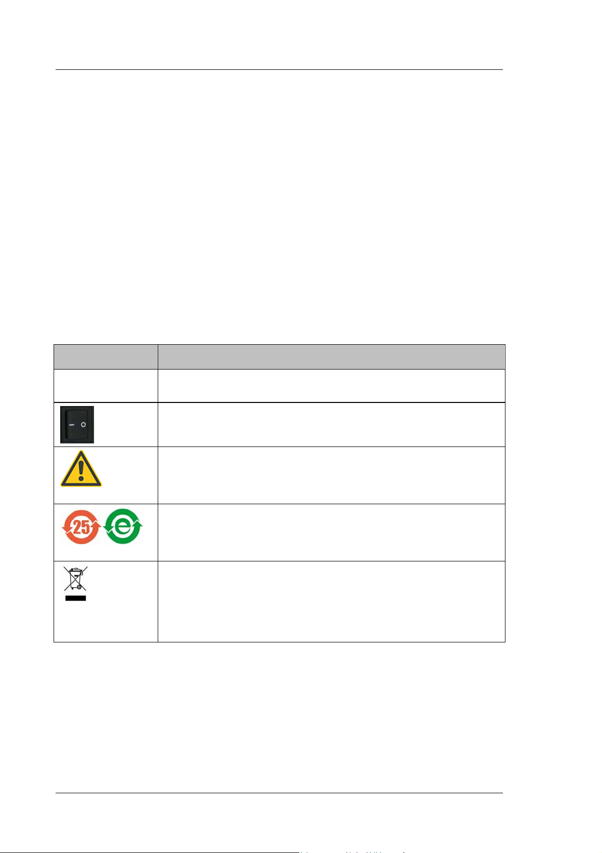
1.2.1 Symbols on the Pump and in the Manual
The table shows the symbols used on the pump:
Symbol Description
Alternating current—Courant alternatif
˜
Power supply is on (-)—L'instrument est mis sous tension (-) and
Power supply is off (O)—L'instrument est mis hors tension (O)
Refer to the Operating Instructions to prevent risk of harm to the operator and to
protect the instrument against damage.
Référez-vous à ce manuel pour éviter tout risque de blessure à l'opérateur et/ou
protéger l'instrument contre tout dommage.
Label according to the "Measures for Administration of the Pollution Control of
Electronic Information Products" (China RoHS) guideline
Étiquette "Measures for Administration of the Pollution Control of Electronic
Information Products" (China RoHS)
WEEE (Waste Electrical and Electronic Equipment) label—For more
information, see the WEEE Information section in the "Installation and
Qualification Documents for HPLC Systems" binder. Étiquette WEEE (Waste
Electrical and Electronic Equipment) —Pour plus d'informations, référez-vous au
chapitre WEEE Information dans le classeur "Installation and Qualification
Documents for HPLC Systems".
Page 2 Operating Instructions
Page 17
UltiMate 3000 Series:
SD, RS, and BM Pumps
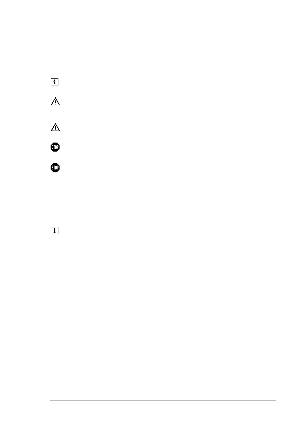
At various points throughout the manual, messages of particular importance are indicated
by certain symbols:
Tip: Indicates general information, as well as information intended to
optimize the performance of the instrument.
Important: Indicates that failure to take note of the accompanying information
could cause wrong results or may result in damage to the module.
Important: Indique que ne pas tenir compte de l'information jointe peut conduire
à de faux résultat ou endommager l'instrument.
Warning: Indicates that failure to take note of the accompanying information
may result in personal injury.
Avertissement: Indique que ne pas tenir compte de l'information jointe peut
entraîner des blessures corporelles.
1.2.2 General Safety Precautions
When working with analytical instrumentation, you should know the potential hazards of
using chemical solvents. Wear appropriate protective clothing.
Tips: Before initial operation of the pump, make sure that you are familiar with the
contents of this manual.
Observe any warning labels on the pump and see the related sections in these
Operating Instructions.
To avoid the possibility of personal injury and damage to the instrument, observe the
following general safety precautions when operating the pump or carrying out any
maintenance work:
Install the HPLC system in a well-ventilated laboratory. If the mobile phase includes
volatile or flammable solvents, do not allow them to enter the workspace.
For minimum interference effects, all components of the analytical system should be
connected to the same mains output (same phase).
The pump is primed with 2-propanol. During initial operation of the pump, make sure that
the solvents used are miscible with 2-propanol. Otherwise, follow the appropriate
intermediate steps.
When lifting or moving the pump, always lift by the sides of the instrument. Lifting the
pump by the front panel may damage the front panel door.
Operating Instructions Page 3
Page 18

UltiMate 3000 Series:
SD, RS, and BM Pumps
Do not place any heavy objects on the open front panel door. This may damage the door.
Always set a lower pressure limit for the HPLC pump. This prevents damage resulting
from leakage or from running the pump dry over a longer period. Activate liquid level
monitoring for the solvent reservoirs ( page 94).
To avoid that the pressure calibration of the pump is impaired, turn on the pump only
when the pump pressure is down. To ensure that the pressure is down, open the purge
valve before turning on the pump. If you are operating an ISO-3100BM, observe the
precautions on page 90.
Never run the pump dry. Damage to the pistons or the piston seals could result.
Before you start operating the pump, check the liquid level in the wash liquid reservoir
and refill the reservoir as needed. After turning on the pump, wait until the wash liquid
has passed all pump heads.
Always use fresh rear seal wash liquid.
Dionex advises against recycling the solvents. This may impair the performance of the
seals.
When connecting the capillaries, make sure that the connectors are free from
contaminants. Even minute particles may cause damage to the system, for example, to the
column.
After operation, rinse out buffers and solutions that form peroxides.
Before switching from buffer to organic solution, rinse the pump thoroughly with
deionized water.
When switching to another solvent, ensure that the new solvent is miscible with the one
contained in the pump. Otherwise, the pump can be damaged; for example, by
flocculation.
If the pump flow is interrupted for longer periods (> 1 hour), turn off the lamps in any UV
or RF detector connected to the pump. This will prevent evaporation in the flow cell.
If you want to connect an ESA Corona or Coulochem III detector to the pump, refer to
page 43 for details.
Always use the frits recommended by Dionex to prevent particulate matters from entering
the HPLC system. Using other frits may considerably affect the system performance.
Do not use stainless steel frits with the BM pumps; this renders the biocompatibility void.
Frits are used on the drawing side (in the solvent reservoirs) and on the high-pressure side
(in the inline filter).
If the mobile phase includes volatile or flammable solvents, avoid open flames and
sparks.
Page 4 Operating Instructions
Page 19

UltiMate 3000 Series:
SD, RS, and BM Pumps
If a leak occurs, turn off the pump and remedy the situation immediately.
Disconnect the pump from all power sources before removing the panels. When the
panels are removed, dangerous electrical connections will be exposed. The enclosure
should be opened only by authorized service personnel.
Always replace blown fuses with original spare part fuses from Dionex ( page 191).
Replace faulty power cords and communication cables.
Many organic solvents and buffers are toxic. Know the toxicological properties of all
mobile phases that you are using.
The toxicological properties of many samples may not be well known. If you have any
doubt about a sample, treat it as if it contains a potentially harmful substance.
Wear goggles when handling mobile phases or operating the pump. An eyewash facility
and a sink should be close to the unit. If any mobile phase splashes on the eyes or skin,
wash the affected area and seek medical attention.
Dispose of waste mobile phase in an environmentally safe manner that is consistent with
all local regulations. Do not allow flammable or toxic solvents to accumulate. Follow a
regulated, approved waste disposal program. Never dispose of flammable or toxic
solvents through the municipal sewage system.
Use only standard solvents (HPLC grade) and buffers that are compatible with all parts
that may be exposed to solvents.
In an UltiMate 3000 system, some components are made of PEEK™. While this polymer
has superb chemical resistance to most organic solvents, it tends to swell when in contact
with trichlormethane (CHCl3), dimethyl sulfoxide (DMSO), or tetrahydrofuran (THF). In
addition, it is attacked by concentrated acids, such as, sulfuric acid and nitric acid or a
mixture of hexane, ethyl acetate, and methanol. (Swelling or attack by concentrated acids
is not a problem with brief flushing procedures.)
Do not use PEEK tubing that is stressed, bent, or kinked.
Avoid looking directly into the pump light LED and do not use light focusing instruments
for viewing the light beam. The high luminosity of the lamp can be harmful to the eyes.
Before interrupting operation for several days or more or when preparing the pump for
transport, observe the precautions for shutting down the pump ( page 97).
Use original Dionex spare parts only. Substituting non-Dionex parts or using non-Dionex
accessories m
ay impair the performance of the instrument.
Do not use the pump in ways other than those described in these operating instructions.
Operating Instructions Page 5
Page 20

UltiMate 3000 Series:
SD, RS, and BM Pumps
1.2.3 Consignes Générales de Sécurité
Veuillez noter: Avant de commencer à utiliser la pompe, assurez-vous que vous
vous êtes familiarisés avec le contenu de ce manuel.
Observez des étiquettes d'avertissement sur l'appareil et référez-vous
aux sections correspondantes dans ce mode d'emploi.
Veuillez observer les consignes générales de sécurité suivantes lorsque vous utilisez
l'instrument ou que vous procédez à des opérations de maintenance.
Installez le système HPLC dans un laboratoire bien ventilé. Si la phase mobile contient
des solvants volatils ou inflammables, empêchez qu'ils ne pénètrent dans l'espace de
travail.
Afin d'éviter au maximum les interférences, tous les éléments du système analytique
doivent être raccordés à la même ligne secteur (même phase).
La pompe est stockée sous 2-propanol. Au cours démarrage de la pompe, assurez-vous
que les solvants utilisés soient miscibles avec le 2-propanol. Sinon, suivez les étapes
intermédiaires appropriées.
Le panneau avant bascule vers le haut. Afin d'éviter d'endommager la pompe lorsque que
vous la soulevez ou la déplacez, saisissez-la toujours par les côtés de l'unité.
Ne placez aucun objet lourd sur la porte ouverte du panneau avant. Ceci pourrait
endommager la porte.
Réglez toujours une limite de pression minimum pour la pompe HPLC. Ceci prévient les
dommages résultant de fuites ou de long-terme fonctionnement à sec de la pompe.
Activez la surveillance de niveau liquide pour des réservoirs ( page 94).
Afin d'éviter que le calibrage de pression de la pompe ne soit pas entravé, mettez en
marche la pompe seulement quand la pompe est sans pression. Toujours ouvrez la vis de
purge avant mettre la pompe en marche. Si la pompe est une ISO-3100BM, observez les
précautions figurant en page 90.
Ne faites jamais fonctionner la pompe à sec. Il peut en résulter des dommages aux pistons
ou aux joints de piston.
Avant de mettre en marche la pompe, assurez-vous que le réservoir de rinçage du joint
arrière est rempli. Attendez jusqu'à ce que le rinçage du joint arrière ait été pompé par
toutes les têtes de pompe.
Utilisez toujours le liquide frais pour le rinçage du joint arrière.
Dionex déconseille de recycler les solvants. Ceci peut nuire aux performances des joints.
Page 6 Operating Instructions
Page 21

UltiMate 3000 Series:
SD, RS, and BM Pumps
Lorsque vous connectez les capillaires, assurez-vous que les raccords sont exempts de
tout contaminant. Même d'infimes particules peuvent causer des dommages au système
(ex. diviseur de débit, vanne de régulation de débit et colonne).
Après utilisation, purgez le système des tampons et des susceptibles de former des
peroxydes.
Lorsque vous passez d’une solution saline à un solvant organique, effectuez un rinçage
intermédiaire de la pompe à l'eau dé-ionisée.
Lorsque vous passez à un autre solvant, assurez-vous que le nouveau solvant soit miscible
avec celui qui se trouve dans la pompe. Dans le cas contraire, la pompe peut être
endommagée; par exemple, par des floculations!
Si le débit de la pompe est interrompu pour des périodes prolongées (> 1 heure), éteignez
les lampes de tout détecteur UV ou RF raccordé à la pompe. Ceci empêchera
l'évaporation dans la cellule.
Si vous utilisez un détecteur ESA Corona ou Coulochem III avec la pompe, observez
les remarques figurant en page 43.
Si vous utilisez des phases mobiles avec une forte teneur en sel, ne faites pas fonctionner
la pompe sans rinçage du joint arrière pendant un temps prolongé (> 5 minutes). Ceci peut
endommager les joints de piston et le piston. Remplacer régulièrement le liquide dans le
réservoir du système de rinçage du joint arrière (au moins une fois par semaine).
Utilisez toujours les frittés recommandés par Dionex afin d'empêcher les particules
étrangères d'entrer dans le système HPLC. Utiliser d'autres frittés peut affecter
considérablement les performances du système.
N'employez pas des frittes d'acier inoxydable avec des versions biocompatible de la
pompe. Ceci rend vide de compatibilité biologique de la pompe.
Si la phase mobile contient des solvants volatils ou inflammables, évitez les flammes nues
et les sources d’étincelles à proximité.
Si une fuite survient, arrêtez l'instrument et résolvez le problème immédiatement.
Quand les capots de protection de l’appareil sont démontés, vous êtes exposés à des
connexions électriques sous haute tension deviennent accessibles. Débranchez la pompe
de toute source d'alimentation électrique avant de retirer les capots. Ne démontez les
capots de protection que si cela est explicitement demandé au cours de ces instructions.
Remplacez toujours les fusibles grillés par des fusibles de rechange d'origine Dionex
( page 191).
Remplacez les cordons d'alimentation électrique et les câbles de communication
défectueux.
Operating Instructions Page 7
Page 22

UltiMate 3000 Series:
SD, RS, and BM Pumps
De nombreux solvants organiques et solutions salines sont toxiques. Informez-vous des
propriétés toxicologiques de toutes les phases mobiles que vous utilisez. Portez le
vêtement de protection approprié.
Les propriétés toxicologiques de nombreux échantillons peuvent être mal connues. Au
moindre doute concernant un échantillon, traitez-le comme s'il contenait une substance
potentiellement dangereuse.
Portez des lunettes de protection lorsque vous manipulez des phases mobiles ou que vous
utilisez l'instrument. Une installation permettant de se laver les yeux ainsi qu'un lavabo
doivent se trouver à proximité du système. Si une phase mobile, quelle qu'elle soit, entre
en contact avec vos yeux ou votre peau, rincez abondamment la zone affectée à l’eau,
puis.
Débarrassez-vous de tous les déchets de phase mobile de manière écologique,
conformément à la règlementation en vigueur au niveau local. Empêchez impérativement
l'accumulation de solvants inflammables et/ou toxiques. Suivez un programme
d'élimination des déchets règlementé et approuvé. Ne jetez jamais de solvants
inflammables et/ou toxiques dans le système municipal d'évacuation des eaux usées.
Utilisez uniquement des solvants (qualité HPLC) et des solutions salines compatibles
avec les matériaux exposés phase mobiles.
Dans un système UltiMate 3000, certaines composantes sont en PEEK. Bien que ce
polymère présente une excellente résistance chimique à la plupart des solvants
organiques, il a tendance à gonfler lorsqu'il est en contact prolongé avec du chloroforme
(CHCl3), du diméthyle sulfoxyde (DMSO) ou du tétrahydrofurane (THF). De plus, il est
attaqué par des acides concentrés tels que l'acide sulfurique et l'acide nitrique ou d'un
composé du hexane, éthyle acétate et méthanol. (Ces acides peuvent cependant être
utilisés dans le cadre de procédures de nettoyage, à condition que l’exposition soit brève.)
N'utilisez pas de tubes PEEK écrasés, pliés ou abimés.
Ne regardez jamais directement la DEL pour l'éclairage intérieur dans la pompe et ne
regardez pas du faisceau lumineux par des instruments qui focalisent le rayon lumineux.
L'intensité lumineuse de la lampe peut être nocive pour les yeux.
Avant d'interrompre le fonctionnement pendant plusieurs jours ou plus, observez les
précautions figurant en page 97.
Utilisez des pièces de rechange d'origine Dionex. Effectuer des remplacements par des
pièces ne provenant pas de Dionex ou utiliser des accessoires ne provenant pas de Dionex
peut affecter les performances de l'instrument.
N'utilisez pas la pompe de manière autre que celles décrites dans ce manuel.
Page 8 Operating Instructions
Page 23

UltiMate 3000 Series:
SD, RS, and BM Pumps
1.3 Intended Use
The pump has been designed to perform equally well as a dependable system for routine
analyses and as a sophisticated research instrument for use in high-performance liquid
chromatography (HPLC) and ultra-high performance liquid chromatography (UHPLC)
applications, especially as part of the UltiMate 3000 system. However, the pump can also
be used with other HPLC systems if adequate control inputs and outputs are available. A
PC with USB port is required.
The pump is controlled by the Chromeleon Chromatography Management System. If you
want to operate the pump as part of the UltiMate 3000 system with other data systems, such as
Analyst® (AB Sciex), Compass™/ HyStar™ (Bruker Daltonics), or Xcalibur™ (Thermo
Scientific), contact the Dionex sales organization.
Please note that the pump may be operated only with Dionex accessories and spare parts
( page 191) and within its technical specifications ( page 187).
If there is any question regarding appropriate usage, contact Dionex before proceeding.
Dionex cannot be held liable for any damage, material or otherwise, resulting from
inappropriate or improper use of the pump.
1.4 Federal Communications Commission (FCC) Note
This equipment has been tested and found to comply with the limits for a Class A digital
device, pursuant to part 15 of the U.S. FCC Rules. These limits are designed to provide
reasonable protection against harmful interference when the equipment is operated in a
commercial environment. This equipment generates, uses, and can radiate radio frequency
energy and, if not installed and used in accordance with the instruction manual, may cause
harmful interference to radio communications. Operation of this equipment in a residential
area is likely to cause harmful interference, in which case the user will be required to
correct the interference at his expense.
Operating Instructions Page 9
Page 24

UltiMate 3000 Series:
SD, RS, and BM Pumps
Page 10 Operating Instructions
Page 25

UltiMate 3000 Series:
SD, RS, and BM Pumps
2 Overview
2.1 Unit Description
The pump is the heart of the Dionex UltiMate 3000 system. The pump performs equally
well as a flexible and reliable module for routine analysis and sophisticated research tasks
in HPLC and UHPLC and can be used in numerous laboratory environments:
The patented isokinetic pre-compression allows a precise and almost pulse-free flow.
The technical specification meets the highest requirements for flow rate reproducibility,
zero pulsation, and operational reliability ( page 187).
All pumps are fitted with floating pistons, allowing compensation for small mechanical
tolerances within the specification and thus enhancing the robustness of the pump.
As a standard, all pumps are equipped with an active rear seal wash system ( page 21).
Various monitoring and diagnostic features are provided for optimum system
performance and reliability ( page 26).
The pump is designed for easy access to the fluid components, allowing fast and reliable
maintenance while the instrument remains in the UltiMate 3000 system stack.
For the secure and functional positioning of the solvent reservoirs on top of the pump, the
Solvent Racks of the UltiMate 3000 series are available from Dionex ( page 13).
Except for the SR-3000, all Solvent Racks include an integrated vacuum degasser.
The pump can be fully controlled by the Chromeleon Chromatography Management
System, providing a high degree of system integration.
All parts that may be exposed to solvents are made of materials that provide optimum
resistance to the most commonly used solvents and buffer solutions.
Operating Instructions Page 11
Page 26
UltiMate 3000 Series:
SD, RS, and BM Pumps
2.2 Pump Configurations
2.2.1 Overview
The pump is available in the following configurations:
Pump Description Part No.
ISO-3100SD Isocratic pump (analytical, 1 solvent)
working pressure: up to 62 MPa (9000 psi)
ISO-3100BM Same as ISO-3100SD, however as
biocompatible micro pump with pulse damper ( page 24)
worki
ng pressure: up to 41 MPa (6000 psi)
LPG-3400SD Low-pressure gradient pump (analytical, 4 solvents)
with integrated vacuum degasser
working pressure: up to 62 MPa (9000 psi)
LPG-3400RS Same as LPG-3400SD, however,
working pressure: up to 103 MPa (15000 psi)
LPG-3400BM Same as LPG-3400SD,
however, as biocompatible micro pump
working pressure: up to 50 MPa (7250 psi)
DGP-3600SD Dual low-pressure gradient pump (analytical)
Two separate pumps in one enclosure (2 x 3 solvents),
working pressure: up to 62 MPa (9000 psi)
DGP-3600RS Same as DGP-3600SD, however,
working pressure: up to 103 MPa (15000 psi)
5040.0011
5042.0011
5040.0031
5040.0036
5042.0036
5040.0061
5040.0066
DGP-3600BM Same as DGP-3600SD,
however, as biocompatible micro pump
working pressure: up to 50 MPa (7250 psi)
HPG-3200SD High-pressure gradient pump (analytical; 2 solvents)
working pressure: up to 62 MPa (9000 psi)
HPG-3200RS Same as HPG-3200SD, however,
working pressure: up to 103 MPa (15000 psi)
HPG-3400SD High-pressure gradient pump (analytical) with
solvent selector (2 from 4)
working pressure: up to 62 MPa (9000 psi)
HPG-3400RS Same as HPG-3400SD, however,
working pressure: up to 103 MPa (15000 psi)
5042.0066
5040.0021
5040.0026
5040.0041
5040.0046
Page 12 Operating Instructions
Page 27

UltiMate 3000 Series:
SD, RS, and BM Pumps
The isocratic pumps and the micro pumps have an inline filter installed. All other pumps
are shipped with a two-step mixing system, including a capillary mixer and a static mixer.
For more information, see page 22.
2.2.2 Combinations of UltiMate 3000 Pumps and Solvent Racks
The Solvent Racks of the UltiMate 3000 system series are an ideal complement to the
pumps of the UltiMate 3000 pump series, whether you need high efficiency degassing of
the solvents or simply want to safely organize your solvent reservoirs.
Solvent Rack Part No.
SRD-3200 Solvent Rack with analytical 2-channel vacuum degasser
typically for use with the following pumps:
- one HPG-3200
- one ISO-3100SD
SRD-3400 Solvent Rack with analytical 4-channel vacuum degasser
typically for use with the following pumps:
- one HPG-3400
- two HPG-3200s in a two-stack system
- one HPG-3200 or ISO-3100SD if you want to degas the solvents and the wash
liquid of an UltiMate 3000 series autosampler
SRD-3600 Solvent Rack with analytical 6-channel vacuum degasser
typically for use with the following pumps:
- one DGP-3600
- two HPG-3200s in a two-stack system
- one HPG-3200 and one HPG-3400 in a two-stack system
- one HPG-3400 if you want to degas the solvents and the wash liquid of an
UltiMate 3000 series autosampler
SR-3000 Solvent Rack without vacuum degasser
typically for use with an LPG-3400 or ISO-3100BM
5035.9250
5035.9245
5035.9230
5035.9200
For information about online degassing of the wash liquid, see the Autosampler Manual.
Operating Instructions Page 13
Page 28

UltiMate 3000 Series:
SD, RS, and BM Pumps
2.2.3 Special Information for Biocompatible Pumps
The UltiMate 3000 pump series includes the following biocompatible pump types:
LPG-3400BM
DGP-3600BM
ISO-3100BM
Except for the fluid components, the BM pumps are identical to the SD and RS pumps.
Therefore, almost all descriptions in this manual apply also to the BM pumps. If some detail
applies to only one pump type, the type will be identified by name. The differences are as
follows:
The fluid components are made of titanium. Titanium is a base material, similar to aluminum
and magnesium. When titanium is processed, a titanium oxide film builds up on the
component surface, ensuring excellent corrosion resistance. The color of titanium and stainless
steel is slightly different. In addition, titanium parts are lighter than parts made of stainless
steel. Nevertheless, you can easily confuse titanium with stainless steel parts.
Observe the following:
When substituting parts be sure to install the appropriate replacement part for the BM
pumps. For information about the part numbers and for installation details, see the related
service sections ( page 123 and following pages) and the Consumables and Spare Parts
section ( page 199).
When connecting the solvent reservoirs, make sure to use appropriate filter frits on the
end of the solvent lines (shipped with the pump). As a standard, filter holders with
stainless steel frits are provided in the accessories kit of the SRD-3x00 Solvent Racks of
the UltiMate 3000 system. Replace the stainless steel frits with the frits from the
accessories kit of the pump ( page 48).
Ring seals with a titanium
spring are installed as piston seals in the biocompatible pumps,
whereas common ring seals with a steel spring are used in the SD and RS pumps.
Therefore, do not confuse these seals.
Page 14 Operating Instructions
Page 29

UltiMate 3000 Series:
SD, RS, and BM Pumps
2.3 Operating Principle
The pump is a zero-pulsation, serial dual-piston pump with electronic compressibility
compensation. The pump head includes two cylinders—working cylinder and equilibration
cylinder—that are connected in series. The solvent passes both cylinders successively.
Continuous delivery is achieved as follows: The working cylinder delivers at the
appropriate flow rate while simultaneously filling the serially connected equilibration
cylinder. The latter serves as a reservoir and delivers while the working cylinder carries
out the suction stroke.
The characteristic feature of the patented isokinetic pre-compression is the overlapping phase
of the delivery strokes of the working and equilibration cylinders. When delivering
compressible liquids without controlled pre-compression, the pulsation increases as the
working pressure increases, since part of the delivery stroke is required for compressing the
solvent in the working cylinder. Pulsation during the pre-compression phase is reduced to a
minimum by velocity modulation of the drive. The highly constant delivery is ensured by a
patented secondary control system (automatic compressibility compensation). The flow rate is
always kept constant in relation to the atmospheric pressure.
The schematics in section 8 illustrate how the pumps operate ( page 161).
Operating Instructions Page 15
Page 30
UltiMate 3000 Series:
SD, RS, and BM Pumps
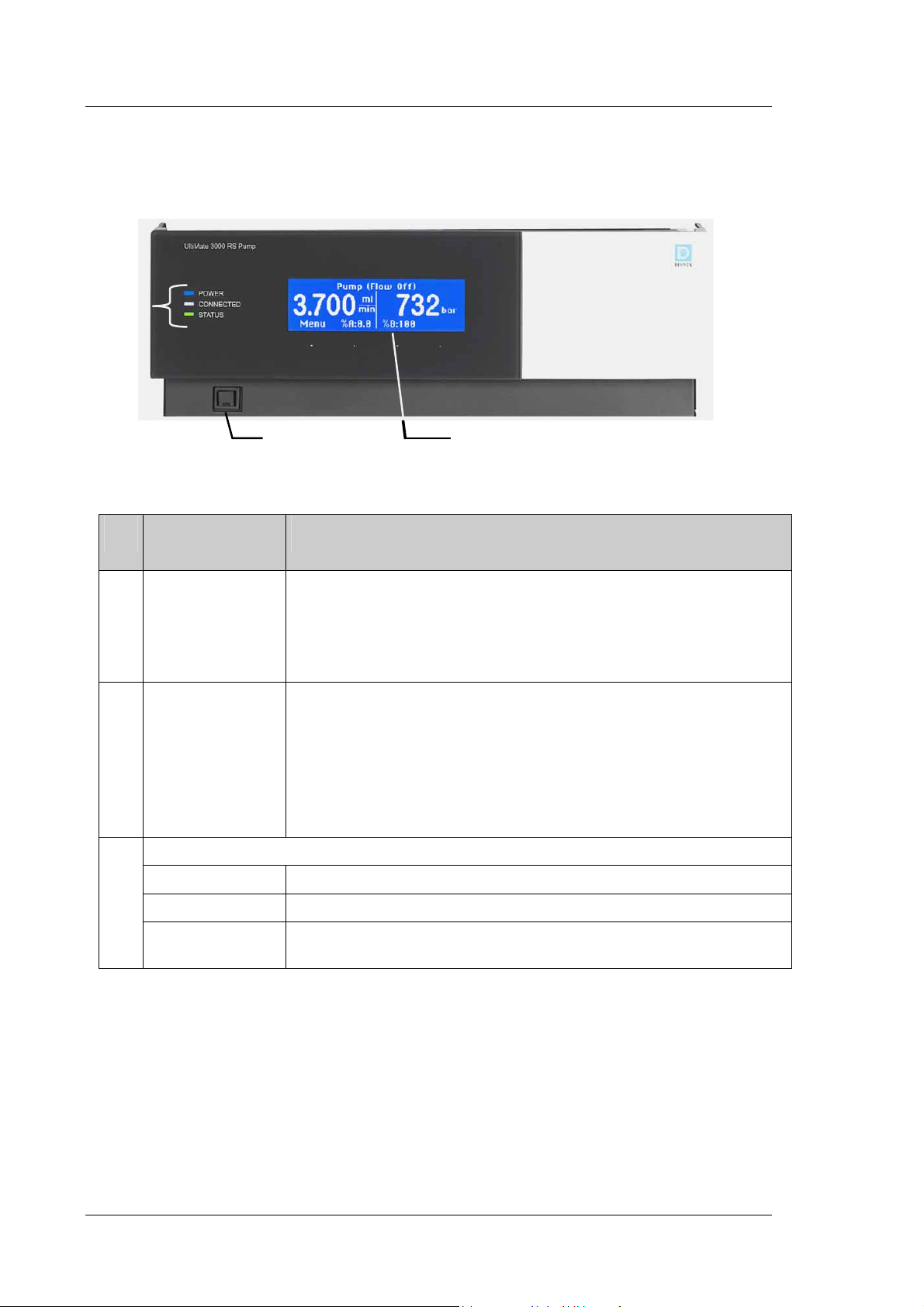
2.4 Front Panel Elements
3
2
1
Fig. 1 Front panel view
No. Front Panel
Element
1 Display Shows information about the pump, for example:
2 Standby button Switches the pump to Standby mode (the LED is red).
3
LEDs
Power The LED is blue when the pump is turned on.
Connected The LED is green when the pump is connected in Chromeleon.
Status The LED is green when the pump is ready for operation.
Description
- General information upon power up ( page 61)
-
Status screen ( page 62)
-
Functions and menus ( pages 70 and 72)
- Messages
To cancel Standby mode and resume operation, press the Standby button
again (the LED is not lighted).
Notes:
To allow the pump to change the mode, press and hold the Standby button for
at least 1 second. If you switch a pump to which an SRD-3x00 Solvent Rack
is connected to the Standby mode, the Solvent Rack, too, will be set to
Standby mode.
The LED is red when an error has been detected, for example, a leak.
( page 105)
Page 16 Operating Instructions
Page 31

2.5 Rear Panel
UltiMate 3000 Series:
SD, RS, and BM Pumps
3 1 4 5 6 7 2
Fig. 2: Rear panel view
No. Description
1
2
3
4
5
6 USB hub (3 USB ports, USB 2.0 or 1.1)
7 USB port (USB 2.0 or 1.1) for connecting the pump to the Chromeleon computer
Power switch ( page 18)
Fuse cartridge ( page 18)
Main power receptacle ( page 31)
Digital I/O ports for communication with external devices ( page 19)
Solvent Rack port for connection of an SRD-3x00 Solvent Rack ( page 19)
Depending on the UltiMate 3000 system configuration, for connection of one UltiMate 3000
system module each or for connection of one USB hub each ( page 18).
( page 18)
Operating Instructions Page 17
Page 32

UltiMate 3000 Series:
SD, RS, and BM Pumps
2.5.1 Power Switch
The power switch on the rear panel is the main power switch for the pump. Turn on the
power switch before initial operation of the pump and leave it on. For routine operation,
leave the main power switch on. For routine on/off control, use the standby button on the
front of the pump ( page 16). Press and hold the button for one second to allow the pump
to change the mode. Turn off the main power switch when instructed to do so, for example,
before performing a service procedure or when interrupting operation for longer periods
(one week or more). In this case, also observe the precautions on page 97.
2.5.2 Fuse Cartridge
The fuse cartridge contains two slow-blow fuses rated at 2 A, 250 V. For inform
ation
about how to change the fuses, see page 158.
2.5.3 USB Connector
The Chrom
eleon Chromatography Management System can use a USB connection to
control the pump. Data is transferred digitally by the appropriate USB cable ( page 30).
To ensure trouble-free operation, use only the cables shipped with the pump.
You can use the internal USB hub ( Fig. 2, no. 10) to connect three other instruments in the
UltiMate 3000 product line, depending on the configuration of the UltiMate 3000 system, or
three external USB hubs to the pump.
Important: Use these USB ports only for connections to Dionex instruments.
Dionex cannot guarantee correct functioning if instruments from other
manufacturers are connected.
Important: Dionex recommande d'utiliser les ports USB uniquement pour les
raccordements aux instruments Dionex. Dionex ne peut garantir le bon
fonctionnement si les instruments d'autres fabricants sont raccordés.
For information about how to connect the pump to the Chromeleon computer, see
sections 3.4.1 and 3.4.2 ( page 30).
Page 18 Operating Instructions
Page 33

UltiMate 3000 Series:
SD, RS, and BM Pumps
2.5.4 Digital I/O
The digital I/O ports provide two inputs and two relay outputs that can be used to exchange
digital signals with external devices. To connect external devices to the digital I/O ports,
use the appropriate mini-DIN cables (part no. 6000.1004). For more information, see
page 31.
For information about the functions of the connector pins and pin assignment, see page 215.
Tip: If you want to connect an ESA Corona or Coulochem III detector to the pump,
refer to page 43 for details.
2.5.5 Solvent Rack
Use this port to connect an SRD-3x00 Solvent Rack with integrated vacuum degasser to
the pump.
Important: Do not substitute any other Solvent Rack for the Solvent Racks
mentioned in the table on page 13.
Important: Ne remplacez les dégazeurs de la série SRD-3x00 mentionnés sur la
page 13 par aucun autre type de dégazeur.
For information about the pin assignment of the Solvent Rack port, see page 216. For
information about how to install and operate the Solvent Rack, see the Operating
Instructions for the instrument.
Operating Instructions Page 19
Page 34

UltiMate 3000 Series:
SD, RS, and BM Pumps
2.6 Fluid Connections
The front panel door tilts upward to provide easy access to the fluid connections in the
pump. Tilt the front cover upward. The open front panel locks in the topmost position.
Important: The open front panel door is not designed to carry weight. Therefore,
you should not place any objects on the open door.
When lifting or moving the pump, always lift by the sides of the
instrument. Lifting the pump by the front panel may damage the
front panel door.
Important: Ne placez aucun objet lourd sur la porte ouverte du panneau avant.
Ceci peut endommager la porte.
Lorsque vous soulevez ou déplacez la pompe, saisissez-la toujours
par les côtés de l'instrument. Soulever la pompe par le panneau avant
risque d'endommager la porte du panneau avant.
Capillary guides on the pump bottom facilitate routing the capillaries to devices that are
located below the pump in the UltiMate 3000 system stack.
Capillary guide
Fig. 3: Capillary guides on the pump bottom
See section 8 for the interior components and flow schematics of the pumps.
For the … Find the … On page
ISO-3100SD Interior components
Liquid flow path
ISO-3100BM Interior components
Liquid flow path
LPG-3400 Interior components
Liquid flow path
162
163
165
166
168
169
DGP-3600 Interior components
Liquid flow path
HPG-3200 Interior components
Liquid flow path
HPG-3400 Interior components
Liquid flow path
172
173
176
177
179
180
Page 20 Operating Instructions
Page 35

UltiMate 3000 Series:
SD, RS, and BM Pumps
2.7 Rear Seal Wash System
As a standard, the pump is equipped with an active rear seal wash system. Rear seal
washing helps avoiding damages to the pistons, piston seals, and support rings, and thus
increases the piston life. The rear seal wash system consists of a peristaltic pump and a
detector. The seal washing liquid passes the individual components as shown in Fig. 4.
Fig. 4: Rear seal wash system (here for a pump with two pump heads)
(The arrows indicate the flow path of the wash liquid through the pump.)
No. Description No. Description
1 Liquid reservoir of the rear seal wash system 4 + 5 Pump head
2
Peristaltic pump ( page 50)
3
Peristaltic tubing (Pharmed
®
) ( page 50)
6 Det
7 To waste
ector
For information about how to connect the rear seal wash system, see page 50. For more
information about how to operate the pumps with rear seal washing, see section 5.5.6
( page 83).
Operating Instructions Page 21
Page 36

UltiMate 3000 Series:
SD, RS, and BM Pumps
2.8 Mixing System and Inline-Filter
RS and SD pumps except ISO-3100SD
All RS and SD pumps (except ISO-3100SD) are shipped with a two-step mixing system
(SpinFlow). The system includes a capillary mixer and a static mixer. DGP-3600 pumps have
to separate two-step mixing systems.
Pump Two-step mixing system
All pumps except for
HPG-3x00RS
HPG-3x00RS Mixing volume: 200 µL; including:
Mixing volume: 400 µL; including:
Capillary mixer (volume: 50µL)
Static mixer (volume: 350 µL)
Capillary mixer (volume: 50µL)
Static mixer (volume: 150 µL)
In the capillary mixer, the solvent streams delivered by the pump are combined and
premixed before they enter the static mixer. The static mixer improves the mixing quality
of the combined solvent streams and thus guarantees a smoother baseline.
Static mixer
Capillary mixer
Fig. 5: Two-step mixing system (here in an HPG-3400SD)
In addition, mixing systems with other volumes are available for these pumps. For more
information, see Optimizing the Pump for Specific Applications ( page 183).
ISO-3100SD and BM pumps
These pum
ps do not have a mixing system, but have an inline filter instead ( page 149).
Page 22 Operating Instructions
Page 37

UltiMate 3000 Series:
SD, RS, and BM Pumps
2.9 Purge Unit
The purge unit comprises a pressure transducer for the system pressure and purge valve
with purge valve knob and outlet nozzle.
Connection port for
the right pump head
(if available)
Purge outlet nozzle
Fig. 6: Purge unit
Connection port
for the left pump head
Pressure transducer
for
Purge valve knob
Connection port (capillary mixer/
inline filter/pulse damper)
Only HPG-3x00
In addition, the purge unit combines the eluent streams from the pump heads.
Tip: You may open the purge valve (by turning the valve knob counterclockwise) to
reduce the system pressure. However, if you are operating an ISO-3100BM,
observe the precautions on page 90.
2.10 Leak Sensor
A leak sensor is installed inside the pump. If liquid collects in the drip tray under the fluid
connections, the leak sensor reports a leak. The Status LED on the front panel door
changes to red, a beep sounds, and a message appears on the pump display and in the
Chromeleon Audit Trail.
When the leak sensor reports a leak, eliminate the cause for the leakage and dry the leak
sensor ( page 124).
Leak detection is enabled as a standard when the pum
p is shipped. For more information, see
section 5.5.8 ( page 86).
Operating Instructions Page 23
Page 38

UltiMate 3000 Series:
SD, RS, and BM Pumps
2.11 Vacuum Degasser
Usually, a vacuum degasser is used to remove gas bubbles trapped in the solvents. LPG3400 pumps have an inbuilt vacuum degasser. For all other pumps, consider connecting an
appropriate SRD-3x00 Solvent Rack ( page 13) or another external vacuum degasser.
Observe the general precaution for degasser operation ( page 88).
Tip: Normal phase eluents usually show only a low concentration of dissolved
gases. Therefore, it is normally not required to use a degasser with these
eluents
If the UltiMate 3000 system includes an UltiMate 3000 series autosampler, you should
degas also the wash liquid on a continuous basis. The procedure how to prepare and install
the wash liquid lines is similar to the steps for the solvent supply ( page 49). For more
information, see the Autosampler Manual.
2.12 Pulse Damper
ISO-3100BM pumps have an integrated pulse damper that reduces the already low
pulsation of the pump even further ( Technical Information, page 187).
The pulse damper consists of a reservoir, filled with isopropanol, and a membrane that is
placed in the mobile phase line. The damper diminishes pressure pulsations that would
otherwise interfere, for example, with sensitive electrochemical detection.
Thus, an ISO-3100BM is the ideal choice for electrochemical detection applications, but also
for applications for which lowest pulsation is one of the main requirements.
When operating an ISO-3100BM, also observe the general operating precautions on page 90.
Page 24 Operating Instructions
Page 39

UltiMate 3000 Series:
SD, RS, and BM Pumps
2.13 Chromeleon Software
The pump can be controlled by the Chromeleon Chromatography Management System. To
control the pump, an appropriate Chromeleon version and license are required.
Two modes of software control are available:
Direct Control
With direct control, you select operating parameters and commands in the Commands
(F8) dialog box. Direct commands are executed as soon as they are entered. For routine
operation, most parameters and commands are available also on a control panel. For more
information about direct control, see page 65.
Automated Control
With automated control, you create a program (or PGM File). This is a list of control
commands, executed in chronological order, for automated operation of the pump.
Programs can be created automatically with the help of a software wizard or manually by
editing an existing program. For more information about automatic control, see page 68.
Tip: All software details in this manual refer to Chromeleon 6.80.
If you want to operate the pump with Chromeleon 7, refer to the following
documents for information about how to perform the related processes in
Chromeleon 7 (all documents are included in the Chromeleon 7 shipment):
Chromeleon 7 Help—provides extensive information and comprehensive
reference material for all aspects of the software.
Quick Start Guide—describes the main elements of the user interface and
guides you step-by-step through the most important workflows.
Reference Card—provides a concise overview of the most important
workflows.
Installation Guide—provides basic information about module installation
and configuration. For specific information about a certain module, refer
to the Chromeleon 7 Help.
Please also note the following:
Chromeleon 7 terminology is different from the terminology used in
Chromeleon 6.80. For details, refer to the 'Glossary - Chromeleon 7,'
which is available in the Documents folder of your Chromeleon 7
installation.
Chromeleon 7 may not yet support all functions supported in
Chromeleon 6.80.
Operating Instructions Page 25
Page 40

UltiMate 3000 Series:
SD, RS, and BM Pumps
2.14 Wellness, Predictive Performance and Diagnostics
System Wellness monitors the health of the pump. Therefore, the pump supports several
performance and reliability features that can help you detect small problems before they
turn into big ones:
Internal monitoring of all mechanical operations
Automatic self test upon power up
Leak sensor ( page 23)
Active rear seal wash system ( page 21)
When an error is detected, the Status LED on the front panel door is red, a beep sounds, and a
message appears on the pump display ( page 105).
When the pump is operated with Chromeleon, additional functions for estimating the lifetime
of consumables and monitoring and recording service and (re)qualification information
(= predictive performance; page 91) are available. To check the performance of certain
pump components and the overall performance of the instrument, Chromeleon also supports
diagnostics functions for the pump ( page 93).
Page 26 Operating Instructions
Page 41

UltiMate 3000 Series:
SD, RS, and BM Pumps
3 Installation
3.1 Facility Requirements
Make sure that the installation site meets the power and environmental specifications
listed in the Technical Information section ( page 187).
Install the pump in the laboratory on a stable surface. Make sure that the position is
horizontal and free of vibrations.
Make sure that the surface is resistant to solvents.
Avoid locations with extreme changes in temperature. Also, avoid locations with extreme
direct sunlight and high humidity.
Allow sufficient clearance behind and to the sides of the pump for power connections and
ventilation.
3.2 Unpacking
All electrical and mechanical components of the pump are carefully tested before the
instrument is shipped from the factory. After unpacking, please inspect the instrument for
any signs of mechanical damage, which might have occurred during transit.
Tips: Immediately report any shipping damage to both, the incoming carrier and
Dionex. Shipping insurance will compensate for the damage only if reported
immediately
Keep the original shipping container and packing material. They provide
excellent protection for the pump in case of future transit. Shipping the pump
in any other packaging automatically voids the product warranty.
1. Place the shipping container on the floor and remove the accessories kit, drain kit, and
power cord.
2. Grasp the pump by the sides. Slowly and carefully, pull the instrument out of the
shipping container and place it on a stable surface
Important: To prevent the pump from falling, grasp the pump by the sides, and
then lift the pump together with the foam spacers out of the shipping
container. Do not lift the pump by the foam spacers or the front
panel.
Important: Afin d'empêcher la pompe de tomber, saisissez-la par les côtés. Ne
soulevez la pompe à l’aide du matériau d'emballage ou par la porte
du panneau avant.
Operating Instructions Page 27
Page 42

UltiMate 3000 Series:
r
p
r
SD, RS, and BM Pumps
3. Remove the foam spacers, and then remove the polythene packaging.
4. Tilt the front panel upward and remove the foam inserts securing the front panel door
during shipment.
5. Before connecting the pump to the power source, wait approximately 4 hours to allow
the instrument to come to room temperature and to allow any condensation that might
have occurred during shipping to evaporate. After 4 hours, check the pump; if
condensation still exists, allow the pump to continue to warm up (without connecting
it to the power source) until the condensation is completely gone.
3.3 Positioning the Pump in the UltiMate 3000 System
If the pump is part of an UltiMate 3000 system, for example, for analytical HPLC
applications, you should stack the individual modules, for example, as shown in Fig. 7 and
interconnecting them on the rear panel as shown in Fig. 8.
However, the arrangem
ent of the system modules depends on the application.
Solvent Rack
Pum
Autosample
Column Compartment
Detecto
Fig. 7: Module arrangement for an UltiMate 3000 system (example)
Page 28 Operating Instructions
Page 43

UltiMate 3000 Series:
p
t
SD, RS, and BM Pumps
Solvent Rack
Optional
ESA Detector
(Corona or Coulochem III)
Pump
Autosampler
Column Com
Detector
(here DAD-3000/
MWD-3000)
artmen
Fig. 8: Example for the rear panel connections on an UltiMate 3000 system
Apart from the Solvent Rack, all modules of the UltiMate 3000 system can be connected
separately to the Chromeleon computer by using the USB port on the rear panel of the
instrument. However, Dionex recommends interconnecting all modules, and then
connecting the system to the Chromeleon computer with only one connection. For systems
with a DAD-3000(RS) or MWD-3000(RS), you can use only the hub on the detector for
the connection. For systems with a VWD-3x00(RS), use only the hub on the pump.
Operating Instructions Page 29
Page 44

UltiMate 3000 Series:
SD, RS, and BM Pumps
3.4 Connecting the Pump
3.4.1 General Information
If you want to operate the pump with Chromeleon
Verify that Chromeleon is installed on the computer and that the license code is entered before
you connect the pump to the USB port on the Chromeleon computer and turn on the pump
power. Only if you install Chromeleon first, the USB driver for the pump is automatically
loaded and the Windows® operating system can detect the pump when the power is turned on.
3.4.2 Connecting the USB Cable
Connect the pump to the Chromeleon computer via the USB ports on the rear panel
( Fig. 2, page 17). Select one of the following alternatives:
Connect the pump directly to the USB port on the computer.
Connect the pump to an internal USB port on another module in the UltiMate 3000
system that is connected to the computer ( page 29).
Connect the pump to the computer by using an external USB hub if necessary. (However,
this may be the source for communication problems, depending on the quality of the hub.)
The following cables are available (both cables are provided in the accessories kit of the
pump):
USB Cable Part No.
USB cable, type A to type B, high speed USB 2.0 (cable length: 5 m) 6911.0002
USB cable, type A to type B, high speed USB 2.0 (cable length: 1 m) 6035.9035
Tip: The USB standard limits the USB cable length to 5 meters. Each USB device
can be separated from the PC or next USB hub by no more than 5 meters
Page 30 Operating Instructions
Page 45

UltiMate 3000 Series:
SD, RS, and BM Pumps
3.4.3 Connecting the Power Cord
Use the power cord shipped with the pump to connect the instrument to the main power
source. Connect the power cord from the main power receptacle on the rear panel
( Fig. 2, page 17) to a grounded power source. No manual adjustment is required to
adapt the line voltage to local voltage requirements.
For minimum interference effects, all components of the UltiMate 3000 system and the
Chromeleon computer should be connected to the same mains output (same phase).
3.4.4 Connecting the Solvent Rack and Digital I/O
Solvent Rack
If the UltiMate 3000 system includes an SRD-3x00 Solvent Rack, connect the solvent rack
port on the rear panel of the pump to the related port on the rear panel of the Solvent Rack.
The appropriate connection cable is included in the accessories pack of the Solvent Rack.
Digital I/O
To connect devices to the digital I/O ports on the rear panel of the pump, use a 6-pin mini-DIN
signal cable. The cable is available from Dionex (part no. 6000.1004).
1. Plug the 6-pin connector of the mini-DIN cable into the Digital I/O port 1 (or 2). For
information about the functions of the connector pins and pin assignment, see
page 215.
2. For each relay output or digital input to be used, connect the appropriate signal wire
and ground wire to the corresponding connectors on the external device
( documentation provided with the external device).
3. When setting up the pump in the Chromeleon Server Configuration program
( page 35), select the corresponding relay outputs on the Relays page and the digital
inputs on the Inputs page.
Tip: If you want to connect an ESA Corona or Coulochem III detector to the pump,
refer to page 43 for details.
Operating Instructions Page 31
Page 46

UltiMate 3000 Series:
SD, RS, and BM Pumps
3.5 Setting Up the Pump in Chromeleon
This section provides brief instructions for setting up the pump in Chromeleon. For details,
see the Chromeleon Help.
Tip: When the pump is connected to the Chromeleon computer, verify that the
Chromeleon software is installed before turning on the pump power for the
first time. Only then, the Windows® operating system will detect the pump
automatically when the pump power is turned on.
3.5.1 Loading the USB Driver for the Pump
1. Turn on the computer power, if it is not already on.
2. Under the Windows® operating system (Vista™, XP, 7, or Server 2008), log on as a
local administrator if the computer is a local computer.
user with local computer administrator privileges if the computer is a network
computer.
3. Open the Chromeleon Server Monitor program by double-clicking the Chromeleon
Server Monitor icon on the Windows taskbar.
If the Server Monitor icon is not on the taskbar, click Start on the taskbar, point to
Programs (or All Programs, depending on the operating system), point to Chromeleon,
and then click Server Monitor.
4. Click Start to start the server.
5. Click Close to close the Server Monitor window. The Server Monitor icon
appears
on the taskbar.
Tip: Clicking the Quit Monitor button quits (exits) the Server Monitor
program, but does not stop the server. To stop the server, click Stop.
6. Turn on the main power switch on the rear panel of the pump.
7. Depends on the operating system
Windows® Vista™, Windows® 7, and Windows® Server 2008
will automatically detect the new pump and perform the USB installation. If Windows
fails to detect the pump and launches a wizard instead, this indicates that you connected
the pump to the computer and turned on the power for the first time before you installed
Chromeleon.
Page 32 Operating Instructions
Page 47

UltiMate 3000 Series:
SD, RS, and BM Pumps
To resolve the problem:
a) Click Cancel to exit the wizard.
b) Turn off the pump.
c) Install Chromeleon.
d) Turn on the power to the pump. Windows will now detect the pump and install the
USB software for the pump automatically.
Windows® XP
will automatically detect the new pump and launch the Found New Hardware Wizard,
which guides you through the USB installation. Select the following options:
a) If asked whether Windows can connect to Windows Update to search for software,
select No, not this time.
b) Accept the default option (Install the software automatically) and click Next>.
c) Click Finish when the wizard reports that the software for the pump has been installed.
If Windows fails to detect the pump and a message box asks for a USB configuration
file (cmwdmusb.inf), this indicates that you connected the pump to the computer and
turned on the power for the first time before you installed Chromeleon. To resolve the
problem:
a) Click Cancel in the Windows message box.
b) Turn off the pump.
c) Install Chromeleon.
d) Turn on the power to the pump. Windows will now automatically detect the pump and
launch the Found New Hardware Wizard.
Operating Instructions Page 33
Page 48

UltiMate 3000 Series:
SD, RS, and BM Pumps
3.5.2 Installing the Pump
After the USB software for the pump has been installed ( page 32), install and configure
the pump in Chromeleon:
1. Start the Chromeleon Server Monitor and the Chromeleon server if they are not yet
running ( page 32).
2. Start the Chromeleon Server Configuration program by clicking Start on the taskbar.
Point to Programs (or All Programs, depending on the operating system), point to
Chromeleon, and then click Server Configuration.
3. If necessary, click the plus sign next to the server name to display the items
underneath.
4. Select the timebase to which the pump will be assigned, or create a new timebase (on
the Edit menu, click Add Timebase).
5. Open the Add device to timebase dialog box. To do so, click Add Device on the Edit
menu or right-click the timebase and click Add Device on the menu.
6. On the Manufacturers list, click Dionex HPLC: UltiMate 3000 and on the Devices
list, click the pump you want to add, for example, HPG-3x00RS Pump or LPG-
3400SD Pump.
7. The configuration pages for the pump are opened. On each configuration page, verify
that the settings are correct and select additional settings if needed. For a description
of the pages, see section 3.5.3.1 ( page 35).
8. On the File menu, click Save Installation and then close the Server Configuration
program.
Page 34 Operating Instructions
Page 49

UltiMate 3000 Series:
SD, RS, and BM Pumps
3.5.3 Configuring the Pump
3.5.3.1 Initial Installation
On each configuration page for the pump, check and change the settings if necessary and
select additional settings if needed. You may reopen the configuration pages later again to
change the settings ( page 42).
Tip: Changing the settings for a specific application in the Commands dialog box,
in a program file (PGM), or on a control panel will not change the default
settings on the configuration pages.
For additional information about a page, click Help.
General Page
Display general information about the pump:
Fig. 9: General page
Device Type
Indicates the pump model.
Enable Virtual Mode
This check box should be cleared because Chromeleon only simulates the functions of the
pump when the virtual mode is active. If the Virtual Mode is enabled, the Module
Address box will be unavailable.
Operating Instructions Page 35
Page 50

UltiMate 3000 Series:
SD, RS, and BM Pumps
Module Address
Select the module address of the pump if necessary. Click Browse and then double-click
the pump that you want to use on the Device List. The address is automatically entered in
the Module Address box. (The button appears dimmed if the virtual mode is enabled.)
Download
Click the Download button to transfer the firmware version available for the pump in
Chromeleon to the pump. (The button appears dimmed if the virtual mode is enabled.)
The pump is shipped with the most recent firmware version. If a firmware update is ever
required, follow the steps in section 7.12 ( page 159).
Devices Page
The pump type determines the settings and options on this page.
Fig. 10: Devices page (here for a DGP-3600RS)
Main Device
Name (default name: PumpModule)
Displays the name used to identify the pump in the installation environment and in the
Chromeleon client. To control the pump with the existing control panels, accept the
default name. If you enter a different name, you may have to re-link the controls on the
control panels and edit the name in the program files.
Page 36 Operating Instructions
Page 51

UltiMate 3000 Series:
SD, RS, and BM Pumps
Under PumpModule, the following commands and properties are displayed, for
example, in the Commands dialog box ( page 65):
General pump properties and commands, such as, Connect, Connected,
Disconnected, and Degasser.
Specific groups of pump properties and commands, such as Pump or PumpLeft
and PumpRight (see table further down in this section), with the flow-related
properties and commands.
Degasser Control
Indicates whether the vacuum degasser in an LPG-3400 or in an SRD-3x00 Solvent
Rack can be operated and monitored. If it can, the related commands and properties
are available, for example, in the Commands dialog box.
Click Internal if the pump is an LPG-3400.
Click External if an SRD-3x00 Solvent Rack is connected to the pump.
In all other cases, click None.
Depending on the pump type
Pump Device or Left Pump Device and Right Pump Device (DGP-3600)
Name
The following names are the default names:
Pump Default Name
Pump
Device Name
ISO-3100
HPG-3x00
LPG-3400
DGP-3600 n.A. PumpLeft PumpRight
Pump n.A. n.A.
Left Pump
Device Name
Under this name, specific groups of properties and commands are listed in the
Commands dialog box, for example, the flow-related properties and commands of the
pump. There you can set, for example, the flow rate and the partial flows and change
the upper and lower pressure limits.
To control the pump with the existing control panels, accept the default name. If you
enter different names, you may have to re-link the controls on the control panels and
edit the name in the program files.
Right Pump
Device Name
Operating Instructions Page 37
Page 52

UltiMate 3000 Series:
SD, RS, and BM Pumps
Timebase (only DGP-3600)
Select the timebase to which the related the pump is assigned. The default setting is the
timebase in which the pump is installed. To change the setting, click the arrow next to
the Timebase box and click a different timebase on the list. The list shows all
timebases for that server.
WPS Purge Port1
If the UltiMate 3000 system includes a WPS-3000RS or WPS-3000SL autosampler,
specify whether the pump is purged through the membrane pump of the autosampler.
The default setting is <None>.
All pumps except DGP-3600
Click UM3WPS_PURGE0 to connect the pump fluidically with the autosampler.
Only DGP-3600
To connect both pumps of a DGP-3600 fluidically to the autosampler, click
UM3WPS_PURGE0 for one pump and UM3WPS_PURGE1 for the other pump.
To connect only one pump to the autosampler, click UM3WPS_PURGE0 for the
pump to be connected and click <None> for the other pump.
For more information about how to purge the pump by using the autosampler, see
page 54.
1
For patent reasons, this function must not be used in the following countries: China, Germany, Great Britain, Japan, and the USA.
Page 38 Operating Instructions
Page 53

UltiMate 3000 Series:
SD, RS, and BM Pumps
Limits Page or Left Limits and Right Limits pages (depending on the pump type)
Displays the allowed ranges for the flow rate and the pressure. You can change the upper and
lower limits within the allowed ranges. In addition, you can change the pressure unit.
Fig. 11: Limits page (here for an HPG-3200SD)
Flow
Shows the allowed flow range.
Enter a new value in the Minimum and/or Maximum box to change the limits for the
flow rate within the allowed range.
Pressure
Shows the allowed pressure range.
Enter a new value in the Minimum and/or Maximum box to change the pressure limits
within the allowed range.
Click the arrow of the Pressure Unit box and select a different pressure unit (psi, bar, or
MPa) on the list if required.
These values are the absolute limits. Within these limits, you can set specific limits on a
control panel or in a program file.
Operating Instructions Page 39
Page 54

UltiMate 3000 Series:
SD, RS, and BM Pumps
Solvents Page or Left Solvents and Right Solvents Pages (depending on the pump type)
Check and change the number of solvents delivered by the pump and the solvent names if
necessary.
Number of Solvents
Indicate how many solvents are delivered by the pump. The pump type determines how
many solvents can be delivered.
Pump Type Max. Number of Solvents
ISO-3100 1
HPG-3200 2
LPG-3400, HPG-3400 4
DGP-3600 2 x 3
Solvent Names
Enter a name for each connected solvent. A solvent name can contain a maximum of 30
characters. The names of the solvents appear, for example, in the gradient display of the
online control panel and in the report.
Bottles page (only DGP-3600)
Check and change if necessary the settings for monitoring the solvent consumption and liquid
level in the waste container:
Share Eluent Bottles
The check box is selected by default. Accept this setting if both pumps of the DGP-3600
are connected to the same solvent reservoirs.
If the check box is selected, Chromeleon assigns the eluent properties,
%A/B/C_RemainTime and %A/B/C_WarningLimit, the same values for each pump.
(The eluent properties are available, for example, in the Commands dialog box under
PumpModule > [Pump Device Name] ( page 37).)
Clear the check box if the pumps are connected to different solvent reservoirs. With this
setting, Chromeleon supports the two eluent properties separately for each pump.
Page 40 Operating Instructions
Page 55

UltiMate 3000 Series:
SD, RS, and BM Pumps
Share Waste Bottle
The check box is selected by default. Accept this setting if both pumps of the DPG-3600
are connected to the same waste container.
If the check box is selected, Chromeleon assigns the two waste properties,
Waste_RemainTime and Waste_WarningLimit, the same values for each pump. (The
waster properties are available, for example, in the Commands dialog box under
PumpModule > [Pump Device Name] ( page 37).)
Clear the check box if the pumps are connected to different waste containers. With this
setting, Chromeleon supports the two waste properties separately for each pump.
For more information about liquid level monitoring, see page 94.
Signals Page
The Signals page lists all available signals. Select a check box to enable the corresponding
signal. If a check box is cleared, the signal will not be available in Chrom
eleon. To change
a signal name or the scaling factor, overwrite the existing entry directly in the
corresponding line. To change the pressure unit, make your selection on the Limits page.
The signal for the pump pressure (Pump_Pressure) is selected by default (with a DGP-3600,
Pump_PressureLeft and Pump_PressureRight). Accept this setting if you want to record
the pump pressure. Chromeleon then generates the appropriate channels for data acquisition.
For more information, see section 5.5.5 ( page 83).
Relays Page
The Relays page lists all available relays. Select a check box to enable the corresponding
relay. If a check box is cleared, the relay will not be available in Chrom
eleon. To change a
relay name, overwrite the existing name directly in the corresponding line. For more
information about the relays, see page 19.
Inputs Page
This page lists all available remote inputs. Select a check box to enable the corresponding
remote input. If a check box is cleared, the input will not be available in Chromeleon. To
change an input name, overwrite the existing name directly in the corresponding line.
Operating Instructions Page 41
Page 56

UltiMate 3000 Series:
SD, RS, and BM Pumps
3.5.3.2 Changing the Configuration Properties
To change the default configuration settings, reopen the configuration pages:
1. Start the Server Configuration program ( page 34).
2. Right-click the pump in the timebase and click Properties on the menu.
3. Change the settings as needed. For a description of the pages, see section 3.5.3.1
( page 35).
4. To save the configuration, click Save Installation on the File menu and then close the
Server Configuration program.
Page 42 Operating Instructions
Page 57

UltiMate 3000 Series:
SD, RS, and BM Pumps
3.6 Connecting a Dionex ESA Detector to the Pump
Note the following if you want to connect an ESA Corona or Coulochem detector to the
pump:
To connect the detector to a digital I/O port on the rear panel of the pump, use the 6-pin
mini-DIN signal cable (part no. 6000.1004).
For information about how to connect the detector to the pump, follow the instructions in
the Chromeleon Help. The Help provides separate sections for connecting these detectors
to an UltiMate 3000 system pump, including details about the appropriate cabling and
settings required in the Server Configuration program.
Only ESA Corona
When the pump and detector are connected and configured as described in the
Chromeleon Help, pumping is stopped and an error message appears on the pump display
and in the Chromeleon Audit Trail ('An emergency stop was requested over the digital
input line') if an error occurs in the detector. Check the detector and take appropriate
remedial action ( Detector manual).
Only ESA Coulochem III
When the pump and detector are connected and configured as described in the
Chromeleon Help, the detector cell is automatically turned off when the pump flow is
zero. Also observe the information on page 90.
For more information, see the Chromeleon Help.
Operating Instructions Page 43
Page 58

UltiMate 3000 Series:
SD, RS, and BM Pumps
Page 44 Operating Instructions
Page 59

UltiMate 3000 Series:
SD, RS, and BM Pumps
4 Preparation for Operation (Startup)
4.1 Overview of Actions
Important: The pump is filled with 2-propanol when being shipped from the
factory. During initial operation of the module, make sure that the
solvents used are miscible with 2-propanol. Otherwise, follow the
appropriate intermediate steps.
Important: La pompe est stockée sous 2-propanol lorsqu'elle est expédiée depuis
l'usine. Lors du démarrage initial de la pompe, assurez-vous que les
solvants utilisés sont miscibles. Dans le cas contraire, utilisez un
solvant intermédiaire approprié. Même d'infimes particules peuvent
endommager le système.
After you have unpacked, positioned and connected the pump as described in sections 3.1
through 3.4 ( page 27 and following pages), prepare the pump for operation. Follow this
sequence of steps:
1. If the UltiMate 3000 system includes an SRD-3x00 Solvent Rack
Connect the 15-pin D-Sub port on the rear of the Solvent Rack with the Solvent Rack port
on the rear of the pum
2. If you want to connect an ESA Corona or Coulochem III detector to the pump
Refer to section 3.6 for details ( page 43).
Before you attach the column and cell, flush the system with several volumes of the
mobile phase to be used.
3. Connect the pump to the other modules of your UltiMate 3000 system, as required by
your application.
When you connect capillaries to the pump, observe the general precautions on page 47.
4. Connect the solvent reservoirs, and then connect the solvent lines to the degassing
channels ( page 48).
5. Set up the rear seal wash system ( page 50) and flush the system with the sealwashing liquid ( page 51).
p ( page 19).
6. Connect drain tubing ( page 53).
This is a must as also the seal washing liquid is directed to waste through the drain
system. If drain tubing is not connected, modules that are located below the pump in the
UltiMate 3000 system stack, may suffer severe damage from the liquid leaving the drain
port.
Operating Instructions Page 45
Page 60

UltiMate 3000 Series:
SD, RS, and BM Pumps
7. If you want to operate the pump with Chromeleon
Set up the pump in Chromeleon if it is not already set up ( page 31).
If you want to operate the degasser of an LPG-3400 or an SRD-3x00 Solvent Rack
from Chromeleon, verify on the Devices page of the Properties dialog for the pump
that the Degasser Control setting is correct ( page 36).
Link the autosampler of the UltiMate 3000 system with the pump as appropriate
( page 80).
8. Turn on the power to the pump ( page 62).
9. Purge the pump ( page 54).
10. Check and change the leak sensor setting if necessary ( page 86).
11. Adjust the brightness and contrast of the pump display if necessary ( page 87).
12. Before using the pump for sample analysis, equilibrate the entire system ( page 58).
Page 46 Operating Instructions
Page 61

UltiMate 3000 Series:
SD, RS, and BM Pumps
4.2 General Precautions for Connecting Capillaries
When you connect capillaries to the pump, observe the following general precautions:
When you connect capillaries, make sure that the connectors are free from contaminants.
Even minute particles may cause damage to the system
Different fitting systems are used in an UltiMate 3000 system. Therefore, install the
capillaries and fittings only at the positions for which they are intended.
Use only the capillaries shipped with the pump and original spare capillaries from
Dionex.
Dionex recommends using Viper capillary connections whenever possible. When using
Viper capillaries, observe the information in the instructions shipped with the capillary.
Depending on the fitting connection, also observe the following:
Viper fitting connections
Loosen and tighten the knurled screws of the viper capillaries only with your hand
(do not use tools). First, tighten the screw hand-tight. If the connection leaks, tighten
the screw a little more. If leakage still exists, replace the Viper capillary.
Capillaries with Viper fitting connections can be reused also for a different
connection.
Conventional fitting connections (non-Viper)
Do not overtighten these fitting connections. (The torque should not exceed 3 Nm for
steel capillaries or 1.6 Nm for titanium capillaries.) If you observe leakage on the
connection, tighten a little further.
If leakage still exists, first consider cleaning the connection port with a cleaning swab
(part no. 6040.0006). Replace the capillary and/or fitting if this does not eliminate the
problem.
Reuse used fittings and ferrules only for the same capillary connection. This is to
avoid increased dead volume or damage to the system and leakage.
Operating Instructions Page 47
Page 62

UltiMate 3000 Series:
SD, RS, and BM Pumps
4.3 Solvent Reservoirs
For the secure and functional positioning of the solvent reservoirs, the UltiMate 3000
system series includes Solvent Racks with and without integrated vacuum degasser
( page 13). All Solvent Racks are shipped with solvent reservoirs and appropriate
tubing, including frit holders with filter frits.
Fig. 12: Pump with Solvent Rack
If the UltiMate 3000 system includes an UltiMate 3000 series autosampler, you should
degas also the wash liquid on a continuous basis, for example, by using the vacuum
degasser of either the LPG-3400 or an appropriate SRD-3x00 Solvent Rack. The procedure
how to prepare and install the wash liquid lines is similar to the steps for the solvent
supply. For more information, see the Autosampler Manual.
4.3.1 General Notes
When connecting the solvent reservoirs, observe the following general precautions:
Always install filter frits on the solvent lines. This prevents contaminants from reaching
the HPLC system that may increase wear and cause damage to the system.
Regularly check the filter frits for permeability. This is especially important when using
aqueous solvents. Aqueous solvents may contaminate the filters with algae and other
microorganisms that deposit on the filter frits. Therefore, replace the solvents at regular
intervals. Clean the reservoirs thoroughly before refilling them. Replace the filter frits as
necessary.
As a standard, filter holders with stainless steel frits are provided in the accessories kit of
the Solvent Rack. If the UltiMate 3000 system includes a biocompatible pump
( page 14), replace the stainless steel frits with the frits provided in the accessories kit
of the biocompatible pump. Open the filter holder and remove the filter frit. When placing
the new filter frit into the bottom part, make sure that the frit is in a level position (avoid
tilting the frit).
Page 48 Operating Instructions
Page 63

UltiMate 3000 Series:
SD, RS, and BM Pumps
Make sure that the tubing connecting the pump to the degasser is as short as possible and
locate the solvent reservoirs as close as possible to the pump. To avoid formation of gas
bubbles in the reservoirs and reformation of gas bubbles in the solvent, make sure that the
reservoirs are on the same level or higher as the pump. Therefore, stack the rack onto the
pump as shown in Fig. 12.
Before connecting the solvent lines, make sure that the connectors are free of
contaminants. Even minute particles can allow air to enter the degasser, and thus reduce
the degassing effectiveness.
Normal phase eluents usually show only a low concentration of dissolved gases.
Therefore, it is normally not required to use a degasser with these eluents.
4.3.2 Connecting the Solvent Reservoirs
4.3.2.1 All pumps except ISO-3100BM
1. Feed the solvent line through the retaining guide, which holds the tubing in place in
the reservoir, and then into the open hole in the reservoir cap.
2. Slide the filter holder with filter frit onto the end of the solvent line.
3. If required
Verify that the end of the solvent line is cut straight and is not deformed. Cut the tubing
straight if necessary. Use only the original Dionex solvent lines.
4. Place the entire assembly in the solvent reservoir.
5. Tighten the reservoir cap hand-tight. Press the retaining guide into the hole in the
reservoir cap to hold the solvent line in place inside the reservoir.
Retaining guide
Filter holder with
filter frit
Fig. 13: Connecting the solvent lines to the reservoirs
When replacing a solvent line, remove the frit first, then the retaining guide, and then the
solvent line.
Operating Instructions Page 49
Page 64

UltiMate 3000 Series:
SD, RS, and BM Pumps
6. The solvent supply lines are connected to the pump at the factory.
All pumps except LPG-3400
Connect the solvent supply lines from the reservoirs and from the pump to the
degassing module of an appropriate SRD-3x00 Solvent Rack. For information about
how to connect the tubing to the degasser, see the Operating Instructions for the
Solvent Rack.
LPG-3400
Connect the solvent supply lines from the reservoirs and from the pump to the
degassing module of the inbuilt vacuum degasser.
7. Recommendation
For the secure and functional positioning of the solvent reservoirs, place them in the tray
of the Solvent Rack.
8. ISO-3100SD and HPG-3200
Keep the following in mind:
When the fluid components of the pump are filled with liquid and the solvent reservoirs
are located above the pump outlet during pump operation, the hydrostatic pressure in the
system may cause eluent to escape when you open a fluid connection in the pump.
Therefore, before you open a fluid connection, position the reservoirs below the
connection to be opened.
4.3.2.2 ISO-3100BM
With an ISO-3100BM, the solvent tubing is connected to the pump at the factory.
1. Connect the free end of the tubing with the solvent reservoir as described in
section 4.3.2.1 ( page 49).
2. Recommendation
For the secure and functional positioning of the solvent reservoirs, place them in the tray
of the Solvent Rack.
3. Keep the following in mind:
When the fluid components of the pump are filled with liquid and the solvent reservoirs
are located above the pump outlet during pump operation, the hydrostatic pressure in the
system may cause eluent to escape when you open a fluid connection in the pump.
Therefore, before you open a fluid connection, position the reservoirs below the
connection to be opened.
Page 50 Operating Instructions
Page 65

UltiMate 3000 Series:
SD, RS, and BM Pumps
4.4 Setting Up the Rear Seal Wash System
The peristaltic pump is installed at the top left in the pump enclosure. The tubing under the
peristaltic pump lever remains compressed and does not relax, thus blocking the wash
solution. This can happen if the pump is not running for a longer period, for example,
during shipment. That is why the pump is shipped with the active rear seal wash tubing
bypassing the peristaltic pump.
1. Verify that the peristaltic tubing (white Pharmed® tubing) is engaged in the peristaltic
pump.
If the tubing is not yet engaged in the peristaltic pump, press the lever to the left, place the
tubing in the pump, and release the lever.
Tubing from
seal wash reservoir
Rotor
Pharmed tubing
Lever
Fig. 14: Peristaltic pump
2. Fill the liquid reservoir. (A reservoir is provided in the accessories kit of the pump.)
Observe the precautions for the composition of the seal-washing liquid on page 84.
3. Connect the silicone tubing from the peristaltic pump with the liquid reservoir. If
necessary, prolong the tubing, for example, by using part of the silicone tubing from
the pump accessories kit.
4. Place the liquid reservoir in the Solvent Rack of the UltiMate 3000 system.
5. The seal-washing liquid is routed to the drain port at the bottom right of the pump.
Verify that drain tubing is connected to the port and routed to an appropriate waste
container ( section 4.5, page 53).
6. Flush the system with seal-washing liquid.
a) Remove the seal wash tubing from the detector.
Seal wash tubing
Detector of the seal wash system
Fig. 15: Tubing connection on the seal wash detector
Operating Instructions Page 51
Page 66

UltiMate 3000 Series:
SD, RS, and BM Pumps
b) Draw seal-washing liquid into a syringe at the open end of the tubing. Press the lever
of the peristaltic pump to the left so that the liquid can easily pass the system.
c) Reconnect the tubing to the detector.
Connect the tubing to the inner port ( Fig. 15, page 51). The outer port has no
function.
7. Verify that the seal washing liquid is discharged properly to the waste ( section 4.5).
For information about how to operate the pump with rear seal washing and for details
about what happens, see section 5.5.6 ( page 83).
Page 52 Operating Instructions
Page 67

UltiMate 3000 Series:
SD, RS, and BM Pumps
4.5 Connecting Drain Tubing
To discharge liquids that might have accumulated in the interior and the seal washing
liquid, the pump has a drain port at the bottom right of the instrument.
Fig. 16: Drain port
Direct liquid leaks to waste through the drain system of the UltiMate 3000 system. The
required components are shipped with the pump, but can be ordered also separately. The
drain kit (part no. 6040.0005) includes all components for system drainage and detailed
installation instructions.
Verify that the seal washing liquid is discharged properly to the waste.
1. Remove the securing clip for the detector toward you, and then remove the detector
toward to top.
Detector of the
seal wash system
Fig. 17: Detector of the seal wash system
Securing clip
2. Fill the connection port of the seal wash system several times with HPLC-grade water
( Fig. 18) until the liquid exits the drain port at the bottom right of the pump.
Fig. 18: Filling water into the connection port
3. Verify that the liquid is discharged properly. If it is not, any modules that are located
below the pump in the UltiMate 3000 system stack may suffer severe damage from the
liquid leaving the drain port.
Operating Instructions Page 53
Page 68

UltiMate 3000 Series:
SD, RS, and BM Pumps
4.6 Purging the Pump
Purging the pump means rinsing the system for a short time at a higher flow rate. Select
one of the following alternatives:
Purge the pump manually ( page 55).
If the UltiMate 3000 system includes a WPS-3000RS or WPS-3000SL autosampler, you
can purge the pump also by means of the autosampler ( page 57).
After the purge cycle has been initiated, the pump is purged with the following settings:
Pump Type Purge Flow Purge Time
Analytical pump 3 mL/min 5 min
Micro pump 2 mL/min 5 min
If necessary, you may change these standard settings in Chromeleon in the Commands
dialog box or on the control panel for the pump or on the pump display on the Preferences
menu ( page 75).
Observe the following for the different pump types:
DGP-3600
The two pumps of a DGP-3600 must be purged separately.
ISO-3100 and HPG-3200
When the fluid components of the pump are filled with liquid and the solvent reservoirs
are located above the pump outlet during pump operation, the hydrostatic pressure in the
system may cause eluent to escape when you open a fluid connection in the pump.
Therefore, before you open a fluid connection, position the reservoirs below the
connection to be opened.
ISO-3100BM
Also observe the information on page 90.
Page 54 Operating Instructions
Page 69

UltiMate 3000 Series:
SD, RS, and BM Pumps
4.6.1 Purging the Pump Manually
1. Attach a piece of silicone tubing to the outlet nozzle on the purge unit. (Silicone
tubing is provided in the accessory kit of the pump.)
Purge valve knob
Purge outlet nozzle
Fig. 19: Purge valve on the purge unit
2. Attach the free end of the tube to a plastic syringe. (A syringe is provided in the
accessory kit of the pump.)
3. Open the purge valve by turning the knob one turn counterclockwise. If you are
operating an ISO-3100BM, observe the precautions on page 90.
4. To be able to generate negative pressure, an autosampler or another type of pressure
drop needs to be connected to the pump outlet. If necessary, cap the pump outlet.
5. Purge the pump from Chromeleon or from the pump display.
To purge the pump from Chromeleon
a) In Chromeleon, open the Commands dialog box for the pump.
b) Set the channel to be purged to 100%. #
In Chromeleon, you cannot set %A directly. Thus, if %A be 100%, you have to set all
other components of the eluent to 0%.
c) Start the purge cycle. To do so, set Purge to On.
The purge cycle is performed with the selected settings ( page 54).
hen the specified PurgeTime has elapsed, Purge is automatically reset to Off. You
d) W
can stop purging also manually by setting Purge to Off.
e) Repeat the above steps for all channels (even if they are not used for the application)
until all air bubbles are gone.
Operating Instructions Page 55
Page 70

UltiMate 3000 Series:
SD, RS, and BM Pumps
To purge the pump from the pump display
a) Select the Control menu.
b) Set the channel to be purged, for example %A, to 100%.
c) Start the purge cycle. To do so, set Purge to On.
The purge cycle is performed with the selected settings ( page 54).
d) Draw the liquid with the syringe.
hen the specified PurgeTime has elapsed, Purge is automatically reset to Off. You
e) W
can stop purging also manually by setting Purge to Off.
f) Repeat the above steps for all channels of the pump (even if they are not used for the
application) until all air bubbles are gone.
Tip: With some pump types, you can start the purge cycle also by selecting
Purge on the navigation bar.
6. Close the purge valve (turn the valve knob clockwise). Turn the valve knob only with
your hand (use no tools). If the valve knob leaks, tighten a little more. Overtightening
the valve knob can damage the cap seal.
Page 56 Operating Instructions
Page 71

UltiMate 3000 Series:
SD, RS, and BM Pumps
4.6.2 Purging the Pump By Using the Autosampler2
If the UltiMate 3000 system includes a WPS-3000RS or WPS-3000SL autosampler, you
can purge the pump also from Chromeleon via the membrane pump of the autosampler. In
this way, you can remove small amounts of air, for example, after exchanging the solvent.
To achieve optimum results, purging should be performed with a flow rate as high as
possible (recommended: 3 mL/min for SD and RS pumps; 2 mL/min for BM pumps).
In addition, the static mixer or inline filter, depending on the pump type, should be permeable.
Check the permeability ( page 148 for the static mixer or page 152 for the inline filter).
1. Open the Properties dialog for the pump in the Chromeleon Server Configuration
program ( page 42).
2. On the Devices page, check the entry in the WPS Purge Port box to find out whether
and with which autosampler the pump is fluidically connected ( page 38).
3. In Chromeleon, open the Commands dialog box for the pump ( page 65) and check
and change the PurgeViaSampler setting if necessary:
Property Setting
PurgeViaSampler
Select Yes to purge the pump by using the autosampler when Purge = On.
The property is listed under PumpModule > [Pump Device Name] ( page 37).
4. Start the purge cycle. To do so, set Purge to On.
This is what happens: The autosampler needle descends into the wash port, and the
solvent is drawn and directed to the waste through the membrane pump of the
autosampler. The purge cycle is performed with the time and flow rate settings made
under PurgeTime and PurgeFlow ( page 54).
When the specified PurgeTime has elapsed, Purge is automatically reset to Off. You can
stop purging also manually by setting Purge to Off.
2
For patent reasons, this function must not be used in the following countries: China, Germany, Great Britain, Japan, and the USA.
Operating Instructions Page 57
Page 72

UltiMate 3000 Series:
SD, RS, and BM Pumps
4.7 Equilibrating the System
Before using the pump for sample analysis, equilibrate the UltiMate 3000 system:
1. Pump the starting solvent through the entire system until the system is free of any
other liquid composition.
2. Heat or cool all temperature-controlled devices to the temperature required for the
application.
3. Set the detector wavelengths and turn on the lamps.
4. Monitor the pump pressure. Verify that the reading is correct for the application and is
stable. The compression value should remain stable under 100%. The compression
value is displayed, for example, on the Diagnostics menu on the pump display
( page 76).
5. Monitor the detector signal and verify that the baseline signal is at the expected
reading for your application and is stable.
Perform system equilibration in Chromeleon or select the required commands and
parameters on the front panel menus of the instruments.
To equilibrate the system from Chromeleon
Select and perform the operating commands and parameters from the Commands dialog
box.
Create and run an equilibration program to automate the process ( page 68).
Use the SmartStartup Wizard to create and run the equilibration program (see below).
To create the equilibration program with the SmartStartup Wizard
1. To open the wizard, select SmartStartup on the Batch menu.
2. Follow the instructions as they appear on each page of the wizard. For additional
information about a page, click Help.
3. After you finish the wizard, Chromeleon
Generates an equilibration program and sequence.
Opens the equilibration control panel for the instruments in the timebase ( Fig. 20,
page 59).
Opens the Start Batch on dialog box.
Click Start to begin equilibration.
Page 58 Operating Instructions
Page 73

UltiMate 3000 Series:
SD, RS, and BM Pumps
The equilibration panel shows the equilibration status of each instrument in the system.
Fig. 20: Equilibration panel
To equilibrate the system from the front panel menus
Select and perform the operating commands and parameters on the front panel menus of the
instruments. For information about the pump menus, see section 5.4.2 ( page 72). For
information about the menus of other system modules, see the Operating Instructions for the
respective module.
Operating Instructions Page 59
Page 74

UltiMate 3000 Series:
SD, RS, and BM Pumps
Page 60 Operating Instructions
Page 75

UltiMate 3000 Series:
SD, RS, and BM Pumps
5 Operation and Maintenance
The pump is operated with the Chromeleon Chromatography Management System. For
details, see section 5.3 ( page 64).
In addition, function keys and menus are available on the pump display to facilitate operation
during, for example, initial installation of the pump or maintenance procedures. They allow
you to perform certain actions directly from the pump, such as:
Executing certain commands (purge, set flow)
Setting parameters (leak sensor mode, brightness and contrast of the screen display)
Viewing and changing the pump configuration
For details, see section 5.4 ( page 70).
5.1 Power-Up
To start the pump for the first time, turn on the main power switch on the rear panel of the
pump. The following sequence of events occurs when the pump is powered up:
For a short time, general information about the pump appears on the pump display: device
type, serial number, and bootloader and firmware versions.
The pump runs a series of internal tests. During these self-diagnostics, all of the main
components are checked. When the self test was successful, the initial screen changes to
the status screen ( page 62).
If an error is detected, the pump is not ready for analysis. The Status LED on the front
panel door changes to red and a message appears on the pump display. If the pump is
operated with Chromeleon, the message is also displayed in the Chromeleon Audit Trail.
Turn off the pump, take appropriate remedial action ( page 103), and turn on the pump
again.
For routine operation, leave the m
standby button on the front of the pump ( page 12). Press and hold the button for one
second to allow the pump to change the mode. Turn the main power switch off when
instructed to do so, for example, before performing a service procedure.
ain power switch on. For routine on/off control, use the
Operating Instructions Page 61
Page 76

UltiMate 3000 Series:
SD, RS, and BM Pumps
5.2 Status Screens
When the self test was successful, the initial screen changes to the status screen. The pump
type determines the appearance of the screen:
Pump
mL
1.5 250
Running
The status screen shows the following information:
Pump name
The pump name is the name specified under Pump Device Name on the Devices page in
Chromeleon Server Configuration program ( page 36). For a DGP-3600, the names are
specified in the Left Pump Device Name and Right Pump Device Name boxes. On the
pump display, you can then select on the Control menu for which pump of the DGP-3600
the values are displayed ( page 75).
Flow
Pressure
Components of the solvent in percent of the total flow
In addition, the following information may appear on the screen:
%A: 100.0 %B: 0.0 %C: 0.0 %D: 0.0
min
Fig. 21: Status screen (example)
bar
The screen shows … When …
Running or Flow on
Off or Flow off
Purge
Page 62 Operating Instructions
The pump is delivering with the specified flow rate.
The display always shows the flow rate that the pump is actually delivering.
When a flow ramp has been set in Chromeleon, it may take some time until
the specified target flow is reached.
The pump is not delivering.
While is pump is idle, the nominal flow rate is displayed and the flow value is
flashing.
The pump is purged.
While purging is running, the remaining purge time is displayed.
Page 77

UltiMate 3000 Series:
SD, RS, and BM Pumps
The screen shows … When …
Hold When you performed the Hold command for the pump from Chromeleon.
The retention time is stopped, however, the pump continues delivering with
the current settings (flow rate, solvent composition). Perform the Continue
command in Chromeleon to cancel the Hold command. For more
information, see the Chromeleon Help.
Stopped When you performed the StopFlow command for the pump from
Chromeleon.
The retention time and the pump flow ware stopped. Perform the Continue
command in Chromeleon to cancel the StopFlow command. For more
information, see the Chromeleon Help.
You can adapt the screen brightness and contrast to your requirements if necessary
( page 87).
Operating Instructions Page 63
Page 78

UltiMate 3000 Series:
SD, RS, and BM Pumps
5.3 Operation with Chromeleon
Before you begin, verify that
1. The Chromeleon software is installed on the computer and the license code is entered.
2. The pump is connected to the Chromeleon computer by means of an USB connection.
Tip: Before you connect the pump to the USB port on the Chromeleon
computer and turn on the pump power, verify that Chromeleon is installed
on the computer and that the license code is entered. Only then, the
Windows® operating system can detect the pump automatically when the
pump power is turned on.
3. The pump is set up in Chromeleon, as described in section 3.5 ( page 32).
Before you can operate the pump with Chromeleon, you have to connect the timebase in
which the pump is installed to the Chromeleon client program ( section 5.3.1).
Two modes of software control are available:
Direct control with the parameters and commands in the Commands dialog box
( page 65) or on a control panel ( page 67).
Automated control with a control program (PGM) ( page 68).
5.3.1 Connecting to Chromeleon
1. Start the Chromeleon Server Monitor and the Chromeleon server if they are not yet
running ( page 32).
2. Start the Chrom
eleon client by clicking the Chromeleon icon
on the desktop.
If the Chromeleon icon is not on the desktop, click Start on the taskbar, point to
Programs (or All Programs, depending on the operating system), point to Chromeleon,
and then click Chromeleon.
3. Connect the Chromeleon client program to the timebase in which the pump is
installed. For details about how to do this from the Commands dialog box, see
page 65. For details about how to do this on a control panel, see page 67.
Page 64 Operating Instructions
Page 79

UltiMate 3000 Series:
SD, RS, and BM Pumps
When the pump is correctly connected to Chromeleon:
The Connected LED on the front panel is green.
Front panel input is disabled.
Functions for estimating the lifetime of consumables and monitoring and recording
service and (re)qualification information are provided ( page 91).
The Standby button on the front panel remains active.
Before turning off the pump by the main power switch, always disconnect the module in
Chromeleon.
5.3.2 Direct Control
With direct control, you select operating parameters and commands in the Commands
(F8) dialog box. Direct commands are executed as soon as they are entered. For routine
operation, most parameters and commands are available also on a control panel.
To open the Commands dialog box for the pump
1. Open a control panel (any panel is possible). To open a control panel, open the
Chromeleon Browser and double-click a control panel in the Dionex Templates/Panels
folder.
2. Connect the control panel to the timebase in which the pump is installed. On the
Control menu, select Connect to Timebase, and then select the timebase on the
Timebase tab. For information about the Timebase dialog, click Help.
Tip: The Control menu is visible only when a control panel is already open.
3. Press the F8 key or select Command on the Control menu.
4. To see the parameters and commands that are available for the pump, click the plus
sign next to PumpModule. Here you see
General pump properties and commands, such as, Connect, Connected, Disconnected,
LeakSensorMode, and Degasser.
Specific groups of properties and commands (listed under the Pump Device name
specified during the configuration of the pump ( page 37)), for example, the flowrelated properties and com
mands.
Operating Instructions Page 65
Page 80

UltiMate 3000 Series:
SD, RS, and BM Pumps
The commands and parameters available in the dialog box vary, depending on the
Chromeleon version
Options selected for the pump in the Properties dialog ( page 35).
Display filter level (Normal, Advanced, or Expert)
5. Change the display filter level if necessary. Right-click in the commands list and
select the filter level on the menu.
Fig. 22: Commands dialog box
6. Verify that the pump is connected to Chromeleon. If it is not, select Connect to
connect the pump.
For a list of the commands and properties that are supported for the pump, see the
Chromeleon Help. In addition to the pump commands and parameters, the Commands
dialog box provides access to all of the commands and parameters available for all devices
that are installed in the selected timebase.
Page 66 Operating Instructions
Page 81

UltiMate 3000 Series:
SD, RS, and BM Pumps
To open a control panel for the pump
1. On the View menu, click Default Panel Tabset or click the corresponding icon on
the toolbar, and then connect to the Chromeleon server.
Chromeleon creates centralized control panels, called panel tabsets, for all timebases
available on the Chromeleon server. A panel tabset provides control panels for the
individual instruments in a timebase and, in addition, one or more panels for performing
system-wide functions, for example, creating and running sequences. For more
information about panel tabsets, see the Chromeleon Help.
2. On the Panel Tabset for your timebase, click the tab page for the pump, for example,
Rapid Separation Pump, for an RS pump.
Fig. 23: Pump control panel
3. Verify that the pump is connected to Chromeleon (the LED next to the Connect
button is green). If it is not, click Connect.
The control panel provides access to the operating parameters and commands required for
routine operation of the pump. Additional functions are available in the Commands dialog
box. To open the Commands box from the panel tabset, select Command on the Control
menu.
Operating Instructions Page 67
Page 82

UltiMate 3000 Series:
SD, RS, and BM Pumps
5.3.3 Automated Control
With automated control, you create a program file (PGM) for automated operation of the
pump. Programs can be created automatically with the help of a software wizard or
manually by editing an existing program. In addition to programs for sample analysis, you
can also create programs for special purposes, for example, to automate system shutdown
( page 98) or to ensure that the system automatically restarts operation as desired after a
power failure. For details, see the Chromeleon Help.
To create a program with the Program Wizard
1. Open the Program Wizard. On the File menu, select New, and then select Program
File.
2. The wizard guides you through program creation. On each wizard page, make the
desired settings or accept the default values. For additional information about a page,
click Help.
3. After you finish the wizard, Chromeleon automatically creates the corresponding
program.
4. To start the program, follow the steps on page 69.
To create a program manually
1. Open an existing program.
Select and double-click the program you want to open. —or—
On the File menu, select Open. In the dialog box, select Program on the Object of Type
list and select the program.
Opens the
Commands View
Open the
Device Views
Fig. 24: Chromeleon program (here program shown in the Commands view)
Page 68 Operating Instructions
Page 83

UltiMate 3000 Series:
SD, RS, and BM Pumps
2. Change the settings in the program as desired.
The easiest way is to edit a program is to do this in the Device Views ( Fig. 24). Click a
device icon and change the settings on the device pages. Editing the program in the
Device Views ensures correct command syntax.
If you cannot edit a certain parameter in the Device View, click Commands to open the
Commands View. The Commands View shows the entire program, listing the control
commands in chronological order. For more information, see the Chromeleon Help.
3. To start the program, follow the steps in the next section.
To start a program
Program for sample analysis
1. Create a sample list (sequence). A sequence must include the program and a method
for evaluating the sample data (for example, for peak identification, area
determination, and amount determination).
2. Assign the program and method to each sample on the list.
3. Add the sequence to the batch and start the batch.
For information about each of the above steps, see the Chromeleon Help.
Other programs
Add the program to the batch and start the batch.
Operating Instructions Page 69
Page 84

UltiMate 3000 Series:
SD, RS, and BM Pumps
5.4 Function Keys and Menus on the Pump Display
Function keys and menus are available on the pump display. Thus, you can make several
settings or execute certain commands directly from the pump.
For information about the function keys, see section 5.4.1 and page 73.
For information about the menus, see section 5.4.2 ( page 72).
5.4.1 Showing the Function Keys
Four white spots on the front panel mark the positions of four function keys: Menu, Flow
on (or Flow off), Set flow, and Purge ( table further down in this section). To show the
keys, touch the position of the utmost left spot on the pump display with the Dionex menu
pen. The menu pen is included in the pump shipment.
Fig. 25: Showing the function keys
The function keys replace the information in the bottom line of the status screen. The
pump type determines which function keys are available. When the pump is connected in
Chromeleon, the function keys (except Menu) are not available.
Pump
mL
0.123 1
Menu Set flow
min
Flow off
Fig. 26: Function keys
bar
Purge
Page 70 Operating Instructions
Page 85

UltiMate 3000 Series:
SD, RS, and BM Pumps
To … Select ...
Open the Main menu ( page 74).
Have the pump deliver with the specified flow rate.
While is pump is idle, the nominal flow rate is displayed and the flow value is
flashing. Select Flow on to have the pump deliver with the displayed rate.
While the pump is delivering with the displayed flow rate , the key name changes
to Flow off, the real flow is displayed, and the flow value stops flashing. Select
Flow off to have the pump stop delivering.
Enter the pump flow. Set flow
Purge the pump. The channel set on the Control menu ( page 75) is purged with
the Purge flow and Purge time settings from the Preferences menu ( page 75).
For m
ore information about purging the pump, see section 4.6 ( page 54).
Menu
Flow on
Purge
If no key is selected, the bottom line of the status screen is restored after about 5 seconds.
Operating Instructions Page 71
Page 86

UltiMate 3000 Series:
SD, RS, and BM Pumps
5.4.2 Pump Menus
Fig. 27 shows an overview of the pump menus, here as an example for a DGP-3600RS.
The pump type determines which menu items are available on the menus.
For information about the general menu layout and structure, see page 73. For information
about the commands and parameters that are available on the menus, see sections 5.4.2.2
through 5.4.2.6 ( page 74).
Main
1. Control 2. Preferences 3. Diagnostics
1. Flow
2. Flow rate
3. %A
4. %B
5. %C
6. Max pressure
7. Min pressure
8. Selected pump
9. Purge
1. Degasser
2. Purge time
3. Purge flow
4. Flow acceleration
5. Flow deceleration
1. Self test
2. Compression right
3. Compression left
4. Workload right
5. Workload left
6. Model
7. Firmware version
8. Bootloader version
9. Serial number
4. Configuration
1. Display & soft keys
2. Leak sensor mode
3. Pressure unit
4. Reset to factory
defaults
10. Change right pump
pistons
11. Change left pump
pistons
Fig. 27: Menu structure (here for a DGP-3600RS)
Page 72 Operating Instructions
Page 87

5.4.2.1 General Menu Layout and Structure
In general, the menu layout is as follows:
1
> Control (1..4)
1. Flow
UltiMate 3000 Series:
SD, RS, and BM Pumps
2
2. Flow rate
3. %A
4. %B
3
No. Description
1 Reports the menu name and the number of items on the menu list.
2 The menu items appear on a list and are numbered consecutively.
The selected item is underlined.
3 Navigation bar
Select an item with the arrow up or down key—the selected item is underlined. Confirm
your selection with Select. Back returns you to the previous menu level.
The selected menu item or parameter determines which keys appear on the navigation bar:
Fig. 28: Menu layout (here Control menu)
Select Back
To … Select ...
Return to the previous entry on a list.
If the list contains 5 or more items, you can use the arrow up key to scroll up through the
list, after reaching the first line ( Key autorepeat, page 76).
Increment numerical values.
Proceed to the next entry on a list.
If the list contains 5 or more items, you can use the arrow down key to scroll up through
the list, after reaching the fourth line ( Key autorepeat, page 76).
Proceed to the next figure in a number. Any decimal point is skipped. >
Confirm the selection and activate the input field if applicable.
If an item is read-only, the Select key will not be available.
Return to the previous menu level. Back
Toggle between two operating states (for example, between On and Off). Toggle
Confirm the selection or input. OK
Select
Operating Instructions Page 73
Page 88

UltiMate 3000 Series:
SD, RS, and BM Pumps
To … Select ...
Cancel the action and restore the last value. Cancel
Note: Depending on the selected option, specific keys may replace these general keys.
If an error is found, one or more messages appear on the pump display. In this case, the
Prev, Next, and Clear keys appear on the navigation bar.
To … Select ...
Return to the previous message. Prev
Proceed to the next message. Next
Remove a message from the display. Clear
5.4.2.2 Main Menu
The Main menu provides top-level access to the menu structure. To open the Main menu,
show the function keys and select Menu ( page 70).
From the Main menu, you can open the following menus:
Control
On the Control menu, you can make the different settings for pump operation
( page 75).
Preferences
On the Preferences menu, you can make the basic settings for the pump ( page 75).
Diagnostics
The Diagnostics m
enu provides information for diagnostic purposes (read-only). In
addition, you can perform a self-test for the pump module ( page 76).
Configuration
The Configuration m
enu provides information about the pump configuration and allows
you to make the required settings or perform the related commands ( page 76).
The pump type determines which menus, commands, and parameters are available on the
menus.
Page 74 Operating Instructions
Page 89

UltiMate 3000 Series:
SD, RS, and BM Pumps
5.4.2.3 Control Menu
On the Control menu, you can make the different settings for pump operation.
To … Select ...
Start the pump flow with the selected flow rate or to stop the flow. Flow
Set the flow rate. Flow rate
Enter the related component of the solvent in percent of the total flow. %A through D
Set the maximum pressure. Max. pressure
Set the minimum pressure. Min. pressure
Specify for a DGP-3600 for which pump the values are entered or
displayed on the pump display.
Purge the pump. The selected channel is purged with the Purge flow
and Purge time values from the Preferences menu ( page 75).
For m
ore information about purging the pump, see section 4.6
( page 54).
Open the Pump/Maintenance dialog for piston and piston seal
replacement.
From this dialog box, you can undock the pistons for the replacement
procedures and dock them later again.
For more information, see section 7.5.2 ( page 135).
Selected pump
Purge
hange right pump pistons
C
Change left pump pistons
Change pump pistons
5.4.2.4 Preferences Menu
On the Preferences menu, you can make the basic settings for the pump.
To … Select ...
Turn the degasser of an LPG-3400 or SRD-3x00 Solvent Rack on or off. Degasser
Set how long the pump is purged.
The default purge time is 300 seconds.
Purge time
Set the flow rate for purging. The default purge flow is as follows:
3 mL/min for analytical pumps
2 mL/min for micro pumps
Set the upper value for the flow rate acceleration. For details, see page 81. Flow acceleration
Set the upper value for the flow rate deceleration. For details, see page 81. Flow deceleration
Purge flow
Operating Instructions Page 75
Page 90

UltiMate 3000 Series:
SD, RS, and BM Pumps
5.4.2.5 Diagnostics Menu
The Diagnostics menu provides information for diagnostic purposes (read-only). In addition,
you can perform a self test.
To … Select ...
Perform a self test.
If an error or mechanical fault is detected, the Status LED on the front
panel door changes to red and a message appears on the pump display.
See the compression value of the last stroke for the related pump head. The
value is indicated in percent. For more information about the compression
value, see page 121.
See the workload of the related pump block since the pump has been
operated for the first time. The workload is calculated from the flow rate,
pressure, and time.
See the pump model. Model
See which firmware version is installed. Firmware version
See the bootloader version. Bootloader version
See the serial number of the pump. Serial number
Self test
ompression right
C
Compression left
Compression
Workload right
Workload left
Workload
5.4.2.6 Configuration Menu
The Configuration menu provides information about the pump configuration and allows you
to make the required settings and change the settings:
To … Select ...
Set the display and function key parameters:
Brightness—sets the screen brightness. (The input is in percent.)
Contrast—sets the screen contrast. (The input is in percent.)
Key sound—sets whether a beep sounds when you select a function key: On—
yes or Off—no.
Key autorepeat—sets whether the keystroke is automatically repeated when
you remain on the key for a longer period, for example, to change a value
quickly (On = yes or Off = no).
turn leak detection off if necessary and on again:
Disabled—turns leak detection off.
Enabled—turns leak detection on.
Leak detection is enabled as a standard. For more information about how
operate the pump with leak detection, see page 86.
Set the pressure unit. Pressure unit
Restore the Dionex standard settings.
In the Reset to factory defaults? dialog box, select OK to confirm the restore
or select Cancel to keep your settings.
Display & soft keys
Leak sensor m
Reset to factory
defaults
ode
Page 76 Operating Instructions
Page 91

UltiMate 3000 Series:
SD, RS, and BM Pumps
5.5 Information for Operating the Pump
This section provides specific information about settings and functions that should be
considered for operating the pump.
To learn more about ... On page …
Choosing the solvents See further down
Linking the pump to the autosampler 80
Setting the flow rate, flow acceleration, and flow deceleration 81
Setting the pressure limits 82
Recording the pump pressure 83
Rear seal wash system 83
Purging the Pump 85
Detecting liquid leaks in the pump 86
Adjusting the Screen Brightness or Contrast 87
SmartStartup and SmartShutdown 87
Notes on degasser operation (LPG-3400 and SRD-3x00) 88
Precautions for pump operation (ISO-3100BM) 90
Also observe the information about special functions that Chromeleon supports for operating
the pump ( page 91).
5.5.1 Choosing the Solvents
Observe the following precautions:
The pum
p is primed with 2-propanol. During initial operation of the pump, make sure that
the solvents used are miscible with 2-propanol. Otherwise, follow the appropriate
intermediate steps.
Use only water of at least HPLC grade or better LC-MS grade (0.2 µm, filtered).
If water from water purification systems is used that are not properly maintained,
polymeric contamination may seriously damage the column, rapidly block the solvent
frits, and result in early piston seal wear.
Use only standard solvents and buffers that are compatible with all parts of the
UltiMate 3000 system that may be exposed to solvents.
For information about the wetted parts in the pump, see the Technical Information section
( page 187). For information about the wetted parts in the other UltiMate 3000 system
m
odules, refer to the 'Technical Information' section in the operating instructions for the
modules.
Operating Instructions Page 77
Page 92

UltiMate 3000 Series:
SD, RS, and BM Pumps
Make sure to use special (highly pure) solvents. They are usually labeled accordingly by
the vendor.
Mind the special properties of the solvents, such as viscosity, boiling point, UV
absorption (UV/VIS detector), refractive index (refractive index detector), and dissolved
gas (degasser).
SD and RS pumps only
Buffer concentration: Typically up to 1 mol/L (< 0.1 mol/L chloride ions).
pH range: 1 through 13
In rare cases, reactions with the stainless steel or titanium have been observed for pH
values < 3 in combination with special solvents and longer application times. Therefore,
you should purge the system thoroughly after these applications and monitor the system
behavior.
The pump is shipped with reversed phase piston seals (RP).
Keep in mind that using chloroform, trichlorobenzene, methylene chloride,
tetrahydrofuran, or toluene as solvents chemically damages the UHMW-PE seals.
Chemical reactions may also occur when using tetrachloromethan, diethyl ether, ethyl
ether, di-isopropyl ether, ketones, methylbenzene, methycyclohexane, and
monochlorobenzene. If you use these solvents, contact your Dionex sales representative.
If the UltiMate 3000 system includes an LPG-3400 pump or an SRD-3x00 Solvent Rack,
observe also the solvent compatibility of the degasser.
Whenever possible, avoid using the following solvents: hexafluoroisopropanol,
hydrofluorid containing solvents, perfluorinated solvents, and freons. For modules with a
serial number < 8014538, you should avoid also hexanes (60% n-Hexane)
In an UltiMate 3000 system, some components are made of PEEK. While this polymer
has superb chemical resistance to most organic solvents, it tends to swell when in contact
with trichlormethane (CHCl3), dimethyl sulfoxide (DMSO), or tetrahydrofuran (THF). In
addition, it is attacked by concentrated acids, such as, sulfuric acid and nitric acid or a
mixture of hexane, ethyl acetate, and methanol. (Swelling or attack by concentrated acids
is not a problem with brief flushing procedures.) For more information about the chemical
resistance of PEEK, see the table in section 12.1 ( page 207).
Before switching from buffer to organic solution, rinse the pump thoroughly with
deionized water.
When switching to another solvent, ensure that the new solvent is miscible with the one
contained in the pump. Otherwise, the pump can be damaged; for example, by
flocculation.
Page 78 Operating Instructions
Page 93

UltiMate 3000 Series:
SD, RS, and BM Pumps
When replacing solvents, make sure that the solvents are miscible. Mix immiscible
solvents with an intermediate solvent (for example, isopropanol) to replace them step-bystep.
After operation, rinse out buffers and solutions that form peroxides.
Important: You should not recycle the solvent or use methanol from aluminum
reservoirs. This may impair the performance of the seals.
Important: Dionex déconseille de recycler les solvants ou employer du
méthanol stocké dans des réservoirs en aluminium. Ceci peut
affecter les performances des joints.
Operating Instructions Page 79
Page 94

UltiMate 3000 Series:
SD, RS, and BM Pumps
5.5.2 Linking the Pump to the Autosampler
Only if the UltiMate 3000 system includes a WPS-3000 or ACC-3000
In this case, you can specify which pump is linked to the autosampler. Dionex recommends
always specifying a pump because this setting
Indicates which pump delivers the flow. The information is important if you want to
operate the system in bypass mode (possible only with WPS-3000SL and WPS-3000RS).
For information about the bypass mode, see the Autosampler Manual or Chromeleon
Help.
Allows synchronizing the injection command of the autosampler with the strokes of a
low-pressure gradient pump (DGP-3600 or LPG-3400). Synchronization ensures that all
injections are performed at the same phase of the pump cycle, considerably enhancing the
retention time precision with gradient applications.
1. Start the Server Configuration program ( page 34).
2. Right-click the autosampler in the timebase and click Properties on the menu.
3. Click the Segments / Pump Link page and select the pump to which the autosampler is
linked. Select the pump to which the autosampler is linked on the Flow through
sampler is delivered by pump(s) list.
If the UltiMate 3000 system includes a DGP-3600 pump
Select UM3PUMP_L_STRK to link the autosampler to the left pump. To link the
autosampler to the right pump, select UM3PUMP_R_STRK.
If the UltiMate 3000 system includes a pump other than a DGP-3600
Select UM3PUMP_STROKE.
If you do not want to link the autosampler to a pump
Select <None>.
The pump link setting on the Segments / Pump Link page is the default setting. To
change the setting for a specific application, use the SyncWithPump and PumpDevice
properties in the Commands dialog box or in the program (PGM).
To disable synchronization, set SyncWithPump to Off.
To use a different pump, enter the pump under PumpDevice, and then verify that
SyncWithPump is set to On.
The default setting on the Segments / Pump Link page remains unchanged.
Page 80 Operating Instructions
Page 95

UltiMate 3000 Series:
SD, RS, and BM Pumps
5.5.3 Setting the Flow Rate, Flow Acceleration, and Flow Deceleration
In Chromeleon or on the pump menus, you can set how fast the pump starts delivering with
the selected flow rate (flow acceleration) and how fast the pump flow is reduced (flow
deceleration).
If the values are too low, it will take accordingly long for the pump to reach the necessary
flow, and thus to build up the necessary pressure or reduce the flow and thus, the pressure
as required.
If the values are too high, this may or reduce the lifetime of the column.
Dionex recommends that you set these parameters to values between 1/3 and factor 3 of the
(column) flow rate.
To set the flow rate, flow acceleration, and flow deceleration in Chromeleon
1. In Chromeleon, open the Commands dialog box for the pump ( page 65).
2. Select Flow and enter the desired flow rate in the Nominal box.
The property is listed under PumpModule > [Pump Device Name] ( page 37).
The allowed flow rate range is indicated in the Properties dialog for the pump
( page 39). In the Properties dialog box, you can change the upper and lower limit for
the flow rate within the allowed range.
3. Under MaximumFlowRampUp, check and change the flow acceleration setting if
necessary.
Under MaximumFlowRampDown, check and change the flow deceleration setting if
necessary.
To set the flow rate, flow acceleration, and flow deceleration on the pump display
1. Select the Control menu.
2. Select Flow rate and enter the desired value.
Tip: You can enter the flow rate also by selecting Set flow on the navigation
bar.
3. On the pump display, select the Preferences menu.
4. Under Flow acceleration, check and change the flow acceleration setting if necessary.
Under Flow deceleration, check and change the flow deceleration setting if necessary.
Operating Instructions Page 81
Page 96

UltiMate 3000 Series:
SD, RS, and BM Pumps
5.5.4 Setting the Pressure Limits
The pump firmware and Chromeleon provide default values for the upper and lower
pressure limits. The limits depend on the pump type. You are free to change the limits
within the allowed pressure range.
If the pump pressure is outside the specified limits, the related message appears on the pump
display. If the pump is operated with Chromeleon, the message is also displayed in the
Chromeleon Audit Trail. In addition, Chromeleon stops the flow and aborts the batch. Check
the Troubleshooting section for a short description of possible causes along with
recommended courses of action ( page 103).
Lower pressure limit
Helps to prevent the pum
p, and thus the column, from running dry. A typical setting is
1 MPa.
Upper Pressure Limit
Helps to protect the column from too high a pressure. The application and column type
determine the setting.
To set the pressure limits in Chromeleon
A Pressure range
The range within which the pressure limits can be set and the pressure unit are specified in the
in the Properties dialog for the pump ( page 39). You can set the upper and lower pressure
lim
its only within the specified range.
B To change the pressure limits for a specific application
1. Open the Commands dialog box for the pump ( page 65).
2. Select Pressure and enter the new limits under LowerLimit and UpperLimit.
The property is listed under PumpModule > [Pump Device Name] ( page 37).
To set the pressure limits on the pump display
1. Select the Control menu.
2. Check and change the settings for Max. pressure and Min. pressure if necessary.
You can change the Pressure unit on the Configuration menu. When the pump is operated
with Chromeleon, the pressure unit specified in Chromeleon will be used.
Page 82 Operating Instructions
Page 97

UltiMate 3000 Series:
SD, RS, and BM Pumps
5.5.5 Recording the Pump Pressure
On the Signals page, the check box for the pump pressure is selected by default when the
pump is installed and configured in Chromeleon ( page 41). With this setting,
Chromeleon generates the appropriate channel for recording the pump pressure. The
channel is then available in the Commands dialog box for the pump.
The channel name is generated from the entry in the Pump Device Name box on the Devices
page ( page 37) and is extended by _Pressure. The recorded pressure is the pressure in the
purge unit, which, in all cases, should be the column pressure.
If a problem occurs, the pump pressure channel can provide helpful information to identify
and eliminate the source for the problem. Therefore, you should record the pump pressure in
the Chromeleon file.
5.5.6 Rear Seal Wash System
Rear seal washing helps avoiding dam
ages to the pistons, piston seals, and support rings,
and thus increases the seal life. For information about how to connect the rear seal wash
system, see page 50.
5.5.6.1 Working with Rear Seal Washing
The rear seal wash system
is enabled and cannot be disabled. As a standard, one seal-washing
cycle is performed per hour. However, you can start an additional wash cycle or stop a
running cycle.
1. Open the Commands dialog box for the pump.
2. Select RearSealWashPump. If RearSealWashPump =
Idle, select Active to start a wash cycle.
Active, select Idle to stop the running wash cycle.
Observe the following:
Always use fresh rear seal wash liquid.
Observe the precautions for the composition of the seal washing liquid ( page 84).
There will be a warning when the reservoir is empty ("Rear seal wash system has run out
of wash solution"). Nevertheless, check the liquid level in the liquid reservoir at regular
intervals.
Regularly check the volume in the waste container for the seal-washing liquid. Empty the
container as necessary.
Operating Instructions Page 83
Page 98

UltiMate 3000 Series:
SD, RS, and BM Pumps
5.5.6.2 Choosing the Seal-Washing Liquid
Observe the precautions for the composition of the seal washing liquid:
Make sure that the liquid used for rear seal washing is miscible with the solvent. This is to
avoid impairing the tightness of the pump.
Make sure that the seal washing liquid is compatible with the silicone tubing.
For reliable detector performance, make sure that the seal washing liquid is slightly
conductive. Standard HPLC-grade water with, for example, 5-10% isopropanol or
methanol, is appropriate.
NP applications
For these applications, isopropanol with 0.1% sulfuric acid (to ensure that the liquid is
conductive) is recommended. In addition, replace the silicone tubing and the detector of
the rear seal wash system with the Pharmed® tubing and the NP detector from the
Normal Phase (NP) kit for SD pumps (part no. 6040.1972).
If a liquid other than HPLC-grade water has to be used due to the miscibility of the
delivered solvent, make the liquid slightly conductive by using the appropriate additives.
(Do not use additives with a high salt content or additives that cause solid residuals upon
evaporation.) Be sure that liquid drops are present in the detector.
5.5.6.3 What happens ….
Correct functioning of the rear seal wash system
During the delivery period of the peristaltic pump, liquid reaches the detector of the rear seal
wash system. This means that the seal wash system performs correctly. The tubing is all right
and the peristaltic pump works correctly.
Malfunctioning of the rear seal wash system
If no drops reach the detector after maximum five minutes although the peristaltic pump is
pumping, this may indicate that the
Liquid reservoir of the rear seal wash system is empty.
Peristaltic tubing is blocked or crimped.
The seal wash tubing (silicone tubing) is pinched.
Detector of the system is dirty.
In all cases, the following message appears in the Chromeleon Audit Trail: "Rear seal wash
system has run out of wash solution". If the rear seal liquid cannot flow out properly to the
waste, the following message may appear: "The rear seal leak sensor detects drops
constantly".
Page 84 Operating Instructions
Page 99

UltiMate 3000 Series:
SD, RS, and BM Pumps
Take the following remedial action:
Check the liquid level in the liquid reservoir of the rear seal wash system.
Replace the peristaltic tubing.
Verify that the liquid can pass the tubing properly. Replace the tubing if required.
Clean the detector ( page 127).
Tip: If the wash liquid reservoir is empty, the RearSealWashDry property in
Chromeleon (Commands dialog box) reports Dry. To start a batch or set the
pump flow nevertheless, set OverrideRearSealDry to Enabled. However,
note that the property will be automatically reset to Disabled after each wash
cycle.
Possible leakage of the main piston seal
If the message "Piston seal leakage has exceeded the recommended limit" appears, this
indicates possible leakage of the piston seals.
Take the following remedial action:
Inspect the piston seals for leakage ( page 134).
Consider replacing the piston seals ( page 135).
5.5.7 Purging the Pump
If you observe pressure pulsation, a high noise level, or pulsation during the operation of
the pump or if the analysis is not reproducible, this may indicate that there are air bubbles
in the system.
In this case, purge the pump as described in section 4.6 ( page 54).
Operating Instructions Page 85
Page 100

UltiMate 3000 Series:
SD, RS, and BM Pumps
5.5.8 Detecting Liquid Leaks in the Pump
Leak detection is enabled as a standard when the pump is shipped. When leak detection is
active and the leak sensor reports a leak
The Status LED on the front panel door is red.
A message appears in Chromeleon and on the pump display.
The Leak property in Chromeleon is set to Leak.
A beep alerts you.
The pump stops the flow if the leak sensor reports a leak for at least 3 minutes.
When the leak sensor reports a leak,
Locate the source for the leak, eliminate the cause, and dry the leak sensor ( page 124).
You can disable the alarm
temporarily.
To do so, open the Commands dialog box for the pump and perform the AlarmOff
command.
This also turns off the beep and allows you to restart the pump flow.
If the leak sensor does not report Leak = NoLeak within 30 minutes after you have
restarted the flow, another leak alarm will be issued and the pump flow will be stopped
again.
You may disable leak detection permanently (not recommended). Select one of the following
alternatives:
In Chromeleon, open the Commands dialog box for the pump and set LeakSensorMode
to Disabled.
On the pump display, select the Configuration menu ( page 76) and set Leak sensor
mode to Disabled.
Page 86 Operating Instructions
 Loading...