

Dionex UltiMate 3000 LCi Quick Installation Manual
UltiMate® 3000 Viper™ Capillary Kits
for Intelligent LC (LCi) System
Solutions
Quick Installation Guides
January 2010 Rev. 02
© 2010 Dionex


Table of Contents
1. Introduction ...................................................................................................................... 1
1.1 How to Use this Manual ............................................................................................. 1
1.2 Definition of LCi ........................................................................................................ 2
1.3 Typical System Setups ............................................................................................... 2
1.3.1 Single-Stack ........................................................................................................... 2
1.3.2 Dual-Stack .............................................................................................................. 3
1.4 Viper Connections ...................................................................................................... 3
1.5 Viper Capillary Kits and Packaging ........................................................................... 5
1.5.1 Capillary Kits for Single Stacks ............................................................................. 5
1.5.2 LCi Capillary Kits .................................................................................................. 7
1.6 Viper Labeling ............................................................................................................ 8
1.7 General System Preparation ....................................................................................... 9
1.8 Connecting the Eluent Line to the Solvent Reservoir ................................................ 9
1.9 Using 10-Port Instead of 6-Port TCC-3x00 Valves ................................................. 11
2. Viper™ Tandem Operation Capillary Kits, Dual-Ternary Standard
(P/N 6040.2804) or Rapid Separation (P/N 6040.2803) ............................................... 13
2.1 Benefits of Tandem Operation ................................................................................. 13
2.2 Scope of Delivery ..................................................................................................... 13
2.3 Stacking the Modules ............................................................................................... 14
2.4 Flow Schematic ........................................................................................................ 15
3. Viper™ Application Switching Capillary Kits, Dual-Ternary Standard
(P/N 6040.2806) or Rapid Separation (P/N 6040.2805) ............................................... 17
3.1 Benefits of Application Switching ........................................................................... 17
3.2 Scope of Delivery ..................................................................................................... 17
3.3 Stacking the Modules ............................................................................................... 18
3.4 Flow Schematic ........................................................................................................ 19
4. Viper™ On-Line SPE Capillary Kits, Dual-Ternary Standard
(P/N 6040.2802) or Rapid Separation (P/N 6040.2801) ............................................... 21
4.1 Benefits of On-line SPE ........................................................................................... 21
4.2 Scope of Delivery ..................................................................................................... 21
4.3 Stacking the Modules ............................................................................................... 22
4.4 Flow Schematic ........................................................................................................ 23
5. Viper™ Parallel LC Capillary Kits, Dual-Ternary Standard
(P/N 6040.2810) or Rapid Separation (P/N 6040.2809) ............................................... 25
5.1 Benefits of Parallel LC ............................................................................................. 25
5.2 Scope of Delivery ..................................................................................................... 25
5.3 Stacking the Modules ............................................................................................... 26
5.4 Flow Schematic ........................................................................................................ 27
6. Viper™ Automated Method Scouting Kits, Quaternary Standard
(P/N 6040.2808) or Rapid Separation (P/N 6040.2807) ............................................... 29
6.1 Benefits of Automated Method Scouting ................................................................. 29
6.2 Scope of Delivery ..................................................................................................... 29
6.2.1 Automated Method Scouting ............................................................................... 29
6.2.2 Extension Kit for Automated Method Scouting (P/N 6040.0100) ....................... 30
6.3 Stacking the Modules ............................................................................................... 31
6.3.1 Single-stack without Extension Kit ...................................................................... 31
January 2010 Rev. 02 Page i
© 2010 Dionex

UltiMate® 3000 Viper™ Capillary Kits fo r In telligent LC (LCi) System Solutions
Quick Installation Guides
6.3.2 Dual-stack with Extension Kit ............................................................................. 32
6.4 Flow Schematics ...................................................................................................... 33
6.4.1 Single-stack without Extension Kit ...................................................................... 33
6.4.2 Dual-stack with Extension Kit ............................................................................. 35
Parts ......................................................................................................................................... 37
Page ii Rev. 02 January 2010
© 2010 Dionex

UltiMate® 3000 Viper™ Capillary Kits fo r In telligent LC (LCi) System Solutions
Quick Installation Guides
1. Introduction
1.1 How t o Use this Manual
This document is provid ed as a quick installation guide for the Dionex UltiMate® 3000 LCi
solutions. It is assumed that the individual using this manual has sufficient training in the use
of analytical instrumentation, has a basic knowledge of the Chromeleon Chromatography
Data System, and is aware of the potential hazards including (but not limited to) electrical
hazards, chemical solvent hazards, exposure to UV radiation, and the exposure to pressurized
solvents.
The quick installation guides are provid ed 'as is'. They explain the basic installation steps for
a standard (SD) or rapid separation (RS) UltiMate 3000 HPLC System in conjunction with
different Viper™ capillary kits. The installation procedure for these application kits is
identical for both the SD and RS kit versions. The only difference between the SD and RS kits
is the inner diameter of the flexible Viper capillaries, i.e., 0.18 mm/0.007” ID for the SD
versions and 0.13 mm/0.005" ID for the RS versions. Please note that all capillaries
connected directly to a pump feature an ID of 0.18 mm/0.007” to reduce backpressure.
Most kits are predominantly designed for use with a single-stack system configuration (1.3)
and for column lengths of up to 250 mm. All delivered kits work for common
chromatographic scenarios. For extreme individual requirements (e.g. combining a 30 mm
column with a 300 mm column in Parallel LC), it might be necessary to complement certain
connections with additional capillaries. Each chapter provides a recommended schematic
system setup. In general, the system setup in a dual-stack configuration is also possible;
however, this might imply some restrictions which are outlined in the individual sections, if
present. Chapter 1 has to be considered with each individual chapter on a dedicated kit.
For additional module-specific information, refer to the related device manuals. Ever y effort
has been made to supply complete and accurate information. Dionex assumes no
responsibility for any errors that may appear in this document. This document is believed to
be complete and accurate at the time of publication. In no event shall Dionex be liable for
incidental or consequential damages in connection with or arising from the use of this
document. The information contained in this document is subject to change without notice.
We appreciate your help in eliminating any errors that may appear in this document.
All rights reserved, including those for photomechanical reproduction and storage on
electronic media. No part of this publication may be copied or distributed, transmitted,
transcribed, stored in a retrieval system, or transmitted into any human or computer language,
in any form or by any means, electronic, mechanical, magnetic, manual, or otherwise, or
disclosed to third parties without written permission of Dionex.
January 2010 Rev. 02 Page 1
© 2010 Dionex
UltiMate® 3000 Viper™ Capillary Kits fo r In telligent LC (LCi) System Solutions
Quick Installation Guides
1.2 Definition of LCi
Dionex has developed a number of “Intelligent LC” (LCi) solutions to allow analysts to
obtain the best possible combination of perform ance, reli abilit y and ease-of-operation of their
HPLC system(s). These solutions combine UltiMate 3000 hardware, Chromeleon software,
and Dionex column chemistries to solve typical analytical challenges, such as method
development, sample preparation, or increasing throughput and productivity.
1.3 Typical System Setups
1.3.1 Single-Stack
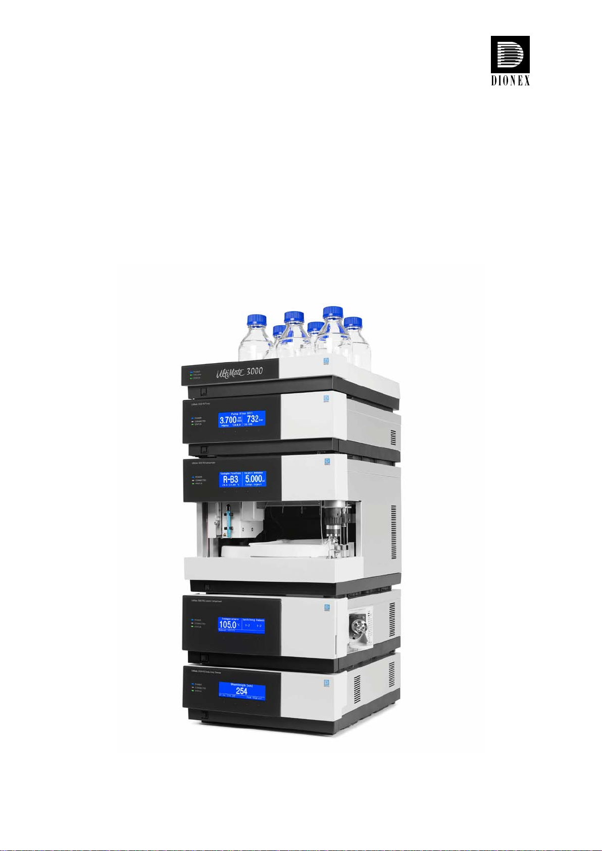
In many cases, bench space is limited; hence the Dionex UltiMate 3000 systems are designed to
consume as li ttle space as possible. We as sume that a single-stack setup is the most common
case; therefore, the LCi capillary kits have been optimized for this scenario.
Figure 1: UltiMate 3000 system as a single stack
Note: Figure 1 illustrates the course of the flexible Viper capillaries in general.
Dionex recommends installing all capillaries inside the modules as needed.
Page 2 Rev. 02 January 2010
© 2010 Dionex
UltiMate® 3000 Viper™ Capillary Kits fo r In telligent LC (LCi) System Solutions
Quick Installation Guides
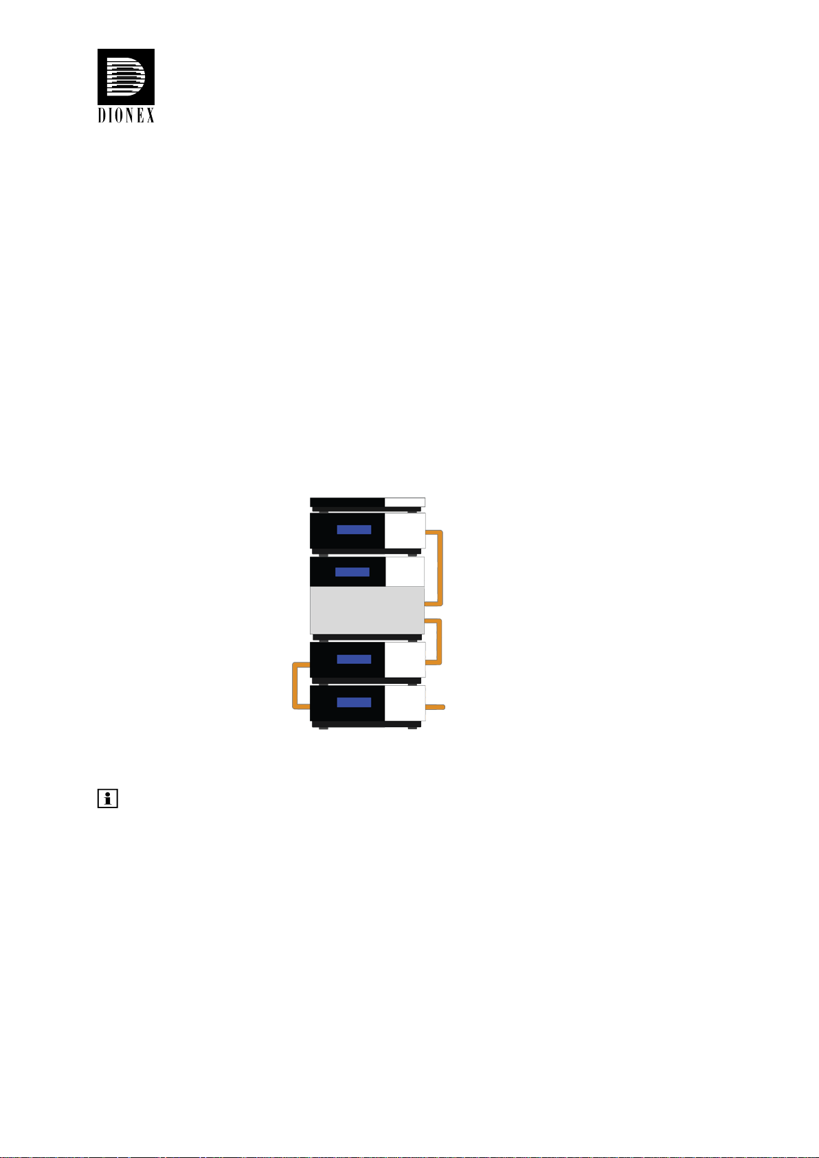
1.3.2 Dual-Stack
Whenever bench space is of no concern but reduced s ystem height is more important to users,
the s ystem can be configured as a dual-stack. Several different combinations are conceivable,
depending on the kind and number of modu les i ncl ude d in a system. The Viper LCi capillary kits
have been carefully developed to cover as many individual situations as possible for the use of
all UltiMate 3000 modules in single-stack or dual-stack configurations. In some cases, however,
limitations may occur. The details on possible limitations will be outlined in the according
paragraphs. Figure 2 illustrates the two most co mm on dua l-stack configurations.
Figure 2: Dual-stack with U-shaped flow profile Figure 3: Dual-stack wit h Z -shaped flow profile
1.4 Viper Connections
When working with small column volumes, capillaries and connections require special attention.
But even with conventional columns and moderate pressures, mediocre connections can cause
retention time shifts and peak distortions. Conventional stainless steel HPLC connectors use a
ferrule and a nut to establish connections. A flaw of the conventional design is that a void
volume-free connection is not guaranteed, particularly when changing the tubing between
differently shaped threads (e.g. when changing a column). Viper connectors provide zero dead
volume by sealing at the tubing tip, hence ensuring optimized connections.
Viper is a revolutionary finger tight fitting system, which provides ease of use and dead-volumefree plumbing of conventional HPLC and modern UHPLC systems. Together with 1/32” flexible
stainless steel (SST) capillaries, it opens a new dimension in modern liquid
chromatography (LC). Viper improves chromatographic results, independent from column
brands and s ystem back pressures, and allows for connecting LC modules, valves, and columns
quickly, easily, a nd repr oducib ly without any additional tools.
Even though Viper withstands UHPLC backpressures of up to 1,200 bar (17,400 psi), it is a
finger tight fitting system, which requires only small torques to seal. Therefore, it is essential to
obey the following guidelines to avo id damag e s by over-tightening.
January 2010 Rev. 02 Page 3
© 2010 Dionex
UltiMate® 3000 Viper™ Capillary Kits fo r In telligent LC (LCi) System Solutions
Quick Installation Guides
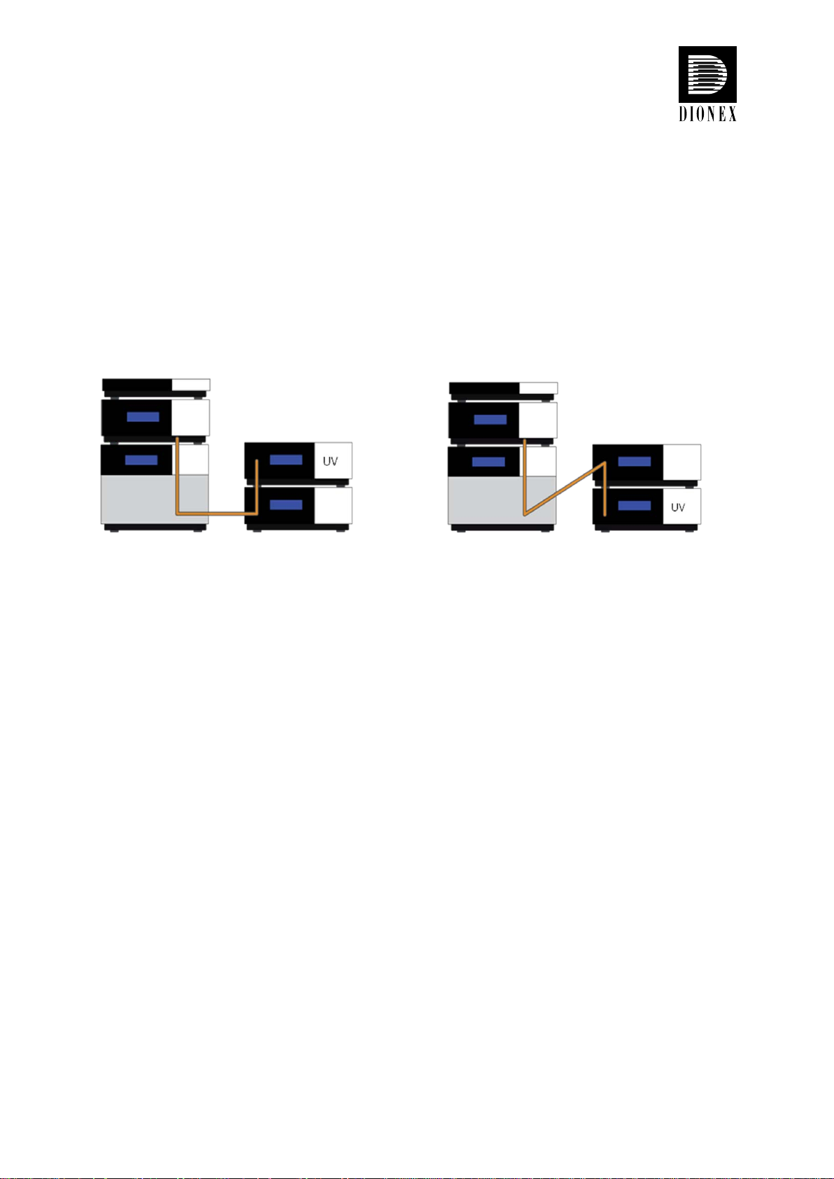
Figure 4: Schematic for tightening a Viper fitting
Attach Viper to the target thread and tighten the screw slowly until you feel the very first
resistance. This is the 0° mark. Do not use tools other than the black knurl for opening and
closing a connection.
Tighten the screw clockwise to an angle between 0° and 45° and start operating your LC system
at the desired working pressure. Verify that all connections seal properly. Usually, the Viper
fitting is tight for pres sure s up to 1,200 bar (17,400 psi) af te r th e first attemp t.
If leakage occurs under these conditions, tighten the screw(s) gradually further until the
connection seals properly. Do not turn the screw beyond an angle of 90° to avoid damages of the
PEEK seal by over-tightening. Do not a pply brute force.
To extend the life-time of Viper, open and close connections only at atmospheric system
pressures. Opening and closing Viper connections at high system pressures may reduce the lifetime of the fi tt ing system.
If you are unable to get a Viper connection tight, call your local Dionex representative or replace
it with a new capillary.
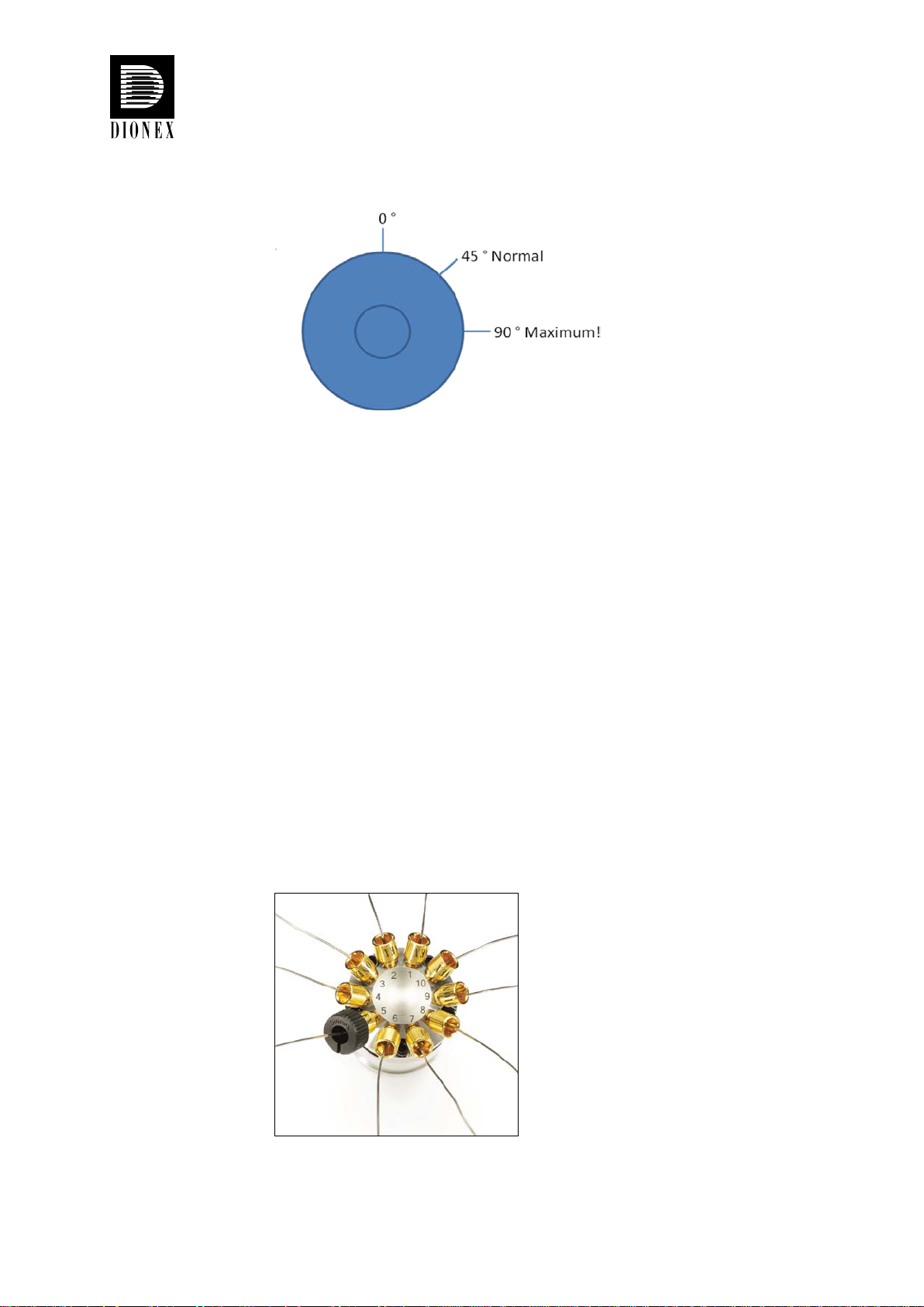
Figure 5: 10-port valve equipped with Viper fittings
Page 4 Rev. 02 January 2010
© 2010 Dionex
UltiMate® 3000 Viper™ Capillary Kits fo r In telligent LC (LCi) System Solutions
Quick Installation Guides
1.5 Viper Capillar y Kits and Packaging
1.5.1 Capillary Kits for Single Stacks
All UltiMate 3000 RS systems are delivered wi th a dedicated set of 3 Viper capillaries for
system plumbing. In addition, dedicated Viper capillary RS and SD kits containing
3 capillaries each are available to equip Dionex UltiMate 3000 systems with Viper.
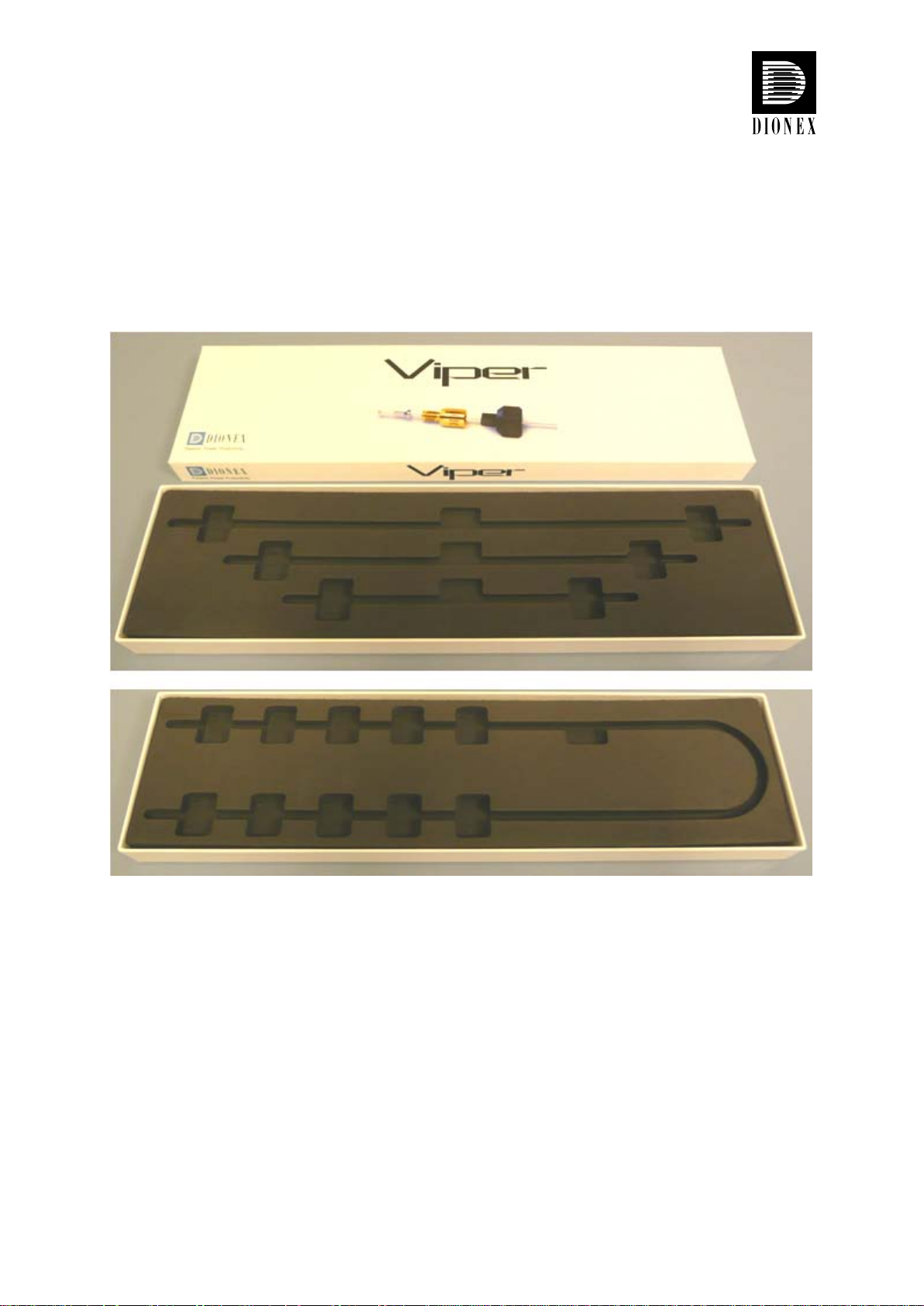
Figure 6: Packaging box for Viper RS and SD capillary kits for UltiMate 3000 systems (single system, see
Figure 1). T he opposite side o f the foam inlay allows for shipment of Viper capillaries with lengths of up to
1,000 mm.
January 2010 Rev. 02 Page 5
© 2010 Dionex
UltiMate® 3000 Viper™ Capillary Kits fo r In telligent LC (LCi) System Solutions
Quick Installation Guides
1.5.1.1 Scope of Delivery
1.5.1.1.1 Viper Capillary Kit , RS System
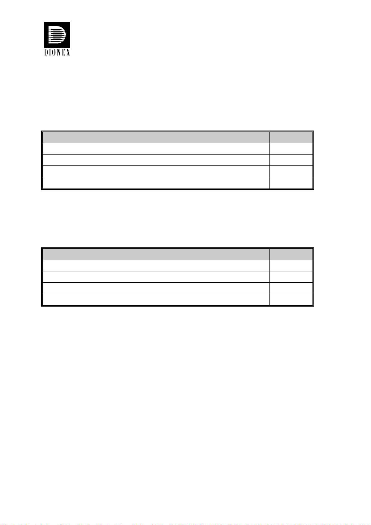
Table 1: Scope of delivery for the Viper capillary kit, RS sy stem (P/N 6040.2301)
Description Quantity
Viper capillary (SST), ID x L 0.18 mm/0.007” x 450 mm 1 pc.
Viper capillary (SST), ID x L 0.13 mm/0.005” x 350 mm 1 pc.
Viper capillary (SST), ID x L 0.13 mm/0.005” x 250 mm 1 pc.
Viper Installation and Operation Guide, short version 1 pc.
1.5.1.1.2 Viper Capillary Kit, SD System
Table 2: Scope of delivery for the Viper capillary kit, SD system (P/N 6040.2302)
Description Quantity
Viper capillary (SST), ID x L 0.18 mm/0.007” x 450 mm 1 pc.
Viper capillary (SST), ID x L 0.18 mm/0.005” x 350 mm 1 pc.
Viper capillary (SST), ID x L 0.18 mm/0.005” x 250 mm 1 pc.
Viper Installation and Operatio n Guide, short version 1 pc.
Page 6 Rev. 02 January 2010
© 2010 Dionex
UltiMate® 3000 Viper™ Capillary Kits fo r In telligent LC (LCi) System Solutions
Quick Installation Guides
1.5.2 LCi Capillary Kits
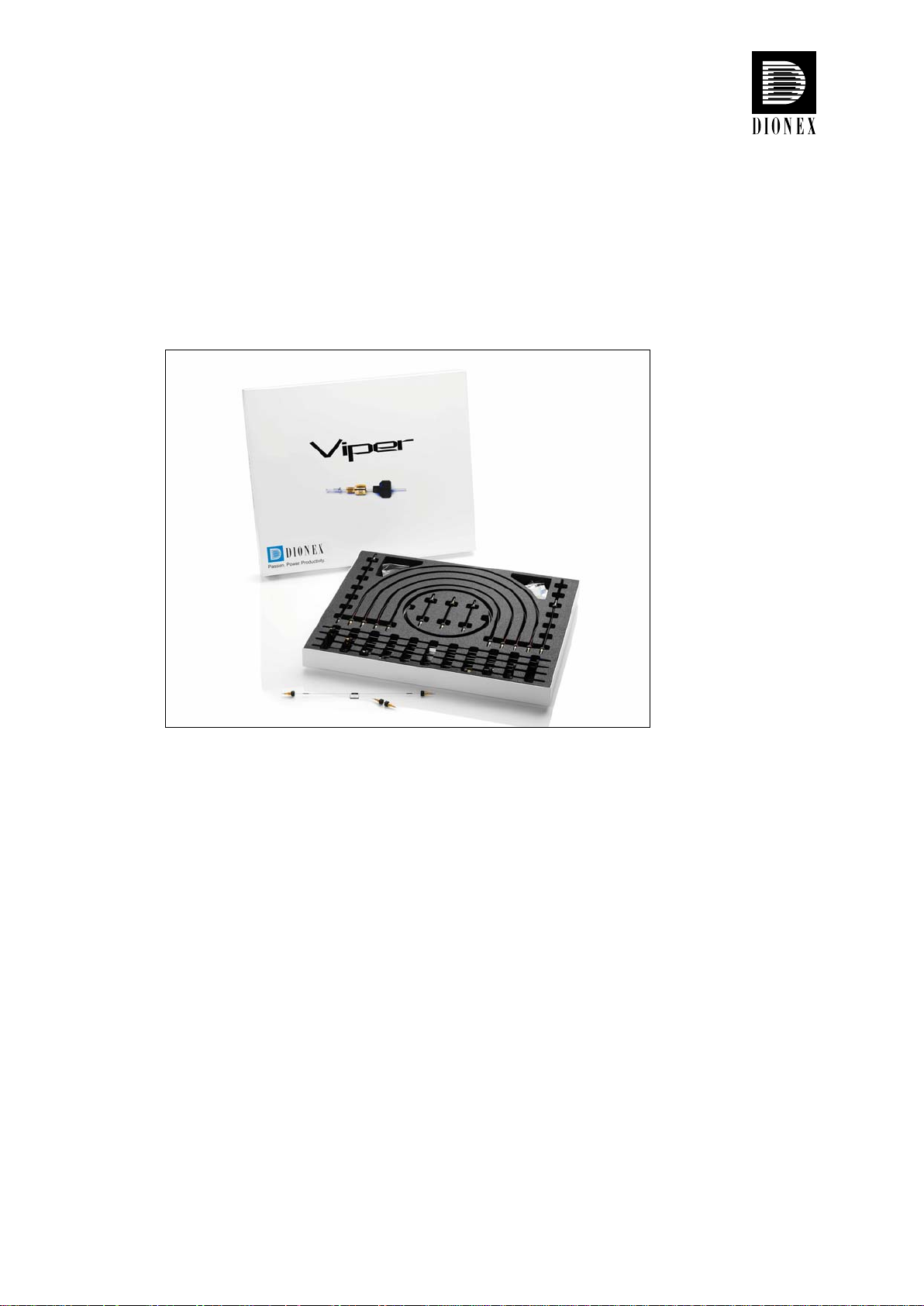
All Viper LCi capillary kits are delivered in a high-quality box with a foam inlay.
Independent of the ordered kit, you will always receive the same box, accommodating all
necessary accessories and capillaries for your individual LCi kit.
Figure 7: Packaging box for all Viper LCi capillar y ki ts.
January 2010 Rev. 02 Page 7
© 2010 Dionex
UltiMate® 3000 Viper™ Capillary Kits fo r In telligent LC (LCi) System Solutions
Quick Installation Guides
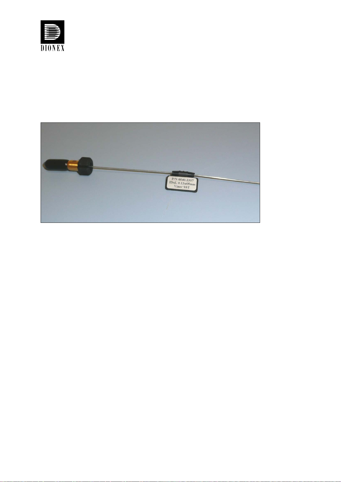
1.6 Viper Labeling
Each Viper capillary comes with a labeling clip. This clip can be easily detached and
reattached to 1/16” and 1/32” OD capillaries. In addition, a set of 5 blank clips and stickers is
supplied for individual labeling purposes.
Figure 8: Removable labeling clip with sticker for individual capillary labeling.
Page 8 Rev. 02 January 2010
© 2010 Dionex
UltiMate® 3000 Viper™ Capillary Kits fo r In telligent LC (LCi) System Solutions
Quick Installation Guides
1.7 General System Preparation
Allow the system modules to adapt to ambient temperature for 4 hours to allow for potential
condensation to evaporate. Do not connect the units to the mains during this period. If
condensation is still detected after 4 hours, allow the system to continue to warm up to
ambient temperature without connecting it to the mains, until all condensation is completely
gone.
Place the system on a firm and level surface that is free of vibrations. Make sure that the
surface is resis tant against LC solvents. Avoid lo cations with extreme changes in temperature
(such as direct sunlight or drafts) and high air humidity.
Note: For information about the power and communication connections
(LAN, USB) as well as the installation procedures for other components,
such as the Activ e Rear-Seal Wash S ystem, please refer t o the operatin g
instructions of the system components.
1.8 Connecting the Eluent Line t o the Solvent Re s e rvoir
1. Feed the eluent line through the retaining guide and then into the opening in the reservoir
cap.
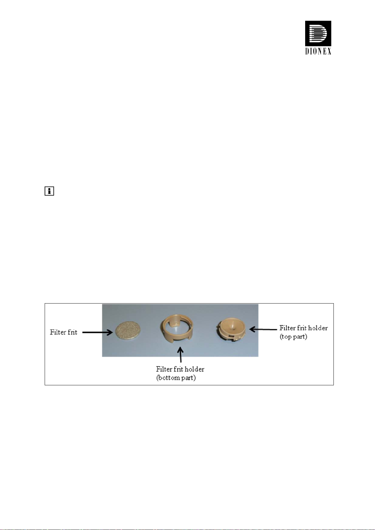
2. Assemble the eluent filter
Figure 9: Eluent filter components
3. Slide the eluent filter assembly onto t he end of the eluent line. Verify that the end of the
eluent line is cut straight and is not deformed. If necessary, cut the tubing with a sharp
knife or blade. Use only the eluent lines shipped with the solvent rack.
4. Place the complete assembly in the solvent reservoir.
5. Hand-tighten the solvent reservoir caps.
January 2010 Rev. 02 Page 9
© 2010 Dionex
 Loading...