

Page 1
© 2012 Thermo Fisher Scientific Inc.
UltiMate 3000 RSLCnano
Standard Applications
Revision: V1.0 R3
Date: January 2012
Doc.no. 4820.4103
Page 2

UltiMate 3000 RSLCnano – Standard Applications
1
Page 3

UltiMate 3000 RSLCnano – Standard Applications
Table of Contents
1 Introduction ................................................................................................................ 4
1.1 Additional Documents ............................................................................................... 5
2 Application Setup ....................................................................................................... 6
2.1 General Recommendations for Applications............................................................. 6
2.1.1 Connections ........................................................................................................ 6
2.1.2 Sample Preparation ............................................................................................. 7
2.1.3 Mobile Phases ..................................................................................................... 8
2.2 Installing the UltiMate 3000 RSLCnano system ....................................................... 9
2.3 Application Overview ............................................................................................. 12
2.4 Direct Injection onto a Nano Column ..................................................................... 13
2.4.1 Hardware Layout .............................................................................................. 13
2.4.2 Fluidic Setup ..................................................................................................... 15
2.4.3 Installation Tips ................................................................................................ 15
2.4.4 Testing the Application .................................................................................... 16
2.4.5 Large Volume Injections .................................................................................. 16
2.5 Direct Injection onto a Capillary Column ............................................................... 18
2.5.1 Hardware Layout .............................................................................................. 18
2.5.2 Fluidic Setup ..................................................................................................... 19
2.5.3 Installation Tips ................................................................................................ 20
2.5.4 Testing the Application .................................................................................... 20
2.6 Pre-concentration onto a Nano Column .................................................................. 21
2.6.1 Hardware Layout .............................................................................................. 21
2.6.2 Fluidic Setup ..................................................................................................... 22
2.6.3 Installation Tips ................................................................................................ 23
2.6.4 Testing the Application .................................................................................... 23
2.7 Pre-concentration onto a 200 µm Monolithic Column ............................................ 25
2.7.1 Hardware Layout .............................................................................................. 25
2.7.2 Fluidic Setup ..................................................................................................... 26
2.7.3 Installation Tips ................................................................................................ 27
2.7.4 Testing the Application .................................................................................... 27
2.8 Pre-concentration on a Capillary Column ............................................................... 29
2.8.1 Hardware Layout .............................................................................................. 29
2.8.2 Fluidic Setup ..................................................................................................... 30
2.8.3 Installation Tips ................................................................................................ 31
2.8.4 Testing the Application .................................................................................... 31
2.9 2D Salt Steps with Nano Column ............................................................................ 32
2.9.1 Hardware Layout .............................................................................................. 32
2.9.2 Fluidic Setup ..................................................................................................... 33
2.9.3 Installation Tips ................................................................................................ 34
2.9.4 Testing the Application .................................................................................... 35
2.9.5 Salt Solutions Preparation ................................................................................ 36
2.10 Automated off-line 2D LC of Peptides, micro SCX x nano RP .............................. 37
2.10.1 Hardware Layout .............................................................................................. 37
2.10.2 Fluidic Setup ..................................................................................................... 39
2.10.3 Installation Tips ................................................................................................ 40
2.10.4 Testing the Application .................................................................................... 41
2.11 Automated off-line 2D LC, Cap RP (basic) x nan RP (acidic) ............................... 42
2.11.1 Hardware Layout .............................................................................................. 42
2.11.2 Fluidic Setup ..................................................................................................... 43
2
Page 4

UltiMate 3000 RSLCnano – Standard Applications
2.11.3 Installation tips ................................................................................................. 44
2.11.4 Testing the application ..................................................................................... 44
2.12 Tandem nano LC ..................................................................................................... 46
2.12.1 Hardware Layout .............................................................................................. 46
2.12.2 Fluidic Setup ..................................................................................................... 47
2.12.3 Installation Tips ................................................................................................ 48
2.12.4 Testing the Application .................................................................................... 48
3 FAQ ........................................................................................................................... 50
3.1 Interpreting a Chromatogram .................................................................................. 50
3.2 Troubleshooting nano LC peptide Applications...................................................... 50
3.3 The use of TFA and FA ........................................................................................... 52
3.4 Minimizing Baseline Noise ..................................................................................... 52
3.4.1 Drift .................................................................................................................. 52
3.4.2 Unstable Baseline ............................................................................................. 53
4 Appendix – Traditional Capillary Connections .................................................... 54
5 Appendix – Common Spare Parts in nano LC...................................................... 56
3
Page 5

UltiMate 3000 RSLCnano – Standard Applications
1 Introduction
This document describes the standard setup, recommended experimental conditions and
testing procedures to run standard applications on the Thermo Scientific Dionex UltiMate
3000 RSLCnano system.
Notes: This document is intended for Thermo Fisher Scientific (or authorized)
service personnel as well as customers to assist in the installation and
system test of UltiMate 3000 RSLCnano systems.
It is assumed that the individual using this manual has sufficient training in
the installation and usage of analytical instrumentation and is aware of the
potential hazards including (but not limited to) electrical hazards, chemical
solvent hazards, exposure to UV radiation and the exposure to pressurized
solvents.
At various points throughout the manual, messages of particular importance are indicated by
the following symbols:
Tip: Indicates general information intended to optimize the installation and
setup steps or the performance of the instrument.
Important: Indicates that failure to take note of the accompanying information may
result in damage to the instrument.
Warning: Indicates that failure to take note of the accompanying information may
result in personal injury.
This manual is provided "as is." Every effort has been made to supply complete and accurate
information and all technical specifications have been developed with the utmost care. The
information contained in this manual should not be construed as a commitment by Thermo
Fisher Scientific. Thermo Fisher Scientific assumes no responsibility for any errors that may
appear in this document. This document is believed to be complete and accurate at the time of
publication. In no event shall Thermo Fisher Scientific be liable for incidental or
consequential damages in connection with or arising from the use of this document.
The information contained in this document is subject to change without notice.
4
Page 6

UltiMate 3000 RSLCnano – Standard Applications
All rights reserved, including those for photomechanical reproduction and storage on
electronic media. No part of this publication may be copied or distributed, transmitted,
transcribed, stored in a retrieval system, or transmitted into any human or computer language,
in any form or by any means, electronic, mechanical, magnetic, manual, or otherwise, or
disclosed to third parties without the express written permission of Thermo Fisher Scientific
Inc.
Trademarks
Analyst is a registered trademark of AB Sciex.
Compass and Hystar are trademarks of Bruker Daltronics.
Nitronic is a registered trademark of AK Steel Corp.
PEEK is a trademark of Victrex PLC.
PharMed is a registered trademark of Saint -Gobain Performance Plastics.
Windows and Windows Vista are registered trademarks of Microsoft Corp.
All other trademarks are property of Thermo Fisher Scientific Inc. and its subsidiaries
1.1 Additional Documents
In addition to the information provided in this manual, the following documents are available:
• Operating Instructions of the individual modules
• Installation Qualification manual for installation of the UltiMate 3000 RSLCnano
• Micro Fraction Collection Option for the Thermo Scientific Dionex UltiMate WPS-
3000PL Nano/Cap Autosampler
• Application/technical notes to be published on the Dionex website
In addition to these documents, Chromeleon templates are available for these applications.
Please contact your local Thermo Scientific sales or service representative to obtain the
templates.
5
Page 7
UltiMate 3000 RSLCnano – Standard Applications
2 Application Setup
2.1 General Recommendations for Applications
The experimental conditions for each application are presented together with related
information such as schematics, installation tips and examples, results and interpretation.
2.1.1 Connections
All high-pressure fittings used in the applications on the UltiMate 3000 RSLCnano system are
made with nanoViper. nanoViper is a fingertight high-pressure fitting that is dead volume free
by design and back pressure resistant up to 1000 bar. The fittings are assembled in the factory
to ensure consistent fittings and prevent experimental failure due to bad connections.
Figure 1: Example of a nanoViper fitting
1. Install nanoViper as any fingertight fitting.
2. Do not over-tighten connections (general guide line: finger-tight + maximum an
additional one eighth-turn).
3. Remove the black knurled screw.
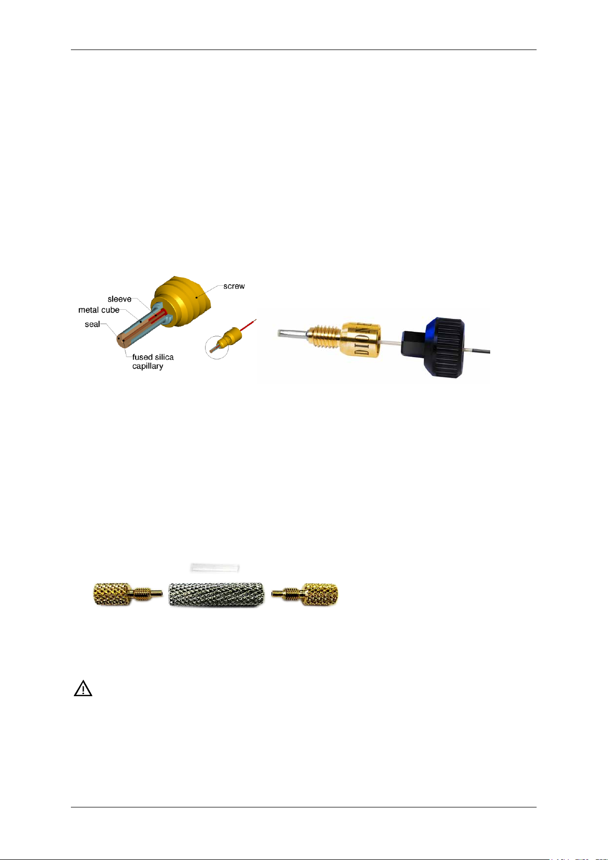
The outlet of the nano columns is fitted with a nano connector. This is a dedicated connection
designed to offer maximum flexibility in connecting fused silica capillaries and offering
pressure stability up to 300 bars. The nano connector uses a special sleeve to ensure pressure
tightness. The assembly of a nano connector is described step by step below.
Figure 2: nano connector layout
• Use a new nano connector sleeve (P/N 6720.0391) for each connection
Important: Do NOT use a PTFE sleeve. The size does not match the nano
connector and the pressure resistance is much lower.
6
Page 8
UltiMate 3000 RSLCnano – Standard Applications
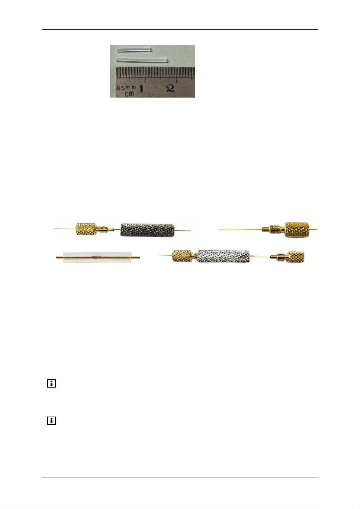
Nano connector sleeve (~1.1 cm)
PTFE (1.8 cm)
Figure 3: nano connector (top) and PTFE (bottom) sleeve comparison
1. Slide the golden nut and silver union onto one of the fused silica outlets; slide the
second golden union on the other fused silica end. (→ Figure 4a and Figure 4b)
2. Slide the nano connector sleeve onto the fused silica, slide the other end of the fused
silica into the nano connector sleeve and make sure the connection is dead volume free.
Figure 4c
3. Tighten the golden nuts equally fingertight to ensure the nano connector sleeve is
centered in the silver union. Figure 4d
4. For traditional fittings, for example, PTFE sleeves see Appendix – Traditional Capillary
Connections (page 54)
a
b
c
Figure 4: Using the nano connector
d
2.1.2 Sample Preparation
• Follow the instructions provided with the test sample and use the solvents as indicated.
• After re-dissolving the sample wait at least 15 min before further diluting it.
o Use water with a minimum of 2 % ACN and appropriate ion-pairing agent to
dissolve.
o Dilution can be done in the same solvent or with water with appropriate ion-pairing
agent.
Tip: To limit the risks of peptides or proteins adsorption on the walls of the vials,
Thermo Fischer Scientific recommends using glass inserts (Polypropylene vials
for WPS with glass insert, 250 µL, set of 25, P/N 6820.0027).
Tip: When using IEX columns, make sure that the sample solvent contains a very
limited amount of salt and is at the right pH level (for example, adjust to pH 3
when using a SCX column to separate peptides).
7
Page 9

UltiMate 3000 RSLCnano – Standard Applications
2.1.3 Mobile Phases
• Always use fresh solvents.
• When running online multidimensional approaches, make sure that the mobile phase of
the first dimension will allow for trapping the sample on the (trap) column used on the
second dimension.
• For example, do not use phosphate buffers from SCX separations as loading solvent in
RP separations.
• Thermo Fischer Scientific recommends replacing (aqueous) solvents at least once every
two weeks.
Tip: Replace solvents completely; do not ’top up’ to avoid unwanted components
building up in the mobile phases.
8
Page 10
UltiMate 3000 RSLCnano – Standard Applications
SRD-3400, SRD-3200 with degassing or
NCS-3500RS module featuring
VWD-3400RS with flow cells for
WPS-3000TPL RS
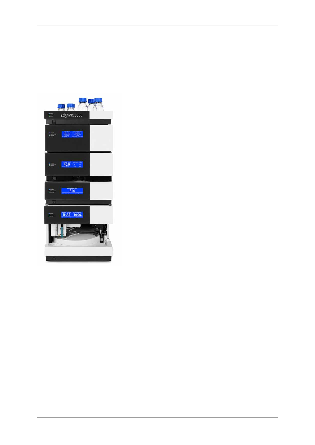
2.2 Installing the UltiMate 3000 RSLCnano System
The general UltiMate 3000 RSLCnano system overview is shown in Figure 5. The modular
nature of the Thermo Scientific Dionex UltiMate 3000 platform does allow modifications to
this layout.
SR-3000 without degassing.
- NC pump, up to 800 bar
- Loading pump, micro Titanium up to 500 bar
- Column compartment with up to two switching valves
Optional:
- NCP-3200RS
- PAEK valve
Figure 5: RSLCnano system overview
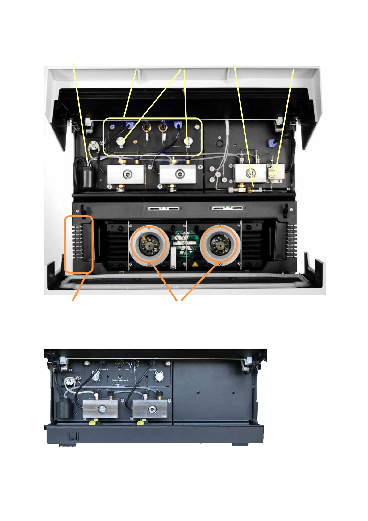
Figure 6 shows the interior of the NCS-3500RS module. The module consists of two pumps
and an integrated column compartment. The most important elements required for system
setup are indicated in the picture.
Figure 7 shows the interior of the NCP-3200RS module. This module contains only the
NC_Pump, but is identical in capabilities and performance as the NC_Pump in the NCS3500RS.
- nano (3nL),
- capillary (45 nL)
- micro (180 nL) LC
- Temperature controlled autosampler equipped with a
1000 bar switching valve
- Optional:
8-port valve (350 bar) for automated off-line
applications
9
Page 11
UltiMate 3000 RSLCnano – Standard Applications
NC_Pump
Loading pump
Rear seal wash system
Flow meter
Purge screws
Inline filter
Purge screw
Tubing guides
Snap-in valves
Column compartment
Figure 6: Detailed overview of the NCS-3500RS interior
Figure 7: Detailed overview of the NCP-3200RS interior, components are identical to the NC_Pump in the NCS3500RE
10
Page 12

UltiMate 3000 RSLCnano – Standard Applications
1
To control the module, Thermo Scientific Dionex Chromeleon 6.80 SR8 (or later) or
2
Prepare electrical and USB connections, power up modules, and then prepare server
3
Prepare solvents and install them according to the application.
Important
Use the PEEK solvent inlet filter frits in both, the NC pump and loading pump
Degassing of the loading pump solvents is required when the loading pump is
4
Purge both blocks of the NC pump (min 30 min.), while assisting with a syringe until
Make sure that the purge screws of the NC_Pump are entirely opened.
5
Purge flow meter for 30 min.
The purge time with a nano flow selector is 30 minutes. For capillary and micro
6
Perform pressure sensor offset calibration, using Chromeleon Diagnostics. To do so, open
7
Perform viscosity calibration using Chromeleon Diagnostics or select default viscosities
To see the solvent list for which default viscosities are available, use the
8
Prepare all fluidics using the provided nanoViper connection tubing.
Do not overtighten the fingertight connection!
Before the parts of the application kit are installed, the UltiMate 3000 RSLCnano system has
to be prepared and primed. To prepare the system, the following steps are required. For more
details, see the operating instructions for the respective module.
DCMSLink version 2.8 (or later) and appropriate license are required.
configuration.
- NC pump channels A and B
- Loading pump channels A, B, and C (10-50% isopropanol in water for unused
channels)
- Rear seal wash solvent (~10% isopropanol in water)
- Autosampler wash solvent (~10% isopropanol 0.1% FA in water).
solvent lines.
Tip
used for gradient formation or the flow rate is above 20 µL/min.
liquid exits the purge lines. Purge all channels of the loading pump (minimum 10 min).
Tip
Tip
flow selectors purge times may be shorter. Please refer to the NCS-3500RS or
NCP-3200RS manual for details.
the More options panel of the NC_Pump and click the related button.
from the available viscosity list.
Tip
Commands dialog (F8) and scroll to Pump module NC_Pump
%A_Viscosity (%B_Viscosity).
Tip
11
Page 13
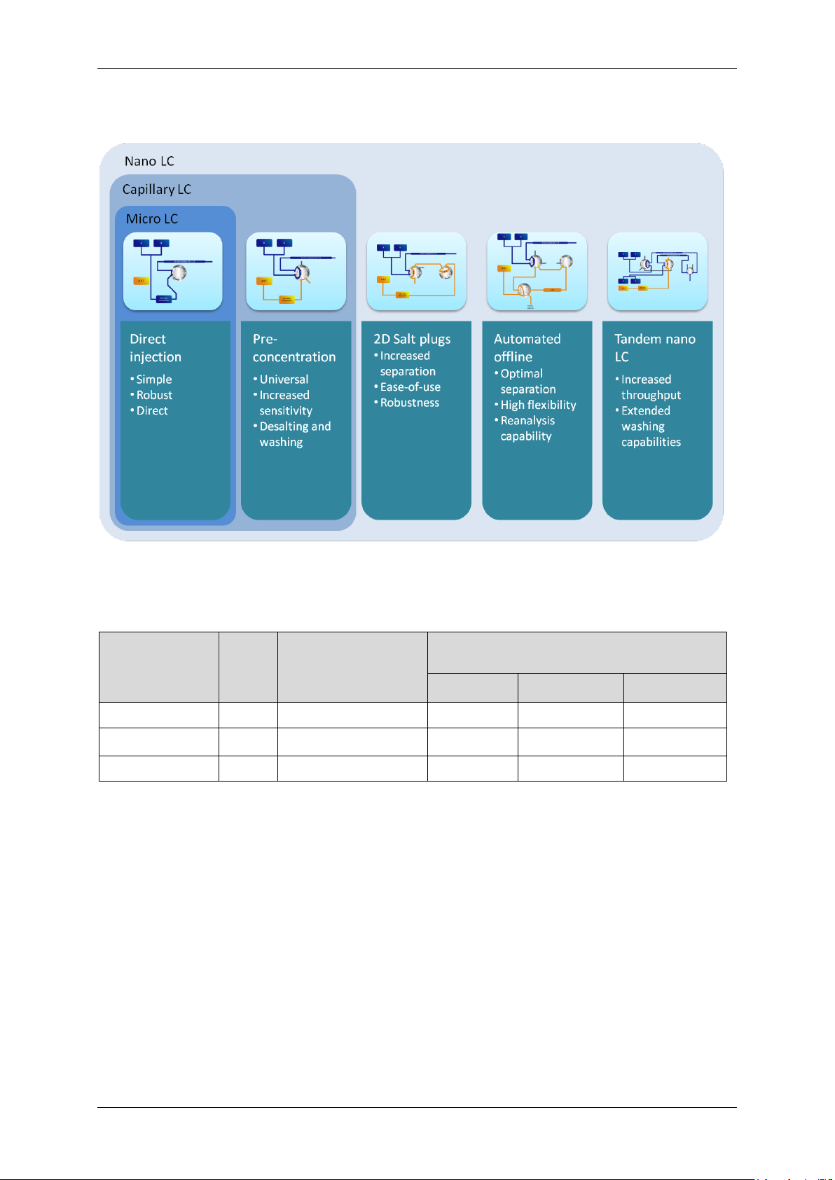
2.3 Application Overview
UltiMate 3000 RSLCnano – Standard Applications
Table 1: Property overview of different flow selectors
Flow Selector
Type
Nano Nan 6041.0002 500 nL/min 50 nL/min* 1000 nL/min
Capillary Cap 6041.0003 5 µL/min 500 nL/min 10 µL/min
Micro Mic 6041.0014 25 µL/min 2.5 µL/min 50 µL/min
*Lower flow rates are available upon request
I.D. P/N Total Flow Rate
(Sum of channel A and B)
Nominal Minimum Maximum
12
Page 14
UltiMate 3000 RSLCnano – Standard Applications
2.4 Direct Injection onto a Nano Column
2.4.1 Hardware Layout
The preferred setup is presented in
Figure 8 and consists of:
SR-3000 5035.9200
NCP-3200RS 5041.0030
VWD-3400RS 5074.0010
3 nL flow cell 6074.0270
WPS-3000TPL RS 5826.0020
Application kit: 6720.0300
Figure 8: Setup for a Direct Injection experiment onto a
nano column
13
Page 15
UltiMate 3000 RSLCnano – Standard Applications
The alternative setup is presented in
Figure 9 and consists of:
SRD-3400 5035.9245
NCS-3500RS 5041.0010
VWD-3400RS 5074.0010
3 nL flow cell 6074.0270
WPS-3000TPL RS 5826.0020
Application kit: 6720.0300
Figure 9: Setup for a Direct Injection experiment onto a
nano column
14
Page 16
UltiMate 3000 RSLCnano – Standard Applications
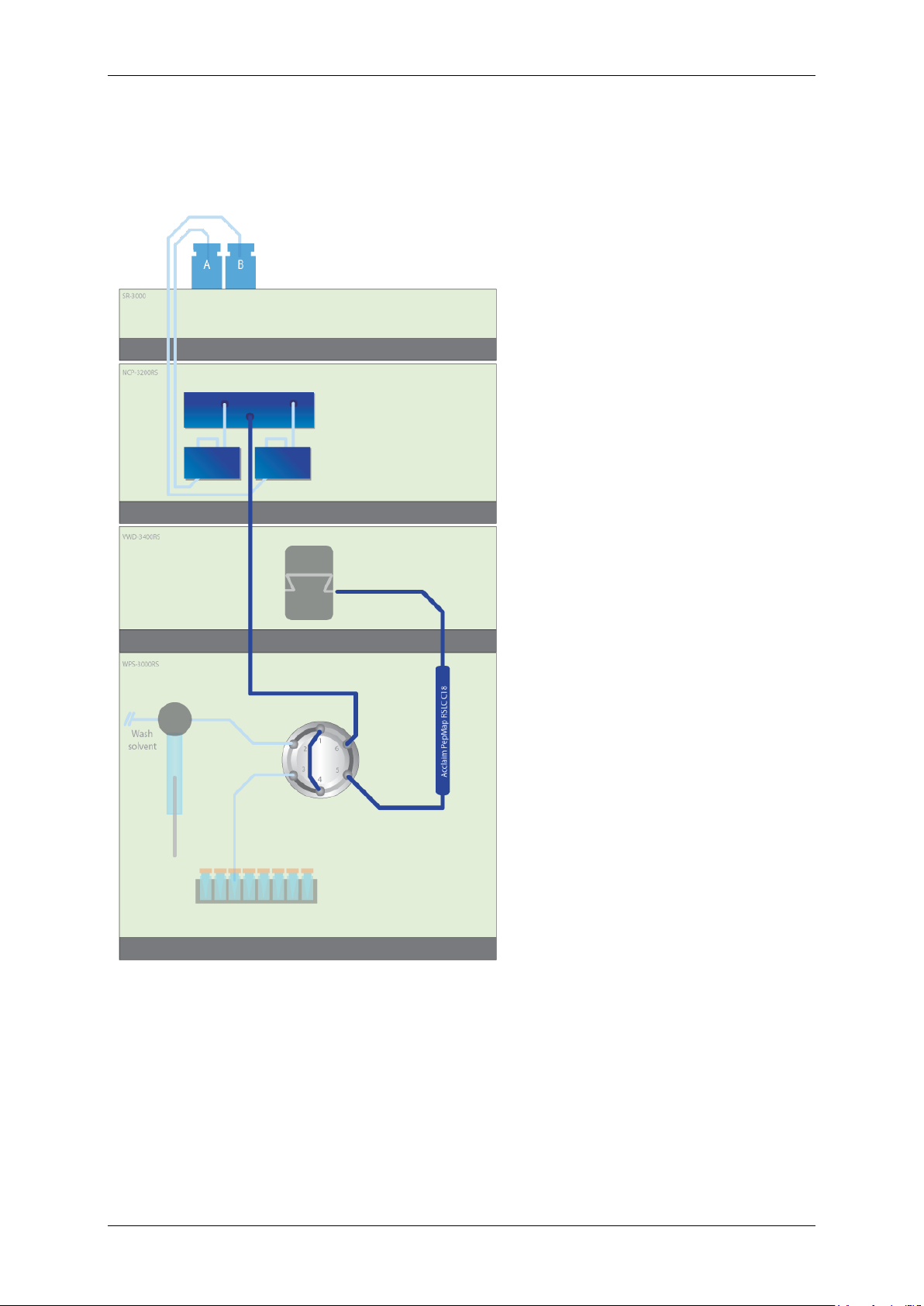
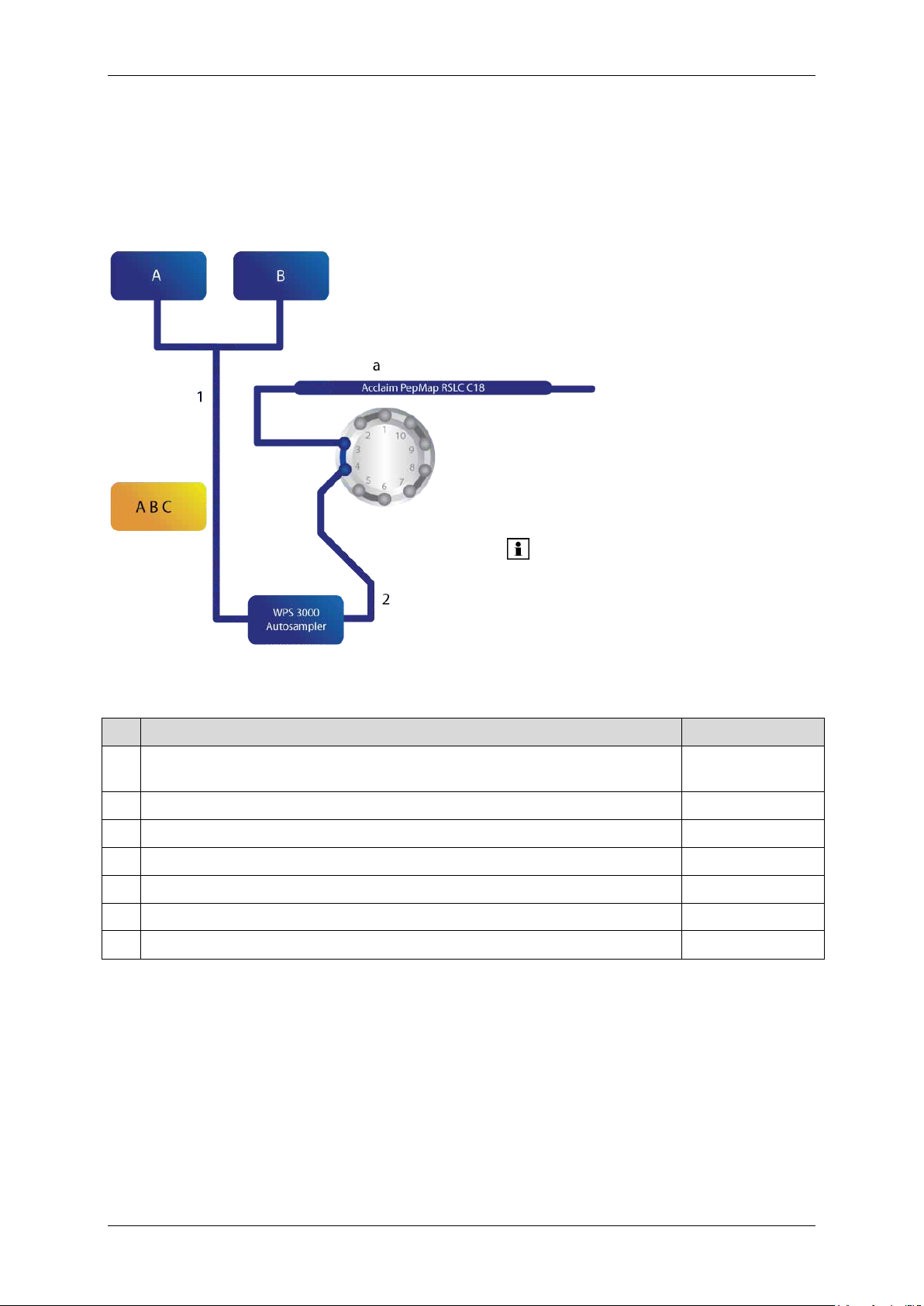
2.4.2 Fluidic Setup
Figure 10 presents the setup using the parts of the Direct Injection application kit. Columns
are marked with letters, tubing with digits, and the sample loop is installed in the WPS3000PL Autosampler
Tip: When no valve is
available, a union can be used to
connect the capillary column
(P/N 6040.2304)
Figure 10: Fluidic connections for a Direct Injection experiment onto a nano column
Table 2: UltiMate 3000 RSLCnano Direct Injection nano LC kit (P/N 6720.0300) contents
# Item Replacement P/N
75 µm I.D. x 15 cm, packed with Acclaim PepMap RSLC C18, 2 µm,
a
100Å, nanoViper
nanoViper capillary FS/PEEK sheathed 1/32" I.D. x L 20 µm x 750 mm 6041.5280
1
nanoViper capillary FS/PEEK sheathed 1/32" I.D. x L 20 µm x 550 mm 6041.5260
2
nanoViper sample loop 1 µL, FS/PEEK sheathed I.D. x L 100 µm x 127 mm 6826.2401
Polypropylene vials for WPS with glass insert, 250 µL, 25 pcs. 6820.0027
Polypropylene caps for WPS vials, 25 pcs. 6820.0028
Cytochrome C digest, 1.6 nmol, Lyophilized 161089
164534
2.4.3 Installation Tips
• Follow the General Recommendations for Applications (→ page 6).
• The impact of dwell (dead) volumes on reproducibility is very important. Improper
connections of the different elements are the most likely cause of failure for this
application.
15
Page 17
UltiMate 3000 RSLCnano – Standard Applications
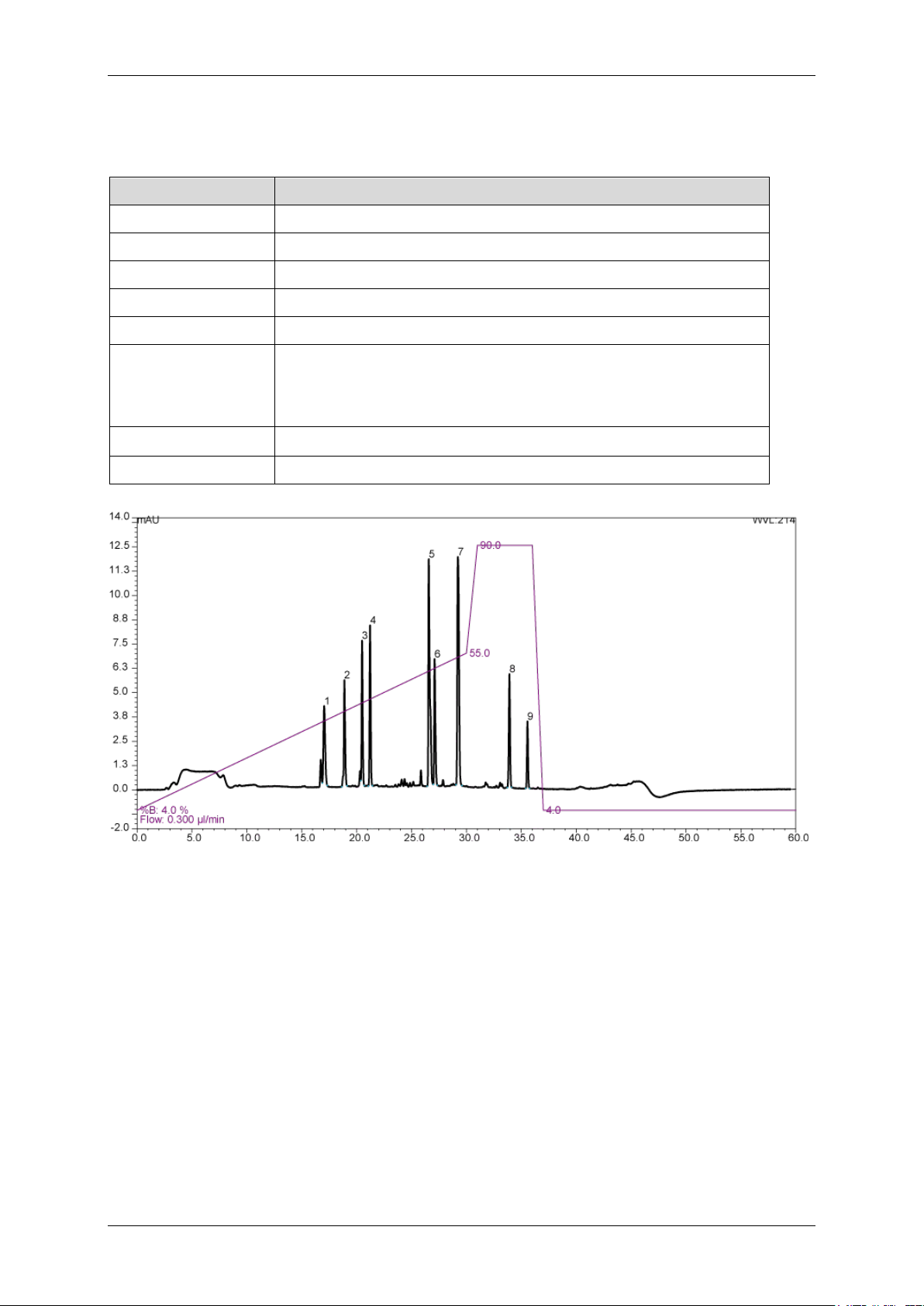
2.4.4 Testing the Application
The direct injection can be tested using the following conditions:
Property Setting
Mobile phase A 100% water + 0.05% TFA
Mobile phase B 20%/80% (v/v) water/ACN + 0.04% TFA
Sample Cytochrome C digest 1 pmol/μL, prepared according to the instruction sheet
Injection volume 1 μL
UV detection 214 nm
Gradient 4% to 55% B in 30 min
90% B for 5 min
25 min equilibration
WPS temperature
Flow rate 300 nL/min (nano flow selector)
5°C (WPS-3000(B)T only)
Figure 11: Typical chromatogram for a Direct Injection of 1 pmol Cyt C onto a nano column
For details on interpretation and troubleshooting of the Cytochrome C nano LC separation,
see the FAQ section on page 50.
2.4.5 Large Volume Injections
Typically direct injections in nano LC are performed with 1 µL loop sizes to minimize the
gradient delay. Larger volume injections are performed with a pre-concentration setup. The
WPS-3000PL autosampler series allows for a custom injection program (UDP) to switch back
the injection valve after sample loading to bypass the loop. This way a larger sample volume
can be injected and pre-concentrated directly onto the nano column, without using a preconcentration setup.
16
Page 18

UltiMate 3000 RSLCnano – Standard Applications
The advantage of such a setup is the ease of use and a minimum loss of peptides, especially
hydrophilic ones. The prerequisites of this setup are desalted samples, since all that is injected
will enter the MS, and an investment of extra analysis time to accommodate the loading of
sample with nano flow.
17
Page 19

2.5 Direct Injection onto a Capillary Column
The recommended setup is
2.5.1 Hardware Layout
UltiMate 3000 RSLCnano – Standard Applications
presented in Figure 12 and consists
of:
SRD-3400 5035.9245
NCS-3500RS 5041.0020
VWD-3400RS 5074.0010
45 nL flow cell 6074.0280
WPS-3000TPL RS 5826.0020
Application kit: 6720.0305
Figure 12: Setup for a Direct Injection experiment onto a
capillary column
18
Page 20

UltiMate 3000 RSLCnano – Standard Applications
(P/N 6040.2304)
2.5.2 Fluidic Setup
Figure 13 presents the setup using the parts of the Direct Injection application kit. Columns
are marked with letters, tubing with digits, and the sample loop is installed in the
WPS-3000PL Autosampler.
Tip: When no valve is
available, a union can be used to
connect the capillary column
Figure 13: Fluidic connections for a Direct Injection experiment onto a capillary column
Table 3: UltiMate 3000 RSLCnano Direct Injection capillary LC Kit (P/N 6720.0305) contents
# Item Replacement P/N
300 µm I.D. x 15 cm, packed with Acclaim PepMap RSLC C18, 2 µm,
a
100Å, nanoViper
nanoViper capillary FS/PEEK sheathed 1/32" I.D. x L 50 µm x 750 mm 6041.5580
1
nanoViper capillary FS/PEEK sheathed 1/32" I.D. x L 50 µm x 550 mm 6041.5560
2
nanoViper sample loop 5 µL, FS/PEEK sheathed I.D. x L 200 µm x 159 mm 6826.2405
Polypropylene vials for WPS with glass insert, 250 µL, 25 pcs. 6820.0027
Polypropylene caps for WPS vials, 25 pcs. 6820.0028
Cytochrome C digest, 1.6 nmol, Lyophilized 161089
164537
19
Page 21

UltiMate 3000 RSLCnano – Standard Applications
2.5.3 Installation Tips
Follow the General Recommendations for Applications (→ page 6).
2.5.4 Testing the Application
The direct injection can be tested using the following conditions:
Property Setting
Mobile phase A 100% water + 0.05% TFA
Mobile phase B 20%/80% (v/v) water/ACN + 0.04% TFA
Sample Cytochrome C digest 8 pmol/μL, prepared according to the instruction sheet
Injection volume 1 μL
UV detection 214 nm
Gradient 4% to 55% B in 30 min
90% B for 5 min
25 min equilibration
WPS temperature
Flow rate 4 μL/min (capillary flow selector)
5°C (WPS-3000(B)T only)
Figure 14: Typical chromatogram for a Direct Injection of 8 pmol Cyt C onto a capillary column
20
Page 22

UltiMate 3000 RSLCnano – Standard Applications
2.6 Pre-concentration onto a Nano Column
2.6.1 Hardware Layout
The recommended setup is
presented in Figure 15 and consists
of:
SRD-3400 5035.9245
NCS-3500RS 5041.0010
10-port sw. valve 6041.0001
VWD-3400RS 5074.0010
3 nL flow cell 6074.0270
WPS-3000TPL RS 5826.0020
Application kit: 6720.0310
Figure 15: Setup for a Pre-concentration experiment onto a
nano column
21
Page 23

UltiMate 3000 RSLCnano – Standard Applications
2.6.2 Fluidic Setup
Figure 16 presents the setup using the parts of the Pre-concentration application kit. Columns
are marked with letters, tubing with digits, and the sample loop is installed in the
WPS-3000PL Autosampler
Tip: The schematic shows a 10-port switching valve, but this application can be
performed on a 6-port valve. Ensure that the relative positions of the connections
are correct, and update the valve switching in the Chromeleon templates if
necessary.
Figure 16: Fluidic connections for a Pre-concentration experiment onto a nano column
Table 4: UltiMate 3000 RSLCnano Pre-concentration nano LC kit (P/N 6720.0310) contents
# Item Replacement P/N
75 µm I.D. x 15 cm, packed with Acclaim PepMap RSLC C18, 2 µm, 100Å,
a
nanoViper
Nano Trap Column, 75 µm I.D. x 2 cm, packed with Acclaim PepMap100 C18,
b
3 µm, 100Å (set of 2) nanoViper
nanoViper capillary FS/PEEK sheathed 1/32" I.D. x L 20 µm x 350 mm 6041.5240
1
nanoViper capillary FS/PEEK sheathed 1/32" I.D. x L 75 µm x 650 mm 6041.5775
2
nanoViper capillary FS/PEEK sheathed 1/32" I.D. x L 75 µm x 550 mm 6041.5760
3
nanoViper capillary FS/PEEK sheathed 1/32" I.D. x L 20 µm x 750 mm 6041.5280
nanoViper sample loop 20 µL, FS/PEEK sheathed I.D. x L 250 µm x 408 mm 6826.2420
PTFE tubing, 500 µm I.D. 100 cm, used as waste tubing 6720.0077
4
Polypropylene vials for WPS with glass insert, 250 µL, 25 pcs. 6820.0027
Polypropylene caps for WPS vials, 25 pcs. 6820.0028
Cytochrome C digest, 1.6 nmol, Lyophilized 161089
164534
164535
1/16" Universal Fingertight Fitting, one-piece design, extra long thread, 4 pcs. 6720.0015
22
Page 24

UltiMate 3000 RSLCnano – Standard Applications
2.6.3 Installation Tips
• Follow the General Recommendations for Applications (→ page 6).
• The design of the nano trap column provides the easiest connections, but must only be
used in forward flush operation. Please check the indicated flow direction when
installing a nano trap column.
• If the loss of hydrophilic peptides is observed, the concentration of acetonitrile in the
loading solvent can be decreased down to 99/1 Water/ACN + 0.05% TFA or the use of
a stronger ion-pairing agent such as heptafluorobutyric acid (HFBA) can be considered.
2.6.4 Testing the Application
The pre-concentration setup can be tested using the following conditions:
Property Setting
Mobile phase A 100% water + 0.05% TFA
Mobile phase B 20%/80% (v/v) water/ACN + 0.04% TFA
Loading solvent 98%/2% (v/v) water/ACN + 0.05% TFA
Sample Cytochrome C digest 1 pmol/μL, prepared according to the instruction sheet
Injection volume 1 μL (partial loop fill of a 20µL loop)
UV detection 214 nm
Loading time 3 min (may vary with different injection volume/routine)
Gradient 4% to 55% B in 30 min
90% B for 5 min
25min equilibration
WPS temperature
Loading flow 5 μL/min
Flow rate 300 nL/min (nano flow selector)
5°C (WPS-3000(B)T only)
Figure 17: Typical chromatogram for Pre-concentration of 1 pmol Cyt C onto a nano column
23
Page 25

UltiMate 3000 RSLCnano – Standard Applications
To evaluate the result of the experiment, the chromatogram should look very similar to the
one obtained with direct injection.
For details on interpretation and troubleshooting of the Cytochrome C nano LC separation,
see the FAQ section on page 50.
Tip: The example chromatogram provided (Figure 17) has been obtained under optimal
conditions. When having difficulties to obtain a similar result, focus on the delay of
the 'injection peak' and 'wash peak'; for example, check for any dwell (dead)
volume.
24
Page 26

UltiMate 3000 RSLCnano – Standard Applications
2.7 Pre-concentration onto a 200 µm Monolithic Column
2.7.1 Hardware Layout
The recommended setup is
presented in Figure 18 and consists
of:
SRD-3400 5035.9245
NCS-3500RS 5041.0020
10-port sw. valve 6041.0001
VWD-3400RS 5074.0010
3 nL flow cell 6074.0270
WPS-3000TPL RS 5826.0020
Application kit: 6720.0320
Figure 18: Setup for a Pre-concentration experiment onto a
monolithic column
25
Page 27

UltiMate 3000 RSLCnano – Standard Applications
2.7.2 Fluidic Setup
Figure 19 presents the setup using the parts of the Pre-concentration application kit. Columns
are marked with letters, tubing with digits, and the sample loop is installed in the
WPS-3000PL Autosampler.
Tip: The schematic shows a 10-port switching valve, but this application can be
performed on a 6-port valve. Ensure that the relative positions of the connections
are correct, and update the valve switching in the Chromeleon templates if
necessary.
Figure 19: Fluidic connections for a Pre-concentration experiment onto a monolithic column
Table 5: UltiMate 3000 RSLCnano Pre-concentration monolithic LC kit (P/N 6720.0320) contents
# Item Replacement P/N
PepSwift Monolithic Capillary Column, 200 µm I.D. x 5 cm (PS-DVB), nanoViper 164557
a
PepSwift Monolithic Trap Column, 200 µm x 5 mm (PS-DVB), set of 2, nanoViper 164558
b
nanoViper capillary FS/PEEK sheathed 1/32" I.D. x L 50 µm x 350 mm 6041.5540
1
nanoViper capillary FS/PEEK sheathed 1/32" I.D. x L 75 µm x 650 mm 6041.5775
2
nanoViper capillary FS/PEEK sheathed 1/32" I.D. x L 75 µm x 550 mm 6041.5760
3
nanoViper capillary FS/PEEK sheathed 1/32" I.D. x L 50 µm x 750 mm 6041.5580
nanoViper sample loop 20 µL, FS/PEEK sheathed I.D. x L 250 µm x 408 mm 6826.2420
PTFE tubing, 500 µm I.D. 100 cm, used as waste tubing 6720.0077
4
Polypropylene vials for WPS with glass insert, 250 µL, 25 pcs. 6820.0027
Polypropylene caps for WPS vials, 25 pcs. 6820.0028
Cytochrome C digest, 1.6 nmol, Lyophilized 161089
1/16" Universal Fingertight Fitting, one-piece design, extra long thread, 4 pcs. 6720.0015
26
Page 28

UltiMate 3000 RSLCnano – Standard Applications
2.7.3 Installation Tips
• Follow the General Recommendations for Applications (→ page 6).
• Using a stainless steel loop (on a standard system) instead of a PEEK loop is
recommended in case of injecting highly diluted samples.
• With column oven temperatures below 45°C, TFA can be used instead of HFBA in the
loading solvent to load the sample onto the trap column.
• Due to the speed of the separation, the value for the detector's time constant (response)
must be reduced to 0.1s.
• Concentration of HFBA in the loading solvent can be increased to 0.1% in case trapping
problems are observed.
• The loss of hydrophilic peptides (for example, peaks 1 and 2 are lower than expected)
may (partially) be decreased by lowering the oven temperature.
2.7.4 Testing the Application
The pre-concentration setup can be tested using the following conditions:
Property Setting
Mobile phase A 100% water + 0.05% TFA
Mobile phase B 50%/50% water/ACN + 0.04% TFA
Loading solvent 100% water + 0.05% HFBA
Sample Cytochrome C digest 1 pmol/μL, prepared according to the instruction sheet
Note: The sample must be diluted in the loading solvent.
Injection volume 0.5 μL (partial loop)
UV detection 214 nm
Loading time 3 min (may vary with different injection volume/routine)
Gradient 1% to 70% B in 8 min
90% B for 2 min
8.5 min equilibration
Oven temperature
WPS temperature
Loading flow 10 μL/min
Flow rate 3.0 μL/min (capillary flow selector)
60°C
5°C (WPS-3000(B)T only)
27
Page 29

UltiMate 3000 RSLCnano – Standard Applications
Figure 20: Typical chromatogram for Pre-concentration of 0.5 pmol Cyt C onto a monolithic column
Tip: When the trap column is switched in line with the analytical column, a large
positive peak is detected at 214 nm. This is due to the different UV absorbance of
the ion-pairing agents used in the loading and analytical solvent.
28
Page 30

UltiMate 3000 RSLCnano – Standard Applications
2.8 Pre-concentration on a Capillary Column
2.8.1 Hardware Layout
The recommended setup is
presented in Figure 21 and consists
of:
SRD-3400 5035.9245
NCS-3500RS 5041.0020
10-port sw. valve 6041.0001
VWD-3400RS 5074.0010
45 nL flow cell 6074.0280
WPS-3000TPL RS 5826.0020
Application kit: 6720.0315
Figure 21: Setup for a Pre-concentration experiment onto a
capillary column
29
Page 31

UltiMate 3000 RSLCnano – Standard Applications
2.8.2 Fluidic Setup
Figure 22 presents the setup using the parts of the pre-concentration application kit. Columns
are marked with letters, tubing with digits, and the sample loop is installed in the
WPS-3000PL Autosampler.
Tip: The schematic shows a 10-port switching valve, but this application can be
performed on a 6-port valve. Ensure that the relative positions of the connections
are correct, and update the valve switching in the Chromeleon templates if
necessary.
Figure 22: Fluidic connections for a Pre-concentration experiment onto a capillary column
Table 6: UltiMate 3000 RSLCnano Pre-concentration capillary LC kit (P/N 6720.0315) contents
# Item Replacement P/N
300 µm I.D. x 15 cm, packed with Acclaim PepMap RSLC C18, 2 µm, 100Å,
a
nanoViper
Nano Trap Column, 100 µm I.D. x 2 cm, packed with Acclaim PepMap100 C18,
b
5 µm, 100Å (set of 2) nanoViper
nanoViper capillary FS/PEEK sheathed 1/32" I.D. x L 50 µm x 350 mm 6041.5540
1
nanoViper capillary FS/PEEK sheathed 1/32" I.D. x L 75 µm x 650 mm 6041.5775
2
nanoViper capillary FS/PEEK sheathed 1/32" I.D. x L 75 µm x 550 mm 6041.5760
3
nanoViper capillary FS/PEEK sheathed 1/32" I.D. x L 50 µm x 750 mm 6041.5580
nanoViper sample loop 20 µL, FS/PEEK sheathed I.D. x L 250 µm x 408 mm 6826.2420
PTFE tubing, 500 µm I.D. 100 cm, used as waste tubing 6720.0077
4
Polypropylene vials for WPS with glass insert, 250 µL, 25 pcs. 6820.0027
Polypropylene caps for WPS vials, 25 pcs. 6820.0028
Cytochrome C digest, 1.6 nmol, Lyophilized 161089
164537
164564
1/16" Universal Fingertight Fitting, one-piece design, extra long thread, 4 pcs. 6720.0015
30
Page 32

UltiMate 3000 RSLCnano – Standard Applications
2.8.3 Installation Tips
• Follow the General Recommendations for Applications (→ page 6).
• The design of the nano trap column provides the easiest connections, but must only be
used in forward flush operation. Please check the indicated flow direction when
installing a nano trap column.
• If the loss of hydrophilic peptides is observed, the concentration of acetonitrile in the
loading solvent can be decreased down to 99/1 water/ACN + 0.05% TFA
2.8.4 Testing the Application
The pre-concentration setup can be tested using the following conditions:
Property Setting
Mobile phase A 100% water + 0.05% TFA
Mobile phase B 20%/80% (v/v)water/ACN + 0.04% TFA
Loading solvent 98%/2% (v/v) water/ACN + 0.05% TFA
Sample Cytochrome C digest 8 pmol, prepared according to instruction sheet
Injection volume 1 μL (partial loop fill of a 20 µL loop)
UV detection 214 nm
Loading time 3 min (may vary with different injection volume/routine)
Gradient 4% to 55% B in 30 min
90% B for 5 min
25min equilibration
WPS temperature
Loading flow 20 μL/min
Flow rate 4 μL/min (capillary flow selector)
5°C (WPS-3000(B)T only)
31
Page 33

UltiMate 3000 RSLCnano – Standard Applications
2.9 2D Salt Steps with Nano Column
2.9.1 Hardware Layout
The recommended setup is
presented in Figure 23 and consists
of:
SRD-3400 5035.9245
NCS-3500RS 5041.0010
2x 10-port sw.valve 6041.0001
VWD-3400RS 5074.0010
3 nL flow cell 6074.0270
WPS-3000TPL RS 5826.0020
Application kit: 6720.0325
Figure 23: Setup for a 2D Salt Plugs experiment
32
Page 34

UltiMate 3000 RSLCnano – Standard Applications
2.9.2 Fluidic Setup
Figure 24 presents the setup using the parts of the 2D-LC Salt Plugs application kit. Columns
are marked with letters, tubing with digits, and the sample loop is installed in the
WPS-3000PL Autosampler.
Tip: The schematic shows 10-port switching valves, but this application can be
performed on 6-port valves. Ensure that the relative positions of the connections
are correct, and update the valve switching in the Chromeleon templates if
necessary.
Figure 24: Fluidic connections for a 2D LC Salt Plugs experiment
Table 7: UltiMate 3000 RSLCnano 2D salt plugs kit (P/N 6720.0325) contents
# Item Replacement P/N
300 µm I.D. x 10 cm, packed with Poros 10 S with connections, 130 µm I.D.
a
FS sheathed inlet and outlet, nanoViper
75 µm I.D. x 15 cm, packed with Acclaim PepMap RSLC C18, 2 µm, 100Å,
b
nanoViper
Nano Trap Column, 100 µm I.D. x 2 cm, packed with Acclaim PepMap100 C18,
c
5 µm, 100Å (set of 2) nanoViper
nanoViper capillary FS/PEEK sheathed 1/32" I.D. x L 20 µm x 350 mm 6041.5240
1
nanoViper capillary FS/PEEK sheathed 1/32" I.D. x L 75 µm x 650 mm 6041.5775
2
nanoViper capillary FS/PEEK sheathed 1/32" I.D. x L 75 µm x 550 mm 6041.5760
3
nanoViper capillary FS/PEEK sheathed 1/32" I.D. x L 75 µm x 250 mm 6041.5730
4
nanoViper capillary FS/PEEK sheathed 1/32" I.D. x L 20 µm x 750 mm 6041.5280
nanoViper sample loop 20 µL, FS/PEEK sheathed I.D. x L 250 µm x 408 mm 6826.2420
PTFE tubing, 500 µm I.D. 100 cm, used as waste tubing 6720.0077
5
164565
164534
164564
Polypropylene vials for WPS with glass insert, 250 µL, 25 pcs. 6820.0027
Polypropylene caps for WPS vials, 25 pcs. 6820.0028
Protein mixture digest, 100 pmol, Lyophilized 161088
1/16" Universal Fingertight Fitting, one-piece design, extra long thread, 4 pcs. 6720.0015
33
Page 35

UltiMate 3000 RSLCnano – Standard Applications
2.9.3 Installation Tips
• Follow the General Recommendations for Applications (→ page 6).
• The design of the nano trap column provides the easiest connections, but must only be
used in forward flush operation. Please check the indicated flow direction when
installing a nano trap column.
• If the loss of hydrophilic peptides is observed, the concentration of acetonitrile in the
loading solvent can be decreased down to 99/1 water/ACN + 0.025% TFA.
• If too much hydrophobic secondary interaction is observed on the IEX column, the
amount of ACN can be increased up to 5% or 10%. This will be at the expense of the
loading efficiency for hydrophilic peptides on the trap column.
• The loading time and desalting time are highly dependent on the sample quantity and
purity. They can be adjusted to meet customer needs. However the desalting step must
be kept long enough to avoid the formation of adducts between salt and sample.
• To limit the breakthrough on the SCX column, the loading solvent must contain as little
TFA as possible (for example, max. 0.025%) or FA should be used.
• The salt plugs listed here have been chosen to check the system and work fine for the
separation of the protein mix digest. The best sequence of plugs will highly depend on
the affinity of the peptides present in the sample with the IEX column.
• It is useful to inject several times the last salt plug or to prepare one with a higher salt
concentration in order to make sure that the column is clean before repeating an
experiment.
• After each series of injection, it is useful to wash the column with consecutive 2M salt
injections. When the salt is washed out from the column, a 60/40 water/ACN solution
can also be used to wash out peptides which might be bound to the column due to
hydrophobic interactions.
• SCX column regeneration can be performed by flushing the column overnight with a
10 mM phosphate buffer pH 3, 20% ACN and 600 mM NaCl salt solution. Please
ensure that the column is conditioned with loading solvent before using it in the 2D salt
plug application.
Tips: The combination of salts, buffers and organic solvents can result in precipitation.
When preparing the solution described above, carefully evaluate if salts precipitate.
Dilute or remove precipitation before using the wash solvent, to prevent system
damage.
34
Page 36

UltiMate 3000 RSLCnano – Standard Applications
2.9.4 Testing the Application
The 2D salt plug setup can be tested using the following conditions:
Property Setting
Mobile phase A 100% water + 0.05% TFA
Mobile phase B 20%/80% (v/v) water/ACN + 0.04% TFA
Loading solvent 95%/5% (v/v) water/ACN + 0.025% TFA
Sample Protein mix digest, prepared according to the included instruction sheet
Salt plugs
concentration (mol/L)
Injection volume Sample: 10 μL
UV detection 214 nm
Loading time 5 min (may vary with different injection volume/routine)
Desalting time 7 min (started after loading time has passed)
Gradient Isocratic 4% for 10min
1 mmol NaCl
2 mmol NaCl
5 mmol NaCl
10 mmol NaCl
20 mmol NaCl
50 mmol NaCl
100 mmol NaCl
200 mmol NaCl
500 mmol NaCl
1000 mmol NaCl
2000 mmol NaCl
Salt plugs: 20 μL
4% to 55% B in 30 min
90% B for 5 min
18 min equilibration
WPS temperature
Loading flow 10 μL/min
Flow rate 300 nL/min (nano flow selector)
5°C
To evaluate the result of the experiment, focus on the following points:
• Injection profile should be reproducible.
• The peptides should be well distributed over the different fractions and among the
fractions (orthogonal separation).
35
Page 37

UltiMate 3000 RSLCnano – Standard Applications
2.9.5 Salt Solutions Preparation
The following protocol can be used to prepare the salt plugs:
• Prepare two stock solutions using the loading solvent:
1) 2000 mM NaCl (for example, 467.5 mg of NaCl in 4 ml of loading solvent)
2) 100 mM NaCl (for example, prepare the 100 mM solution of the first table
two times)
• Dilute the stock according to the tables below: Use standard 1.5 mL vials (for example,
do not use inserts).
Concentration of
NaCl
2000 mM 1000 μL 0 μL 1000 μL
1000 mM 500 μL 500 μL 1000 µL
500 mM 250 μL 750 μL 1000 µL
200 mM 100 μL 900 μL 1000 µL
100 mM
Volume of 2000 mM NaCl
stock solution
50 μL 950 μL 1000 µL
Volume of loading
solvent
Total volume
Concentration of
NaCl
50 mM 500 μL 500 μL 1000 µL
20 mM 200 μL 800μL 1000 µL
10 mM 100 μL 900 μL 1000 µL
5 mM 50 μL 950 μL 1000 µL
2 mM 20 μL 980 μL 1000 µL
1 mM 10 μL 990 μL 1000 µL
Volume of 100 mM NaCl
stock solution
Volume of
loading solvent
Total volume
36
Page 38

UltiMate 3000 RSLCnano – Standard Applications
2.10 Automated off-line 2D LC of Peptides, micro SCX x nano RP
2.10.1 Hardware Layout
The recommended setup with one
detector is presented in Figure 25,
when using two detectors a dual
stack, as shown in Figure 26, is
recommended. The single detector
setup consists of:
SRD-3400 5035.9245
NCS-3500RS 5041.0010
2x 10-port sw.valve 6041.0001
VWD-3400RS 5074.0010
3 nL flow cell 6074.0270
or
180 nL flow cell 6074.0290
WPS-3000TPL RS 5820.0010
µFC option 6820.0051
Application kit: 6720.0330
Tip: The µFC option limits
the upper pressure of the
first dimension to
350 bar, due to the
applied 8-port valve.
Figure 25: Setup for an Automated Off-line 2D Mic Nan
experiment
A second UV detector is
used when the nano
column is not directly
interfaced with the mass
spectrometer.
37
Page 39

UltiMate 3000 RSLCnano – Standard Applications
Figure 26: Setup for an Automated Off-line 2D Mic Nan experiment using two detectors
The recommended setup using 2 detectors is
presented in Figure 26 and consists of:
SRD-3400 5035.9245
NCS-3500RS 5041.0010
2x 10-port sw.valve 6041.0001
2x VWD-3400RS 5074.0010
3 nL flow cell 6074.0270
180 nL flow cell 6074.0290
Tip: The µFC option limits
the upper pressure of the
first dimension to
350 bar, due to the
applied 8-port valve.
WPS-3000PL 5820.0010
µFC option 6820.0051
Application kit: 6720.0330
38
Page 40

UltiMate 3000 RSLCnano – Standard Applications
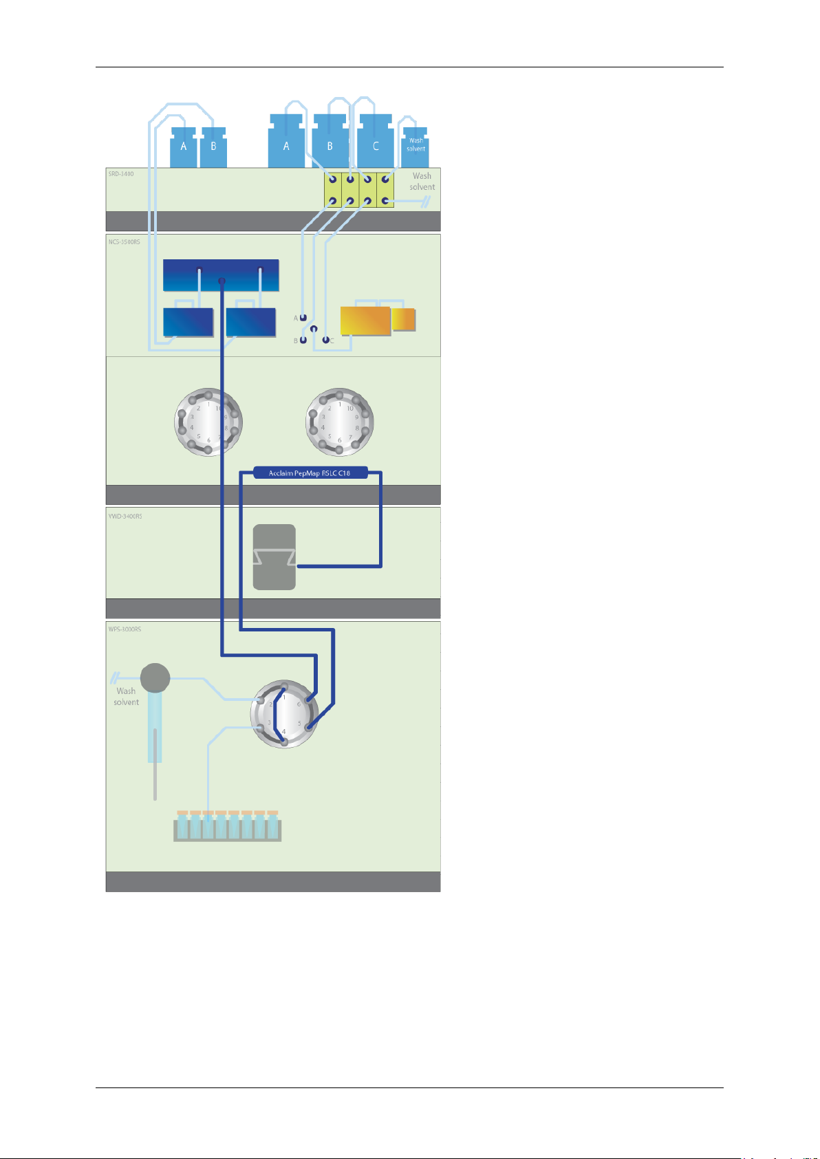
2.10.2 Fluidic Setup
Figure 27 presents the setup using the parts of the Automated Off-line Mic Nan SCX RP
application kit. Columns are marked with letters, tubing with digits.
Tip: The schematic shows 10-port switching valves, but this application can be
performed on 6-port valves. Ensure that the relative positions of the connections
are correct, and update the valve switching in the Chromeleon templates if
necessary.
Figure 27: Fluidic connections for an Automated Off-line 2D experiment
Table 8: UltiMate 3000 RSLCnano Automated Off-line SCX-RP peptides kit (P/N 6720.0330) contents
# Item Replacement P/N
1.0 mm I.D. x 15 cm, packed with Polysulfoethyl ASP, 5 µm, 300Å, nanoViper 164566
a
75 µm I.D. x 15 cm, packed with Acclaim PepMap RSLC C18, 2 µm, 100Å,
b
nanoViper
Nano Trap column, 75 µm I.D. x 2 cm, packed with Acclaim PepMap100 C18,
c
3 µm, 100Å (set of 2) nanoViper
nanoViper capillary FS/PEEK sheathed 1/32" I.D. x L 20 µm x 350 mm 6041.5240
1
nanoViper capillary FS/PEEK sheathed 1/32" I.D. x L 75 µm x 650 mm 6041.5775
2
nanoViper capillary FS/PEEK sheathed 1/32" I.D. x L 75 µm x 550 mm 6041.5760
3 (4)
nanoViper capillary FS/PEEK sheathed 1/32" I.D. x L 75 µm x 250 mm 6041.5730
5
164534
164535
39
Page 41

UltiMate 3000 RSLCnano – Standard Applications
Table 8: UltiMate 3000 RSLCnano Automated Off-line SCX-RP peptides kit (P/N 6720.0330) contents Continued
# Item Replacement P/N
nanoViper capillary FS/PEEK sheathed 1/32" I.D. x L 20 µm x 750 mm 6041.5280
nanoViper sample loop 50 µL, FS/PEEK sheathed I.D. x L 250 µm x 408 mm 6826.2450
6
PTFE tubing, 500 µm I.D. 100 cm, used as waste tubing 6720.0077
7
Protein mixture digest, 100 pmol, Lyophilized 161088
Cytochrome C digest, 1.6 nmol, Lyophilized 161089
Polypropylene vials for WPS with glass insert, 250 µL, 25 pcs. 6820.0027
Polypropylene caps for WPS vials, 25 pcs. 6820.0028
96 Well Microplate, PP, V-Bottom 6820.4113
1/16" Universal Fingertight Fitting, one-piece design, extra long thread, 4 pcs. 6720.0015
Buffer tubing 500 µL, WPS-3000PL 6820.0020
LCi Solutions Library CD 6830.0400
Operating Instructions for automated off-line 2D-LC of peptides and proteins 164208
2.10.3 Installation Tips
• Follow the General Recommendations for Applications (→ page 6).
• The design of the nano trap column provides the easiest connections, but must only be
used in forward flush operation. Please check the indicated flow direction when
installing a nano trap column.
• If the loss of hydrophilic peptides is observed, the concentration of acetonitrile in the
loading solvent can be decreased down to 99/1 water/ACN + 0.05% TFA
• If too much hydrophobic secondary interaction is observed on the IEX column, the
amount of ACN can be increased up to 5% or 10%.
• The loading time and desalting time are highly dependent on the sample quantity and
purity. They can be adjusted to meet customer needs. However, the desalting step must
be kept long enough to avoid the formation of adducts between salt and sample.
• Optimal trapping in the second dimension is achieved by adding a strong ion-pairing
agent to the fractions, prior to reinjection.
40
Page 42

UltiMate 3000 RSLCnano – Standard Applications
2.10.4 Testing the Application
The Mic Nan SCX – RP application setup can be tested using the following conditions:
Property Setting
Mobile phase A 100% water + 0.05% TFA
Mobile phase B 20%/80% (v/v) water/ACN + 0.04% TFA
Loading pump A 5 mM HxPO4 pH 3 + 5% ACN
Loading pump B Loading pump A with 1 M NaCl
Loading pump C 98%/2% (v/v) water/ACN + 0.05% TFA
Sample Protein mix digest, prepared according to the included instruction sheet
Injection volume Sample: 10 μL
Fractions: 20 μL
Gradient SCX 0-50% B in 20 min
90%B for 5 min
10 min equilibration
SCX flow rate 50 µL/min
UV detection 214 nm
Fractions Every minute for 20 minutes
Loading time 7 min (may vary with different injection volume/routine)
Desalting time 5 min (counted after loading time has passed)
Gradient RP Isocratic 4% for 10min
4% to 55% B in 30 min
90% B for 5 min
15 min equilibration
WPS temperature
Loading flow 5 μL/min
Flow rate 300 nL/min (nano flow selector)
5°C
The automated off-line application allows, as any off-line application, optimization of the
individual separation dimensions. Thermo Fisher Scientific recommends testing and
optimizing the performance of each separation dimension (SCX and RP) individually in a
one-dimensional application.
This means that, for a nano RP second dimension, the test criteria are identical as described in
the part of Pre-concentration onto a Nano Column on page 21.
41
Page 43

UltiMate 3000 RSLCnano – Standard Applications
2.11 Automated off-line 2D LC, Cap RP (basic) x nan RP (acidic)
2.11.1 Hardware Layout
Figure 28: Setup for an Automated Off-line 2D Cap Nan experiment
The recommend setup is presented in
Figure 28 and consists of:
SRD-3400 5035.9245
Tip: The µFC option limits
the upper pressure of the
first dimension to
350 bar, due to the
NCS-3500RS 5041.0010
applied 8-port valve.
NCP-3200RS 5041.0030
2x 10-port sw. valve 6041.0001
The NCP-3200RS spare
parts kit has two 130 cm
VWD-3400RS 5074.0010
3 nL flow cell 6074.0270
45 nL flow cell 6074.0280
WPS-3000PL 5820.0010
µFC option 6820.0051
long solvent inlet tubing
to place the bottles on
top of the system.
Application kit: 6720.0340
42
Page 44

UltiMate 3000 RSLCnano – Standard Applications
2.11.2 Fluidic Setup
Figure 29 presents the setup using the parts of the Automated Off-line Cap Nan application
kit. Columns are marked with letters, tubing with digits.
Tip: The schematic shows 10-port switching valves, but this application can be
performed on 6-port valves. Ensure that the relative positions of the connections
are correct, and update the valve switching in the Chromeleon templates if
necessary.
Figure 29: Fluidic connections for an Automated Off-line 2D experiment
Table 9: UltiMate 3000 RSLCnano Automated Off-line RP-RP peptides kit (P/N 6720.340) contents
# Item Replacement P/N
75 µm I.D. x 15 cm, packed with Acclaim PepMap RSLC C18, 2 µm, 100Å,
a
nanoViper
Nano Trap Column, 75 µm I.D. x 2 cm, packed with Acclaim PepMap100 C18,
b
3 µm, 100Å (set of 2) nanoViper
0.3 mm I.D. x 15 cm, packed with Acclaim PA2, nanoViper 164592
c
nanoViper capillary FS/PEEK sheathed 1/32" I.D. x L 20 µm x 350 mm 6041.5240
1
nanoViper capillary FS/PEEK sheathed 1/32" I.D. x L 50 µm x 350 mm 6041.5540
2
nanoViper capillary FS/PEEK sheathed 1/32" I.D. x L 50 µm x 650 mm 6041.5575
3
nanoViper outlet tubing 50 um I.D. x 30 cm 6041.4573
4
Nano connector including connection sleeves 6720.0390
nanoViper capillary FS/PEEK sheathed 1/32" I.D. x L 75 µm x 350 mm 6041.5735
5
164534
164535
nanoViper capillary FS/PEEK sheathed 1/32" I.D. x L 75 µm x 250 mm 6041.5730
6
nanoViper capillary FS/PEEK sheathed 1/32" I.D. x L 20 µm x 750 mm 6041.5280
nanoViper sample loop 20 µL, FS/PEEK sheathed I.D. x L 250 µm x 408 mm 6826.2420
43
Page 45

UltiMate 3000 RSLCnano – Standard Applications
100% water, 1% (72 mM) triethylamine (TEA) titrated to pH = 9.6 with acetic
19%/80% (v/v) water/ACN, 1% (72 mM) triethylamine (TEA), titrated to pH =
Table 9: UltiMate 3000 RSLCnano Automated Off-line RP-RP peptides kit (P/N 6720.340) contents - Continued
# Item Replacement P/N
PTFE tubing, 500 µm I.D. 100 cm, used as waste tubing 6720.0077
1/16" Universal Fingertight Fitting, one-piece design, extra long thread, 4 pcs. 6720.0015
Protein mixture digest, 100 pmol, Lyophilized 161088
Cytochrome C digest, 1.6 nmol, Lyophilized 161089
Polypropylene vials for WPS with glass insert, 250 µL, 25 pcs. 6820.0027
Polypropylene caps for WPS vials, 25 pcs. 6820.0028
96 Well Microplate, PP, V-Bottom 6820.4113
LCi Solutions Library CD 6830.0400
Operating Instructions for automated off-line 2D-LC of peptides and proteins 164208
2.11.3 Installation tips
• Follow the General Recommendations for Applications (→ page 6).
• The design of the nano trap column provides the easiest connections, but must only be
used in forward flush operation. Please check the indicated flow direction when
installing a nano trap column.
• If the loss of hydrophilic peptides is observed, the concentration of acetonitrile in the
loading solvent can be decreased down to 99/1 water/ACN + 0.05% TFA.
• Optimal trapping in the second dimension is achieved by adding a strong, acidic ion-
pairing agent to the fractions and a combination of evaporating and diluting the ACN
from the first dimension.
• When two VWD-3400RS detectors are available, they should be placed on top of each
other.
• Depending on the location of the MS outlet and the application of UV detection (1st or
2nd Dimension), the WPS can be placed on the left side of the system.
2.11.4 Testing the application
The automated off-line application allows, as any off-line application, optimization of the
individual separation dimensions. Thermo Fisher Scientific recommends testing and
optimizing the performance of each separation dimension (RP basic and RP acidic)
individually in a one-dimensional application.
This means that the test criteria for a nano RP second dimension are identical as described in
the part of Pre-concentration onto a Nano Column on page 21.
Property Setting
NCS NC_Pump A
NCS NC_Pump B
Loading pump A 98%/2% (v/v) water/ACN + 0.05% TFA
NCP NC_Pump A 100% water + 0.05% TFA
NCP NC_Pump B 20%/80% (v/v) water/ACN + 0.04% TFA
acid
9.6 with
acetic acid
44
Page 46

UltiMate 3000 RSLCnano – Standard Applications
Property Setting
Sample Protein mix digest, prepared according to the included instruction sheet
Injection volume Sample: 10 μL
Fractions: 20 μL
Gradient RP basic 4-60% B in 15 min,
90% B for 5 min,
25 min equilibration
UV detection 214 nm
Fractions Every minute for 20 minutes
Loading time 7 min (may vary with different injection volume/routine)
Gradient RP acidic Isocratic 4% for 10min
4% to 55% B in 30 min
90% B for 5 min
15 min equilibration
WPS temperature
Flow rate cap 6 µL/min
Loading flow 5 μL/min
Flow rate nano 300 nL/min
5°C
45
Page 47

2.12 Tandem nano LC
2.12.1 Hardware Layout
UltiMate 3000 RSLCnano – Standard Applications
Figure 30: Setup for a Tandem nano LC experiment
The recommended setup is presented in Figure 30
and consists of:
SRD-3400 5035.9245
NCS-3500RS 5041.0010
NCP-3200RS 5041.0030
2x 10-port sw.valve 6041.0001
VWD-3400RS 5074.0010
3 nL flow cell 6074.0270
WPS-3000FC 5824.0020
Application kit: 6720.0335
Tip: The components to
convert the WPS3000FC are included in
the application kit.
The NCP-3200RS spare
parts kit has two 130 cm
long solvent inlet tubing
to place the bottles on
top of the system.
46
Page 48

UltiMate 3000 RSLCnano – Standard Applications
2.12.2 Fluidic Setup
Figure 31 presents the setup using the parts of the Tandem nano LC application kit. Columns
are marked with letters, tubing with digits.
Tip: The schematic shows 10-port switching valves, but this application can be
performed on 6-port valves. Ensure that the relative positions of the connections
are correct, and update the valve switching in the Chromeleon templates if
necessary.
Figure 31: Fluidic connections for a Tandem nano LC experiment
A field upgrade to the WPS-3000FC needs to be performed to make the autosampler suitable
for this application. First, the nano injection kit (P/N 6824.0030) should be installed and
secondly the lower valve must be replaced with the nano switching valve (P/N 6825.0020).
All necessary parts are included in the kit. For further information, refer to the operating
instructions for the module.
Table 10: UltiMate 3000 RSLCnano Tandem nano LC kit (P/N 6720.0335) contents
#
Item Replacement P/N
75 µm I.D. x 15 cm, packed with Acclaim PepMap RSLC C18, 2 µm, 100Å,
a
nanoViper
Nano Trap Column, 75 µm I.D. x 2 cm, packed with Acclaim PepMap100 C18,
b
3 µm, 100Å (set of 2) nanoViper
nanoViper capillary FS/PEEK sheathed 1/32" I.D. x L 20 µm x 350 mm 6041.5240
1
nanoViper capillary FS/PEEK sheathed 1/32" I.D. x L 75 µm x 650 mm 6041.5775
2,3
nanoViper capillary FS/PEEK sheathed 1/32" I.D. x L 75 µm x 250 mm 6041.5730
4
nanoViper capillary FS/PEEK sheathed 1/32" I.D. x L 20 µm x 750 mm 6041.5280
164534
164535
PTFE tubing, 500 µm I.D. 100 cm, used as waste tubing 6720.0077
5
nanoViper sample loop 20 µL, FS/PEEK sheathed I.D. x L 250 µm x 408 mm 6826.2420
Fused silica tubing I.D. 20µm O.D. 280µm, 5 meters for nano LC connections 160475
47
Page 49

UltiMate 3000 RSLCnano – Standard Applications
Table 10: UltiMate 3000 RSLCnano Tandem nano LC kit (P/N 6720.0335) contents - Continued
#
Item Replacement P/N
Cleaving stone 160483
Upgrade kit nano/cap WPS-3000TFC 6824.0030
1/32” 2 pos 6 port nano switching valve 6825.0020
Fittings for nano valve 6720.0080
Polypropylene vials for WPS with glass insert, 250 µL, 25 pcs. 6820.0027
Polypropylene caps for WPS vials, 25 pcs. 6820.0028
Cytochrome C digest, 1.6 nmol, Lyophilized 161089
1/16" Universal Fingertight Fitting, one-piece design, extra long thread, 4 pcs. 6720.0015
2.12.3 Installation Tips
• Follow the General Recommendations for Applications (→ page 6).
• The standard column outlets are 30 cm fused silica capillaries. 20 µm I.D. fused silica
tubing is provided in the kit to extend the column outlets if necessary. Replacing the
attached fused silica by the appropriate length using the nano connector on the column
will give the best result.
• The design of the nano trap column provides the easiest connections, but must only be
used in forward flush operation. Please check the indicated flow direction when
installing a nano trap column.
• If the loss of hydrophilic peptides is observed, the concentration of acetonitrile in the
loading solvent can be decreased down to 99/1 water/ACN + 0.05% TFA
• The WPS-3000FC is normally used for fraction collection. By replacing the divert valve
by a nano valve, the autosampler is fitted for tandem nano LC. Controlling the divert
valve position is performed with the commands Collect and Drain.
2.12.4 Testing the Application
The tandem nano LC setup consists of two pre-concentration nano setups that can be operated
individually; therefore, the system can be tested and evaluated using the conditions in the
table below, as also described in the part of Pre-concentration onto a Nano Column on page
21.
Property Setting
Mobile phase A 100% water + 0.05% TFA
Mobile phase B 20%/80% (v/v) water/ACN + 0.04% TFA
Loading pump A 98%/2% (v/v) water/ACN + 0.05% TFA
Sample Cytochrome C 1 pmol/µL, prepared according to instruction sheet
Injection volume Sample: 1 μL
UV detection 214 nm
Loading time 3 min (may vary with different injection volume/routine)
48
Page 50

UltiMate 3000 RSLCnano – Standard Applications
Property Setting
Gradient RP 4% to 55% B in 30 min
90% B for 5 min
15 min equilibration
WPS temperature
Loading flow 5 μL/min
Flow rate 300 nL/min (nano flow selector)
5°C
49
Page 51

UltiMate 3000 RSLCnano – Standard Applications
3 FAQ
3.1 Interpreting a Chromatogram
A typical Cytochrome C separation is shown in Figure 32. The different areas of a
chromatographic separation are marked inside the figure.
Figure 32: Example Cytochrome C separation with different parts of the run identified.
The finite volume of an HPLC system requires a certain time between the formation of a
gradient and detecting the gradient change. This so-called gradient delay can be seen by
comparing the programmed gradient with the detected signal. Figure 32 shows the gradient
delay between pump and UV detector.
The ‘inject peak’ really corresponds to the inject peak in direct injection setups, in preconcentration setups a similar baseline can be observed, but then the area marked as inject
peak resembles the trapping column being placed in line with the nano column.
The dwell volume represents the volume between the autosampler and the nano columns,
since there are usually one (direct injection) or two (pre-concentration) valve switches
involved in the application, which introduce addition fluidics, the dwell volume and gradient
delay are not the same volume.
3.2 Troubleshooting nano LC peptide Applications
The above chromatogram Figure 32 shows the separation of a Cytochrome C digest on a nano
column. The Cytochrome C standard appears relatively simple compared to a typical
proteomics sample, but is ideal for troubleshooting a direct injection and pre-concentration
setup.
Tip: When troubleshooting a pre-concentration setup, Thermo Fisher Scientific
recommends switching back to direct injection if the tips below do not provide
remedy.
In assessing the separation performance of a system several points are evaluated, which are
organized in the flow chart below. The values in the flowchart are based on a Cytochrome C
digest separation; when working with a different standard use a reference chromatogram for
the expected values for number of peaks, intensity and elution window.
50
Page 52

UltiMate 3000 RSLCnano – Standard Applications
51
Page 53

UltiMate 3000 RSLCnano – Standard Applications
3.3 The use of TFA and FA
The separation of peptides by reversed phase is typically done in the presence of an ion
pairing agent. The typical ion pairing agents serve a double function. First, these weak acids
bring the pH of the solvents down to pH 2-3, causing almost all peptides to have an overall
positive charge. Secondly, the negative counterion of the acid will serve as the ion pairing
agent with the peptides to create an overall neutral analyte that is separates on the RP column.
The double function of the ion pairing agent allows having an efficient separation with
minimal additives added to the solvents. Nonetheless, there is a choice of ion pairing agents,
where the most common choice is between Trifluoro Acetic Acid (TFA) and Formic Acid
(FA). In this manual, TFA is used in the application as this is the stronger ion pairing agent
and results in better chromatography. However, in LC-MS applications, often FA is preferred
to minimize the effects of ion suppression. When performing the applications mentioned in
this manual with FA, replace the volume (%) of TFA by double the volume (%) of FA; e.g.
0.05% TFA becomes 0.1% FA.
3.4 Minimizing Baseline Noise
The 3 nL flow cell (P/N 6074.0270) and 45 nL flow cell (P/N 6074.0280) are designed to
function in the same way as transfer tubing normally used to connect a column outlet to a
mass spectrometer. This allows UV detection in nano and capillary LC without introducing
post column band broadening.
Typically peptide UV detection is performed at a wavelength of 214 nm, in which most
organic compounds absorb quite strongly. There are some actions that can be taken to
minimize baseline drift and noise for optimal use of the UV detection.
3.4.1 Drift
Ensure that the UV lamp has been switched on for sufficient time in order to have it running
at a stable temperature. Chromeleon can detect this and will give a warning during the ‘Ready
Check‘ if the UV lamp temperature is not stable yet. The UV detector can be used, but it is
not at its optimal performance.
Gradient RP nano LC typically involves a significant change in solvent composition. The
higher absorption from the organic modifier in the B solvent will result in a rise of the
baseline. The ion pairing agent (typically FA or TFA) in the A and B solvent can be used to
compensate the baseline rise. As a rule of thumb, the compositions as indicated in Table 11
can be used to obtain a straight baseline.
Table 11: Ion pairing agent addition
A B
FA 0.1% 0.08%
TFA 0.05% 0.04%
Lamp and flow cell age can have a significant influence on baseline drift. New lamps and
flow cells may show some drift during the so-called ‘burn in’ period.
Lamps should be replaced after approximately 2000 hours and older flow cells can be cleaned
by flushing overnight with organic solvent or for a shorter period with a strong acidic
solution; see operating instructions for details.
52
Page 54

UltiMate 3000 RSLCnano – Standard Applications
3.4.2 Unstable Baseline
Unstable baselines can have various causes. The UltiMate 3000 RSLCnano pumps are
designed to provide the best gradient precision, but solvent miscibility can present a problem.
Therefore, Thermo Fisher Scientific recommends using a minimum of 5% water in the
organic mobile phase.
Baseline artifacts in pre-concentration applications using low loading flows (< 10 µL/min)
may occur. These artifacts are only observed in the UV signal and have no effect on the
performance of the analysis. If artifacts in the baseline are observed, Thermo Fisher Scientific
recommends bypassing the degasser in pre-concentration applications where no gradient
formation is required and loading flows are below 20 µL/min. If bypassing the degasser is
undesired or impossible an alternative is to maintain degassing, but to increase the loading
flow during the elution phase to values between 30 and 100 µL/min.
53
Page 55

UltiMate 3000 RSLCnano – Standard Applications
PEEK Tubing
Nut
Ferrule
Injection Port/Union
Fused Silica Capillary
PTFE Connec t or
4 Appendix – Traditional Capillary Connections
• When installing fused silica tubing (for example, the capillary column):
o Insert the PEEK sleeve with the stainless steel nut (standard) or PEEK nut
(biocompatible system) and the appropriate ferrule in a port (or the preassembly
tool, when working on a biocompatible system!).
o Push the sleeve all the way into the port. It is essential for a zero dead volume
connection that the assembly seats firmly.
o Tighten the nut by two or three turns to make certain that the ferrule grabs the
sleeve.
o Remove the pre-assembled fitting, and then slide the capillary (column) into the
sleeve.
o When re-installing the fitting together with the capillary (column), make certain
that the tip of the tubing does not extend the tip of the sleeve. Tighten the nut
finger-tight.
o Push the capillary (column) all the way into the sleeve (port) to minimize dead
volume. It is essential for a zero dead volume connection that the assembly seats
firmly.
• To prepare connections with PTFE sleeves:
o Start flow delivery.
o Slide the fused silica capillary (for example, the column) approximately 1- 2 mm
into the sleeve.
o Wait until a droplet is formed at the outlet. Remove the droplet (together with
potential dirt in the tubing).
o Now push the capillary (column) half-way into the sleeve. Wait again until a
droplet is formed and remove it.
o Connect the second capillary (for example, the inlet capillary of the flow cell).
54
Page 56

UltiMate 3000 RSLCnano – Standard Applications
PEEK Sleeve (o range)
Nut
Fused Silica Capillary
280 ∝m O.D.
Microt ight
Union
Gauge Plug
• When using a micro tight union, always use the gauge plug provided with the union to
make sure that the connection is well centered.
55
Page 57

UltiMate 3000 RSLCnano – Standard Applications
164567
164568
164569
164570
164571
164572
164561
164562
164563
164534
164536
164540
164560
164537
164564
164535
164584
164543
164557
164542
164585
164586
164558
5 Appendix – Common Spare Parts in nano LC
The three tables below list the most common parts to be used with the UltiMate 3000
RSLCnano system. They are divided by columns (Table 12), tubing (Table 13, Table 14), and
hardware (Table 15).
Table 12: List of columns available for the UltiMate 3000 RSLCnano system
Item P/N
Acclaim PepMap Columns
Acclaim PepMap100, C18, 3 μm, 100 Å, 75 μm I.D. × 5 cm, nanoViper
Acclaim PepMap100, C18, 3 μm, 100 Å, 75 μm I.D. × 15 cm, nanoViper
Acclaim PepMap100, C18, 3 μm, 100 Å, 75 μm I.D. × 25 cm, nanoViper
Acclaim PepMap100, C18, 3 μm, 100 Å, 75 μm I.D. × 50 cm, nanoViper
Acclaim PepMap100, C18, 3 μm, 100 Å, 300 μm I.D. × 15 cm, nanoViper
Acclaim PepMap100, C18, 3 μm, 100 Å, 1 mm I.D. × 15 cm, nanoViper
Acclaim PepMap RSLC Columns
Acclaim PepMap RSLC C18, 2 μm, 100 Å, 50 μm I.D. x 5 cm, nanoViper
Acclaim PepMap RSLC C18, 2 μm, 100 Å, 50 μm I.D. x 15 cm, nanoViper
Acclaim PepMap RSLC C18, 2 μm, 100 Å, 75 μm I.D. x 5 cm, nanoViper
Acclaim PepMap RSLC C18, 2 μm, 100 Å, 75 μm I.D. x 15 cm, nanoViper
Acclaim PepMap RSLC C18, 2 μm, 100 Å, 75 μm I.D. x 25 cm, nanoViper
Acclaim PepMap RSLC C18, 2 μm, 100 Å, 75 μm I.D. x 50 cm, nanoViper
Acclaim PepMap RSLC C18, 2 μm, 100 Å, 300 μm I.D. x 5 cm, nanoViper
Acclaim PepMap RSLC C18, 2 μm, 100 Å, 300 μm I.D. x 15 cm, nanoViper
Nano Trap Columns
Nano Trap Column, 100 μm I.D. x 2 cm, packed with Acclaim PepMap100 C18, 5 μm
Nano Trap Column, 75 μm I.D. x 2 cm, packed with Acclaim PepMap100 C18, 3 μm
Cartridge based trap columns.
μ-Precolumn™ holder, 5 mm, with 30 μm i.d. connecting tubing, nanoViper fittings 164649
300 µm i.d. x 5 mm, packed with Acclaim PepMap100 C18, 5 µm, 100Å (set of 5 cartridges) 160454
PepSwift and ProSwift Monolithic Columns
PepSwift Monolithic Nano Column, 100 μm I.D. × 5 cm, nanoViper
PepSwift Monolithic Nano Column, 100 μm I.D. x 25 cm, nanoViper
PepSwift Monolithic Capillary Column, 200 μm I.D. x 5 cm, nanoViper
PepSwift Monolithic Capillary Column, 200 μm I.D. x 25 cm, nanoViper
PepSwift Monolithic Capillary Column, 500 μm I.D. × 5 cm, nanoViper
ProSwift RP-10R Monolithic Capillary Column, 1 mm I.D. × 5 cm, nanoViper
PepSwift Trap Columns
PepSwift Monolithic Trap Column, 200 μm x 5 mm, set of 2, nanoViper
56
Page 58

UltiMate 3000 RSLCnano – Standard Applications
Table 13: Matrix for connection tubing for the UltiMate 3000 RSLCnano system
ID
Length (mm)
70 6041.5120 6041.5123 6041.5126 6041.5810 6041.5817
150 6041.5121 6041.5124 6041.5127 6041.5811 6041.5818
250 - - 6041.5730 6041.5812 6041.5819
350 6041.5240 6041.5540 6041.5735 6041.5813 6041.5820
450 - - - 6041.5814 6041.5821
550 6041.5260 6041.5560 6041.5760 6041.5815 6041.5822
650 6041.5275 6041.5575 6041.5775 - -
750 6041.5280 6041.5580 6041.5780 6041.5816 6041.5823
950 6041.5122 6041.5125 6041.5128 - -
Table 14: List of connection tubing for the UltiMate 3000 RSLCnano system
Item P/N
Sample loops
20 µm
[Orange]
50 µm
[Brown]
[Color code]
75 µm
[Black]
100 µm
[Red]
150 µm
[Purple]
Sample loop 1 μL with nanoViper fittings connections 6826.2401
Sample loop 5 μL with nanoViper fittings connections 6826.2405
Sample loop 20 μL with nanoViper fittings connections 6826.2420
Sample loop 50 μL with nanoViper fittings connections 6826.2450
Connectors
Nano connector including connection sleeves 6720.0390
Sleeve for Nano Connector, 5 pcs. 6720.0391
PTFE tubing, 250 µm I.D., for low pressure connection of 280 µm O.D. FS. capillaries,
5 pcs.
Microtight Union including 2 fittings and 1 gauge plug 161497
PEEK sleeves, precision cut and polished for connections with Microtight Union (280 µm
O.D.), 10 pieces
PEEK sleeves, precision cut and polished for connections with Microtight Union (380 µm
O.D.), 10 pieces
160486
161498
161405
57
Page 59

UltiMate 3000 RSLCnano – Standard Applications
Table 15: List of hardware components for the UltiMate 3000 RSLCnano system
Item P/N
Low dispersion 2 pos 10 port valve high pressure for NCS-3x00 6041.0001
Low dispersion 2 pos 6 port valve high pressure for NCS-3x00 6041.0004
Low-dispersion 2 pos 10 port valve, PAEK, bio, NCS-3x00 6041.0012
Viper blind plug 6040.2303
Flow selector nano LC 6041.0002
Flow selector capillary LC 6041.0003
Flow selector micro LC 6041.0014
Mixer kit 8 µL NCS/NCP 6041.7130
NCS/NCP purge capillary 6040.2385
58
 Loading...