

Page 1
Fluorescence Detector
RF-2000
Operating Instructions
Version: 1.40
Datum: July 7, 2000
© 2000 Dionex Softron GmbH
Doc.: RF2000_OI_E_V140.doc
Page 2

Operating Instructions RF-2000
DECLARATION OF CONFORMITY
We, Dionex Softron GmbH, declare that the product Fluorescence Detector
RF-2000
to which this declaration relates, is in conformity with the following European standards:
# EN 50081-1 (1992):
# EN 50082-1 (1992):
Attention
January 27, 1998 QM-Manager
Dionex Softron will not accept any liability for damage, direct or indirect,
caused by connecting this instrument to devices which do not meet relevant
safety standards.
Electromagnetic compatibility - Generic emission standard
Part 1: Residential, commercial and light industry
Electromagnetic compatibility - Generic immunity standard
Part 1: Residential, commercial and light industry
Page 3

Operating Instructions RF-2000
CONTENTS
1 Precautions ................................................................................................3
1.1 Warnings in these Operating Instructions ................................................................ 3
1.2 Warning Labels on the Unit ..................................................................................... 3
1.3 Replacement of Fuses............................................................................................. 5
1.4 Precautions on Installation Site and Handling of the Unit......................................... 6
1.5 Precaution in the region where 240V is used as working voltage............................. 7
1.6 Precautions on Static Electricity............................................................................... 8
2 General Information................................................................................. 11
2.1 Outline................................................................................................................... 11
2.2 Features................................................................................................................ 11
3 Component Location and Function .......................................................12
3.1 Front View............................................................................................................. 12
3.2 Top Side and Right Side........................................................................................ 13
3.3 Bottom Side........................................................................................................... 13
3.4 Rear View.............................................................................................................. 14
4 Installation ................................................................................................15
4.1 Basic Installation Requirements............................................................................. 15
4.2 Electrical Connections........................................................................................... 16
4.3 Fluidic Connections ............................................................................................... 17
4.4 Connecting the Recorder and the Integrator.......................................................... 18
4.5 Connecting a Drain Tube for Solvent Leakage ...................................................... 19
4.6 Installing the Xenon Lamp ..................................................................................... 19
4.7 Adjusting the Xenon Lamp Alignment.................................................................... 23
5 Operation ..................................................................................................26
5.1 Precautions for Operation...................................................................................... 26
5.2 Fundamentals of Operation ................................................................................... 26
5.3 Operating Procedure in Spectrum Scanning Mode ................................................ 33
5.4 Creating and Executing a Time Program ............................................................... 36
5.5 Additional Functions .............................................................................................. 42
6 Performance Verification ........................................................................ 50
6.1 Outline of System Validation.................................................................................. 51
6.2 Repeatability Test of Chromatographic Data (Isocratic LC) ................................... 51
6.3 Repeatability Test of Chromatographic Data (Gradient LC) ................................... 53
7 Control from External Equipment ..........................................................56
7.1 Connecting External Input and Output Terminals................................................... 56
7.2 Control from External Equipment via RS-232C...................................................... 58
i
Page 4

Operating Instructions RF-2000
8 Maintenance ............................................................................................. 64
8.1 Maintenance of Flow Cell ...................................................................................... 64
8.2 Checking the Xenon Lamp .................................................................................... 70
8.3 Replacing the Fuse................................................................................................ 72
8.4 Changing the Set Power Supply Voltage ............................................................... 73
8.5 Periodical Cleaning................................................................................................ 74
9 Troubleshooting ...................................................................................... 75
9.1 Summary of the Most Frequently Problems ........................................................... 75
9.2 List of Error Messages........................................................................................... 80
10 Specifications ....................................................................................... 84
11 Standard Accessories ..........................................................................86
12 Replacement Parts ...............................................................................86
ii
Page 5
Operating Instructions RF-2000
1 Precautions
The Dionex RF-2000 is the fluorescence detector for the high performance liquid
chromatograph. In order to operate the unit safely, strictly observe the following
points. It is dangerous not to comply with the following points.
• Use the unit for any purpose mentioned above.
• Follow the procedures described in the operating instructions.
• Observe the warnings and cautions.
• Do not disassemble or modify the unit without approval from Dionex. Failing to do
so may lead to a dangerous situation or damage to the instrument.
• For internal repair of the product, contact the Dionex Service .
1.1 Warnings in these Operating Instructions
Warning:
Important:
Please note:
Indicates that failure to take note of the accompanying
information may result in personal injury.
Indicates that failure to take note of the accompanying
information may cause wrong results or damage to the instrument
Indicates General information to assist you in obtaining optimum
performance.
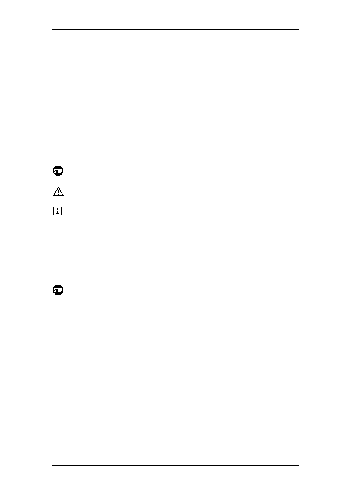
1.2 Warning Labels on the Unit
For safety of operation, this unit is provided with the mark at the portion where
special cautions are required. When operating the parts where this mark is indicated,
exercise special caution after reading the operating instructions.
Warning:
• The xenon lamp may explode in the course of long use (more than 1000hours).
Replace the lamp of expired life (500 hours) with a new one.
• Be sure to wear protective gears, such as protective mask, heavy and longsleeved shirt and gloves, when handling the xenon lamp. Since high pressure gas
is charged in the xenon lamp, if the lamp is strongly shocked or the glass surface
is scratched, the lamp may explode and pieces of glass may scatter.
• When mounting or replacing the xenon lamp, be sure to turn OFF the power
switch and disconnect the power cable. Voltage is applied to the electrode by the
electric charge right after the power switch is turned OFF. Therefore, leave the
xenon lamp for more than five minutes after turning the power switch OFF before
opening the cover of the light source chamber.
• The xenon lamp is very hot when it is lit. Therefore, when replacing the xenon
lamp, wait for more than an hour after turning the power OFF to cool the lamp
enough for replacement.
• High voltage (approx. 30 kV) is applied to the xenon lamp during ignition. When
turning ON the power, be sure to mount the lamp and close the cover of the light
source chamber.
3
Page 6
Important:
Be sure to read this instruction manual before supplying power to this unit.
• Be sure to mount the xenon lamp correctly before supplying the power to this unit
(refer to 4.7 Installing the Xenon Lamp). Failing to do so may damage the main
unit because high voltage around 30kV is applied to electrode when turning ON
the xenon lamp.
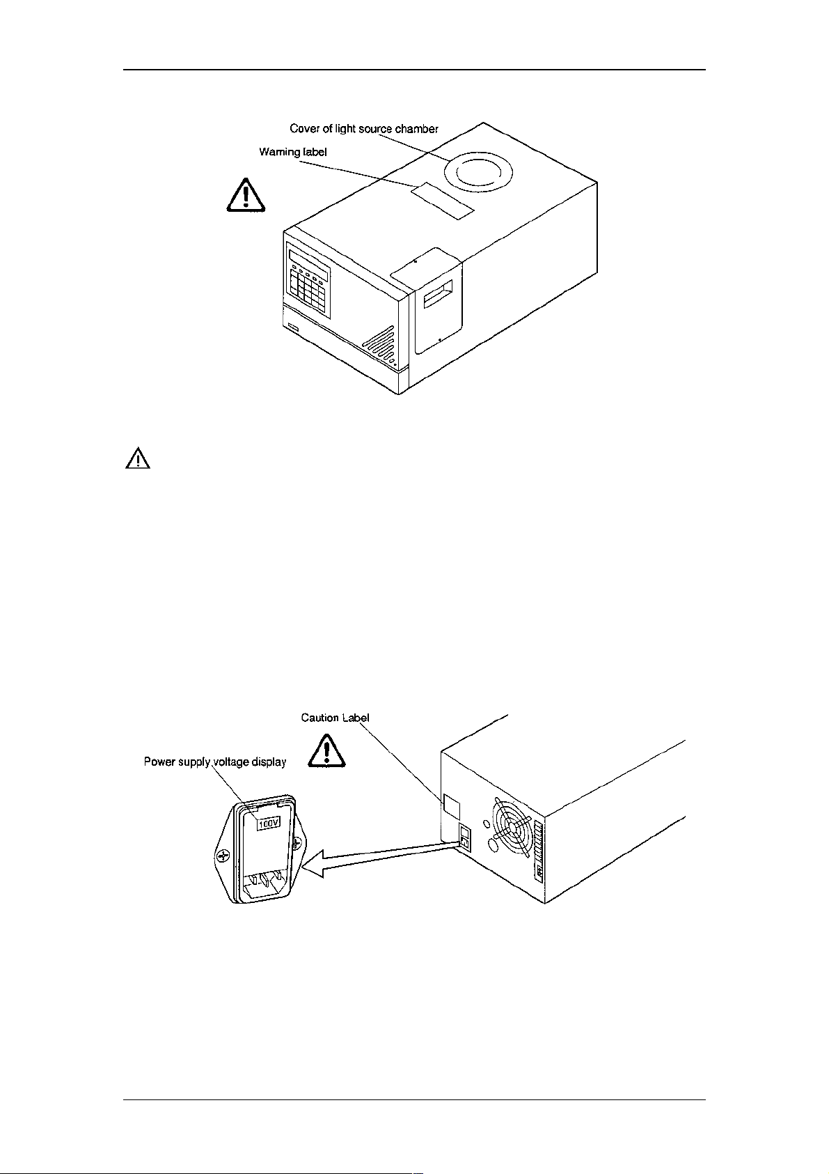
• Use the power supply voltage at the state which conforms to the power supply
setting (display of the power supply connector unit at the rear) of this unit. For
changing the power supply setting of this unit, refer to 8.4 Changing the Set Power
Supply Voltage. However, when the voltage is 220V ± 10%, set the power supply
voltage of this unit at 230Vac.
Operating Instructions RF-2000
4
Page 7
Operating Instructions RF-2000
1.3 Replacement of Fuses
This unit uses the following fuse. Be sure to replace the fuse of the same type and
capacity.
Power supply voltage: 220-240 V
Part no. 706.072.0165221
250V 3.15AT
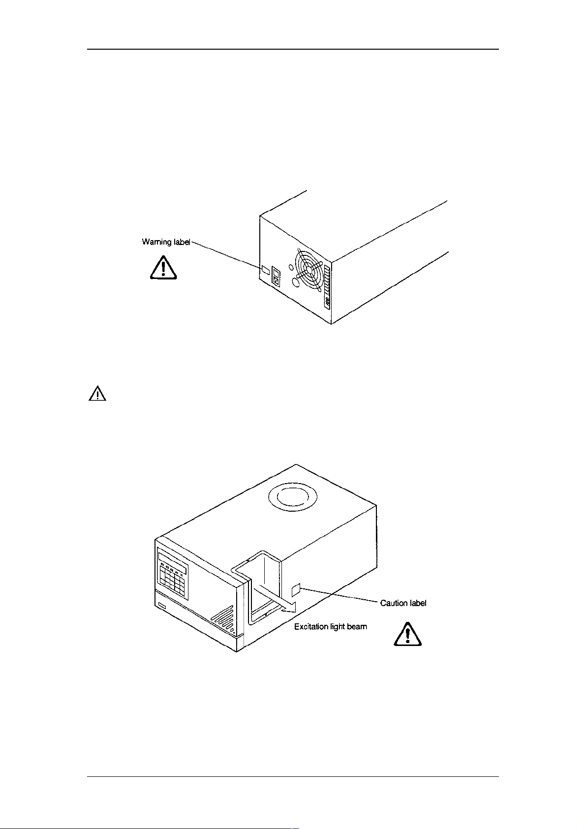
Important:
When the xenon lamp is lit, the flow cell is irradiated by the
excitation light beam. Do not look into the excitation light beam,
while the xenon lamp is lit.
5
Page 8

Operating Instructions RF-2000
1.4 Precautions on Installation Site and Handling of the Unit
Generally, a large amount of organic solvents is used in the high-performance liquid
chromatograph. Sufficient care should be taken in installation site and handling of the
unit. Please take care of the notices in the text, not to mention the precautionary
requirements listed below:
1.4.1 Ventilation
Solvents used in the high-performance liquid chromatograph are inflammable
and/or toxic. Be sure to ventilate the room well.
1.4.2 Fire
The lighting of fires is prohibited in the room where high-performance liquid
chromatograph is installed. Do not install any devices which may emit sparks
in the room. It is also necessary to provide a fire extinguisher preparing for the
worst.
1.4.3 Safety goggles
Wear safety goggles in handling solvents.
1.4.4 Other equipment
A washstand or the like is necessary to be furnished nearby preparing for the
cases such that solvent comes into the personnel's eyes or the personnel
touches toxic solvent.
1.4.5 Power source
Working voltage range and power consumption of this system are as follows.
Be sure to connect to the power source conforming to them.
Part No. 706.228.35353.38, 220-230V ~ ±10%/240V ~ ±10%, 350VA,
50-60Hz
If working with a different working range, different fuses must be used! Please
contact the Dionex Service.
1.4.6 Grounding
To prevent electric shock and to secure safe operation of the system, always
make grounding.
1.4.7 Repair and maintenance of the unit
Normal maintenance of this unit can be performed without removing the
cover. Do not remove the cover at the normal maintenance. Contact the
Dionex Service if repair requires to remove the cover of the main body.
6
Page 9
Operating Instructions RF-2000
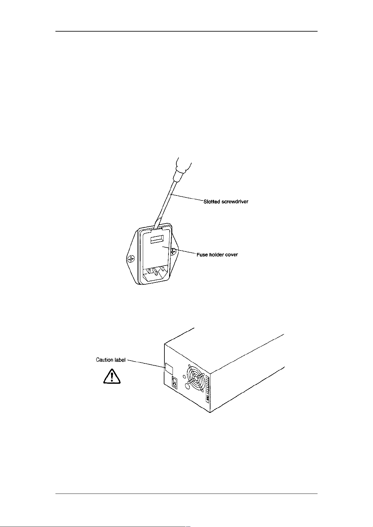
1.5 Precaution in the region where 240V is used as working
voltage
1.5.1 Confirming the working voltage
The voltage setting must correspond to the working voltage used. When the working
voltage is between 220V and 230V, it is not necessary to change the factory setting
(230Vac). However, when the working voltage is 240V, change the voltage setting as
follows:
(1) Turn OFF the power switch.
(2) Pull out the power supply cable from the power supply connector.
(3) Open the fuse holder cover at the rear of this unit by a slotted screwdriver.
(4) Change the rotary switch showing the voltage in the fuse holder to display
240Vac.
(5) Close the fuse holder cover until a clicking sound is heard.
7
Page 10
Operating Instructions RF-2000
1.6 Precautions on Static Electricity
Liquid chromatography using flammable organic solvents as mobile phase requires
proper care against fire, explosion, etc. Particularly, among various possible
accidents, those caused by static electricity are difficult to anticipate, and tend to
occur only with unexpected conditions which often make countermeasures
insufficient. At a site where preparative liquid chromatography is practiced, a large
amount of flammable substances may be used. Therefore, once an accident
happens, it could lead to tremendous damage. The mechanism of accident caused
by static electrical discharge and preventive measures are described below. Take
due care in safety measures in handling of equipment.
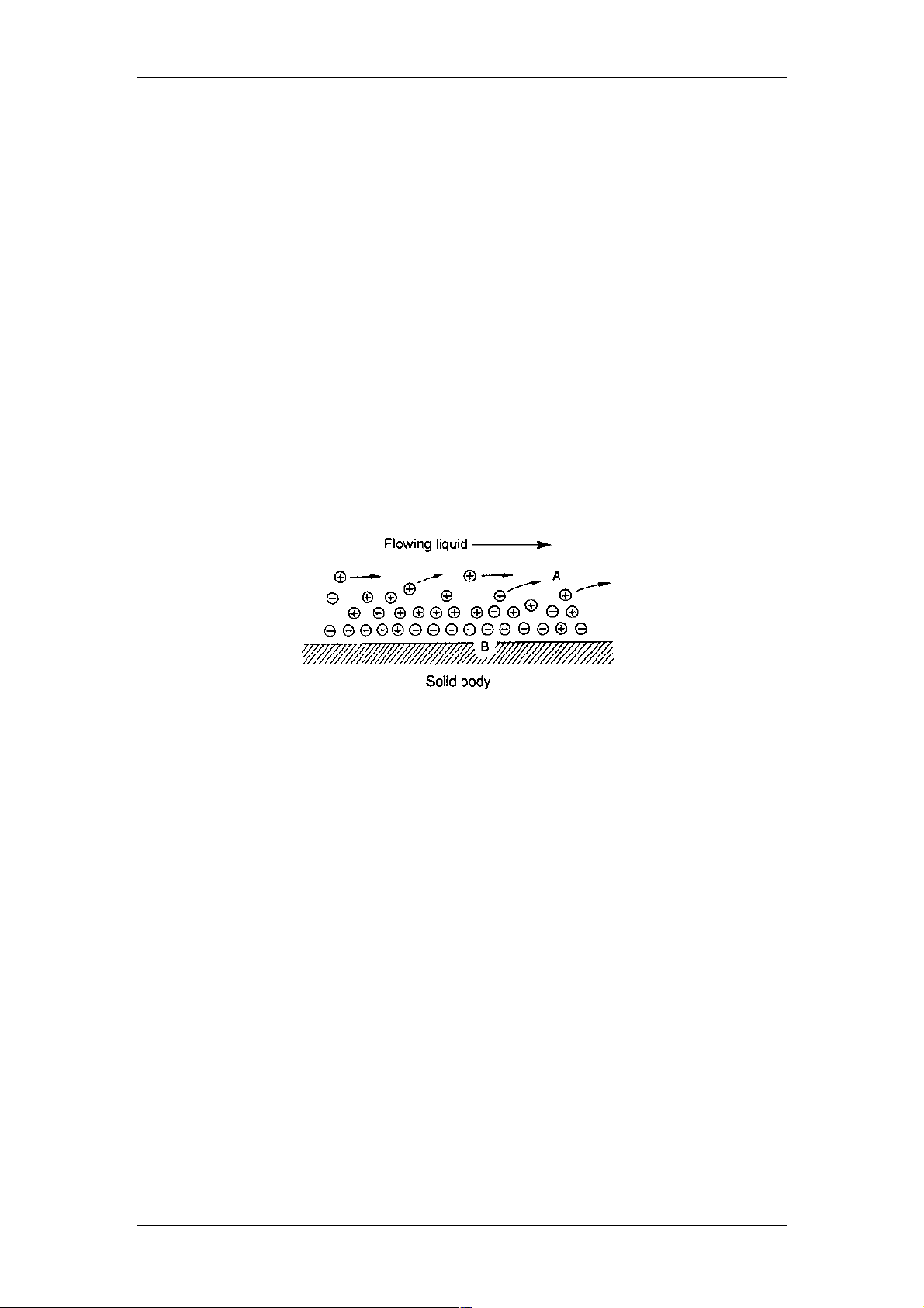
1.6.1 Mechanism of Static Electrical Discharge Accident (Example)
Accidents caused by static electricity take place through the following processes.
When liquid is fed at high speed through a small-diameter tube like the pipe of a
liquid chromatograph, static electrical charge occurs by friction between solid and
liquid as shown in the figure below
Fig.: Occurrence of Static Electricity by Friction between Solid and Liquid
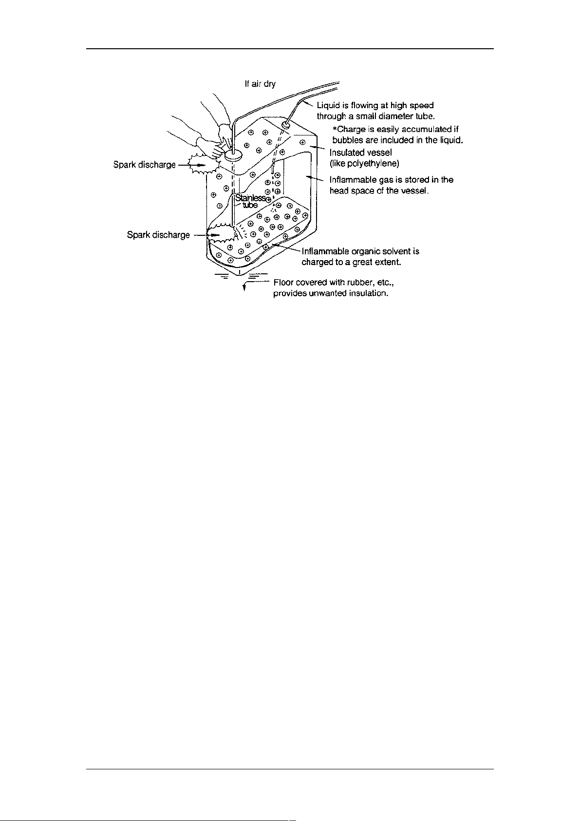
When the charged liquid is collected in an insulated vessel, the static charge
accumulates gradually, and the voltage can easily reach a few kilovolts. If some other
conductive object is brought near the vessel, electricity is discharged at a certain
distance from the vessel releasing heat energy. If flammable gas of sufficient
concentration exists nearby, ignition is caused by this energy.
8
Page 11
Operating Instructions RF-2000
Fig.: Conditions which may cause accidents
1.6.2 Preventive Measures against Accidents
The principal preventive measure is the prevention of charging and storage of static
electricity among those items shown in Mechanism of Static Electrical Discharge
Accidents. The preventive measures are shown below. It is recommended to
exercise two or more measures simultaneously.
• Particularly when a large quantity of flammable solvent is held in a large vessel,
be sure to observe the preventive measures 1, 2, and 3.
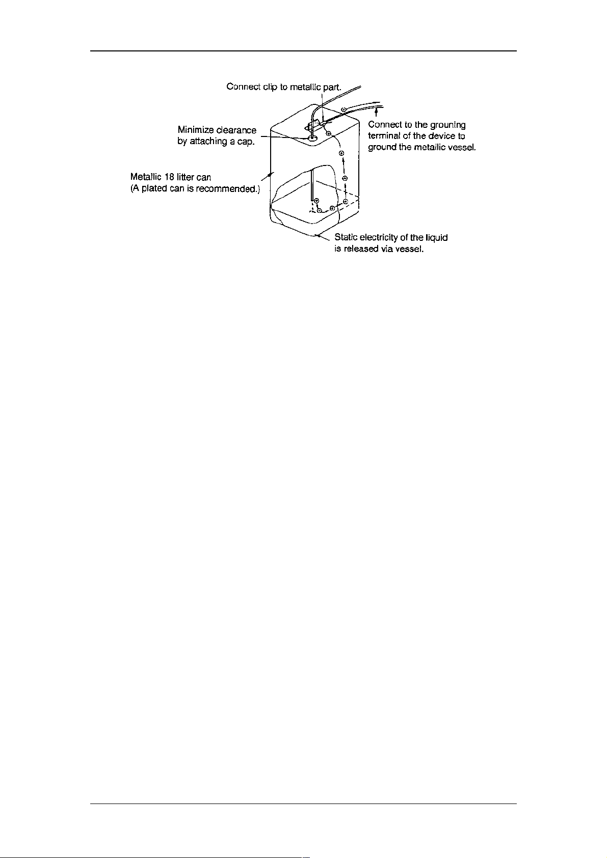
Preventive measure 1.
Use metallic (conductive) waste liquid vessel which is well grounded. This releases
the charge of the waste liquid and vessel to ground.
• Be sure to ground the vessel properly. Disconnecting of grounding wire or poor
grounding defeat the purpose of using a metallic vessel.
• There are some metallic cans which have no conductivity due to an oxidized
coating or lacquer on their surface. Be sure to confirm the grounding of vessels by
a tester before application.
• When a liquid with almost no conductivity (of 10-10s/m or less) is discharged into
the vessel, it is necessary to mix it with another liquid with some conductivity. (The
other liquid can be placed in the vessel in advance.)
Preventive measure 2.
Minimize the clearance of both inlet and outlet of vessel to prevent flame from
entering the vessel.
• Use a cap with three holes for 18 liter and 4 liter cans.
9
Page 12
Operating Instructions RF-2000
Fig.: Anti-static electricity measures for vessel
Preventive measure 3.
Do not approach the vessel with charged objects including the human body.
Charging prevention measures for human body
a) Prevention of charging of shoes and clothes
b) Grounding of human body
c) Make working floor conductive
Suitable products to be used for those measures a), b), and c) are available on the
market.
• When persons who use no charge prevention measures approach dangerous
sections, they have to be grounded beforehand. (For example, they should
contact grounded metal by hand.)
Preventive measure 4.
Use pipes with inner diameter of 2mm or more for waste liquid line for large flow
rates.
• Inclusion of bubbles in the tube may increase the amount of charging by ten times.
Check that there is no inclusion of air via tube joints.
Preventive measure 5.
When it is impossible to use a conductive vessel, use caution in the following points.
a) Set the vessel so that the pipe outlet will be placed below the liquid level in
the vessel. Or, dip a grounded metal (ex. pipe connected to the main body of
device) in the liquid. Please note: This method is not effective for liquid with
small conductivity (10-10s/m or less).
b) Use a vessel of the smallest possible capacity to minimize the damage by fire
if it should occur.
c) Prevent the room from being dry. Humidity of 65% or more has charge
prevention effects.
10
Page 13

Operating Instructions RF-2000
2 General Information
2.1 Outline
The basic design concept of the Dionex Fluorescence Detector RF-2000 is to
enhance productivity of analysis through its highest performance and stability.
This concept is realized by the highest sensitivity of the detector (higher than 300
signal to noise ratio for Raman spectrum of water), the highest wavelength accuracy
(± 2nm), the highest wavelength reproducibility (± 0.2nm) and the GLP/GMP
compliance support and improvement of operational safety.
The Dionex RF-2000 supports operation via the data system CHROMELEON.
Please refer to the sections "7.2 Control from External Equipment via RS-232C" and
"7.2.3 Controlling the RF-2000 via CHROMELEON" for details.
2.2 Features
• Greater sensitivity
The reengineered RF-2000 optical system provides significantly increased
sensitivity (signal-to-noise ratio greater than 300 for Raman spectrum of water).
Furthermore, use of appropriate excitation and emission spectral scan conditions
together with wavelength time programming allow high sensitivity detection of
multiple components at trace level concentrations.
• Enhanced wavelength accuracy
The RF-2000 offers unsurpassed wavelength accuracy (± 2nm) and wavelength
reproducibility to further enhance the reliability of wavelength selectivity and unitto-unit performance.
• Support for GLP/GMP compliance
Daily checks and log-keeping can be automated*. The standard validation
documents such as Certificate of Compliance and Hardware Validation SOP are
provided to facilitate compliance with regulatory requirements.
*With optional System Check software
• Enhanced safety features
Both heat and leak sensors are provided as a standard feature. In addition, the
lamp may be turned ON/OFF via time program, minimizing unnecessary lamp
consumption during continuous, unattended runs.
11
Page 14
Operating Instructions RF-2000
3 Component Location and Function
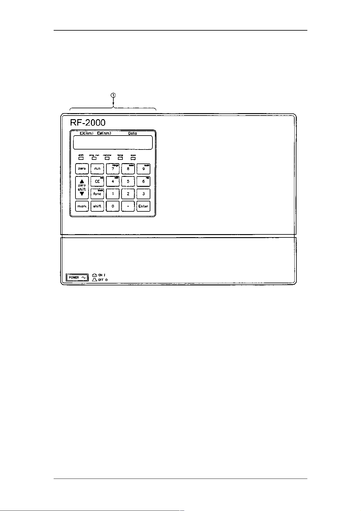
3.1 Front View
No. Description Function
1 Control panel Performs setting and display.
12
Page 15
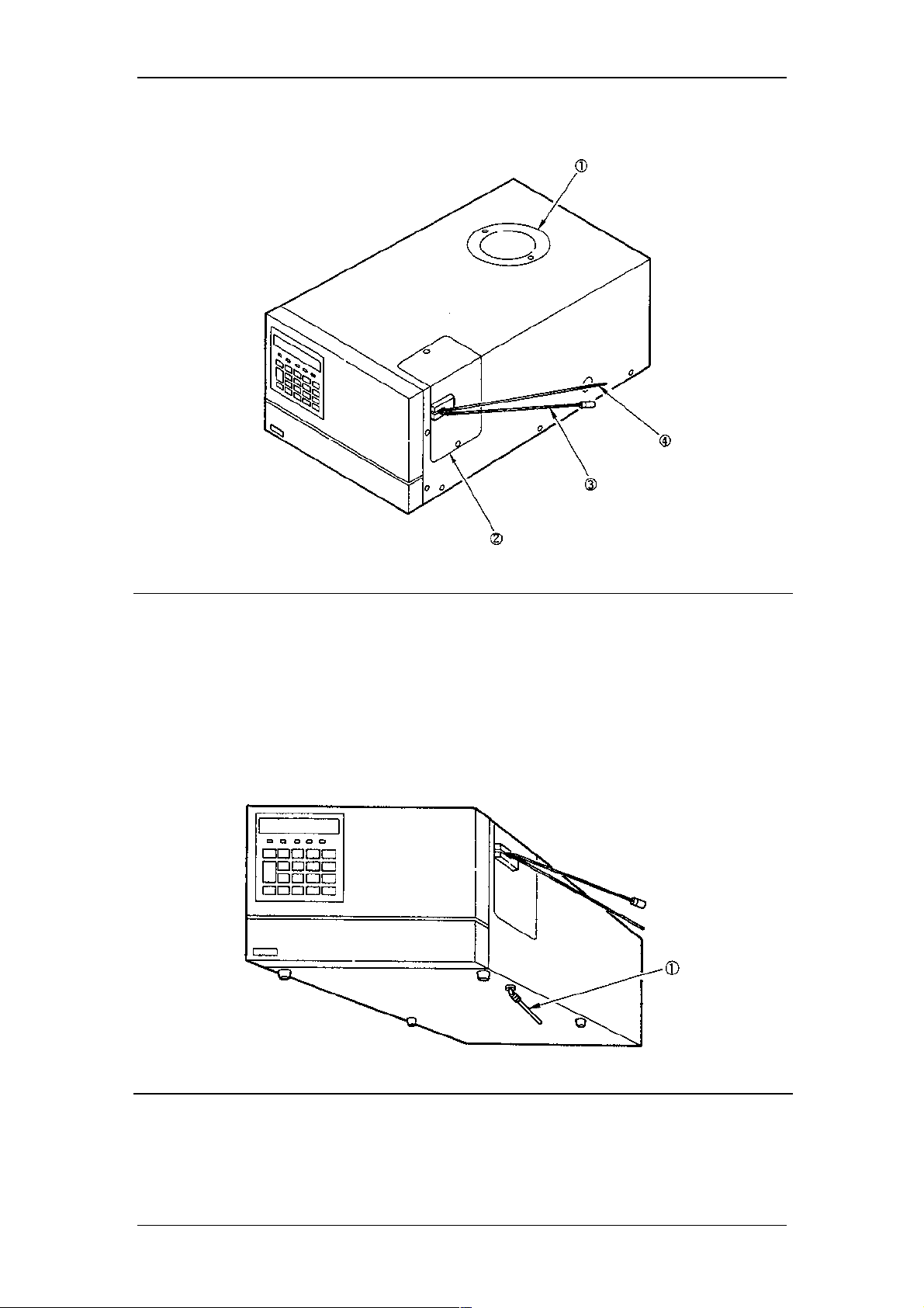
3.2 Top Side and Right Side
Operating Instructions RF-2000
No. Description Function
1 Light source chamber cover Remove this cover when replacing the
lamp.
2 Cell cover Remove this cover when replacing the
cell.
3 Cell inlet tubing Marked with blue cover tubing.
4 Cell outlet tubing
3.3 Bottom Side
No. Description Function
1 Drain tube for solvent leakage Drain tube is connected here.
13
Page 16
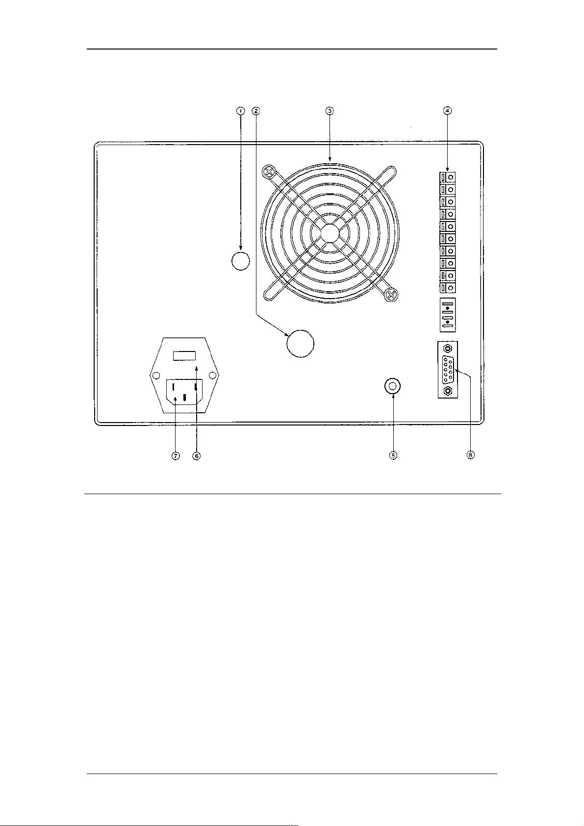
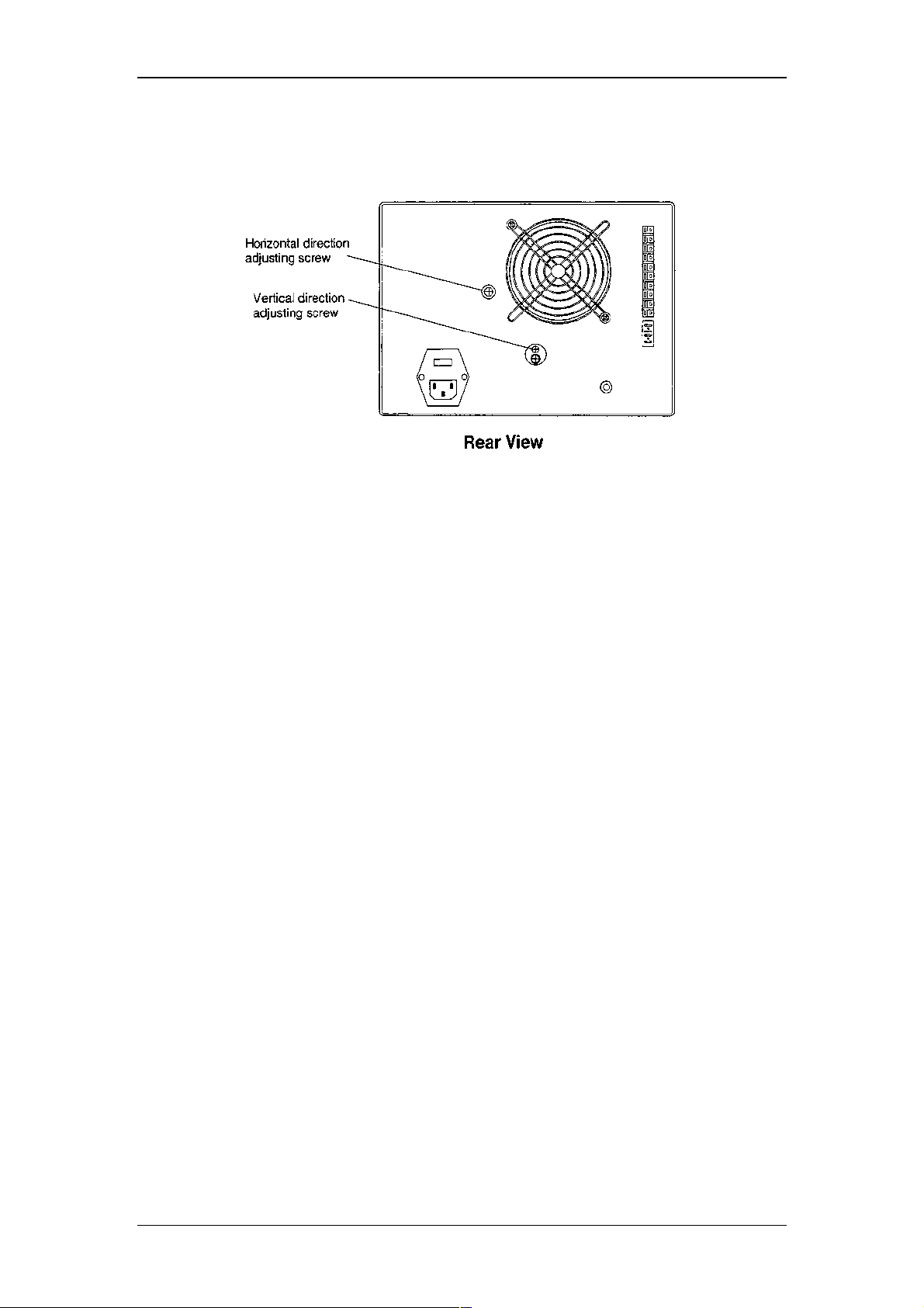
3.4 Rear View
Operating Instructions RF-2000
No. Description Function
1 Horizontal direction adjusting
screw
2/upper Vertical direction adjusting screw Adjusts vertical alignment of the lamp on
2/lower Lamp fixing screw Used to fix the lamp.
3 Fan Removes internal heat.
4 External input and output
terminals
5 Grounding terminal Grounding is made through this terminal.
6 Fuse holder Fuse is set in this holder.
7 Power supply connector Connector for power cable
8 RS-232C connector Connector for control by CHROMELEON
Adjusts horizontal alignment of the lamp
on replacement.
replacement.
Terminals used for connection with
external instruments.
14
Page 17

4 Installation
4.1 Basic Installation Requirements
Operating Instructions RF-2000
Warning:
1. Ventilation Ventilate the room where the high performance liquid
2. Fire Never use fire in the same room where the high
3. Sink Install a sink nearby for flushing eyes or skin which have
4. Corrosive gas and
dust
5. Electromagnetic noise Avoid locations subject to intense magnetic or
6. Space requirements This system is designed to be used on a table or stand,
7. Others Select an installation site with the following parameters to
(1) Maintain room temperature within 4~35C, without
(2) Avoid direct output of a heater or a cooler.
(3) Avoid exposure to direct sunlight.
(4) Avoid locations subject to strong vibrations or
(5) Maintain relative humidity within 45~85%.
(However, humidity should be below 70% when the
To take full advantage of the RF-2000 performance capabilities and
to ensure its operational stability over a long service life, verify that
the selected installation site satisfies the following requirements.
chromatograph is located since the solvent used is
flammable and/or toxic.
performance liquid chromatograph is installed. Also, avoid
installation in the same room of other devices which may
spark. Always keep a fire extinguisher nearby in case of
accident.
been in contact with solvent.
Avoid installation in a place exposed to corrosive gases or
dust.
electromagnetic fields. Use an additional noise filter if
power line noise interferes.
preferably a solid and flat surface with a depth of 70cm or
more.
maintain full performance of the system.
extreme fluctuations.
prolonged weak vibrations.
room temperature is 30C or higher.)
15
Page 18
4.2 Electrical Connections
Operating Instructions RF-2000
Warning:
When the power supply voltage is 220-230V~, operate the unit with
the voltage setting of the power supply connector at the rear of this
unit at 230Vac. When the power supply voltage is at 240V~, set the
power supply connector at 240Vac. For changing the setting of
power supply connector, refer to "8.4 Changing the set power
supply voltage".
If the power supply is not stable or the capacity insufficient,
satisfactory performance is not possible. Verify for the total power
supply for the system before preparing power supply.
• Verify that the power switch of the main unit is turned OFF.
4.2.1 Connection to outlet
(1) Connect the female connector of the power supply cord supplied with the unit
to the power supply cord connector at the rear of the unit, and plug the male
connector into a power supply outlet.
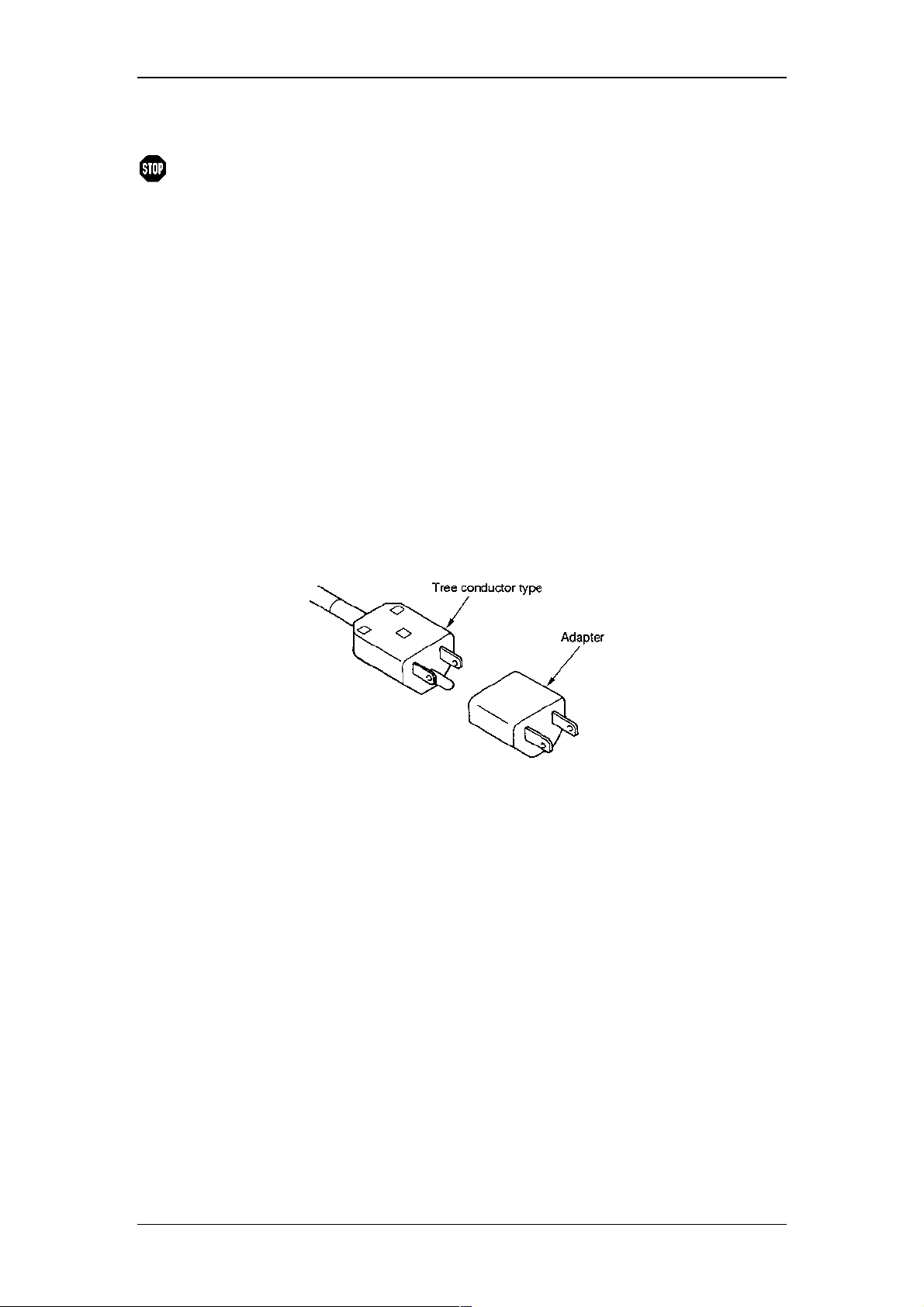
(2) Supplied power supply cord is of three-conductor (3P) type.
When connecting to two-conductor (2P) type power supply outlet, use the
provided power supply adaptor.
4.2.2 Grounding
(1) When three-conductor (3P) type power supply outlet is used, the unit is
grounded by the power supply cord.
(2) When two-conductor (2P) type power supply outlet is used, the unit is not
grounded. In this case, carry out grounding from the grounding terminal on
the unit rear panel.
To prevent electric shock and to secure safe operation of the system, always
ground the unit.
16
Page 19
Operating Instructions RF-2000
4.3 Fluidic Connections
4.3.1 Connecting the Detector and the Column
Typical connection between this equipment and the column is described in this
section.
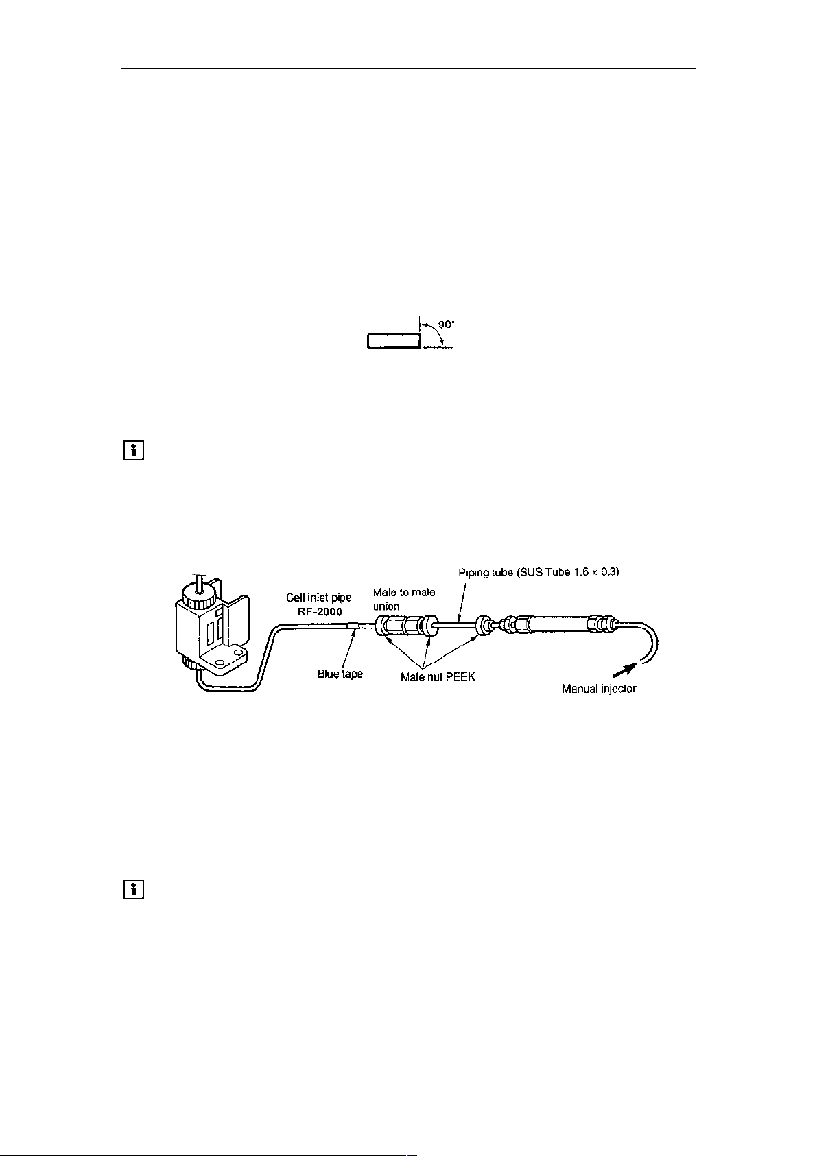
(1) Cut the piping tube (SUS Tube 1.6 x 0.3, standard accessory) at the length
necessary for connecting the column outlet and the cell inlet pipe (pipe with
blue tape) of this equipment.
Cut the tube perpendicular. If the tube is cut diagonally, dead volume is
generated to deteriorate separation.
(2) Connect the piping between the column and the cell inlet pipe with the
supplied male PEEK nut and the male to male union as shown in the figure
below. Tighten the male PEEK nut by the hand firmly. It is not necessary to
use a tool for tightening.
Please note:
Insert the piping tube into the column joint and the male to male
union securely until it comes to the end and then tighten the
male PEEK nut. Similarly, insert the cell inlet pipe until it comes
to the end and tighten the male PEEK nut so that dead volume
is avoided.
4.3.2 Detector Outlet Side Piping
(1) Prepare a waste liquid bottle.
(2) Connect the male to male union and the Tefzel tube (standard accessories of
this product) to the cell outlet pipe and put the other end in the waste liquid
bottle, as shown in the figure.
Please note:
Pressure tolerance of the cell is 1960 kPa {20kgf/cm2} (Value in
{} is for reference). Pressure exceeding this level may cause
leak of liquid or damage of the cell. To prevent such troubles,
pay attention to the following points:
17
Page 20
• Do not apply excessive back pressure to the outlet side of the cell.
• In order to prevent clogging in the flow line, thoroughly clean the flow line before
stop delivery of solvent when the analysis is finished. Especially, when the buffer
solution is used, salts may be crystallized inside flowline. Be sure to clean the flow
line.
• When delivery of the solvent is stopped temporarily, put the tip of the flow line
outlet in the waste liquid in the bottle to prevent clogging of the flow line. This is to
keep inside the flowline being wet.
Operating Instructions RF-2000
Important:
When a mobile phase with high insulation, such as hexane,
is used, it is dangerous since static electricity is changed
at the waste liquid bottle. Use a metal liquid bottle for
waste and ground the bottle.
(Refer to section "1.6 Precautions on Static Electricity")
4.4 Connecting the Recorder and the Integrator
4.4.1 Connecting with a Recorder
Connect the RECORDER terminal of this instrument and the recorder using the
provided signal cable.
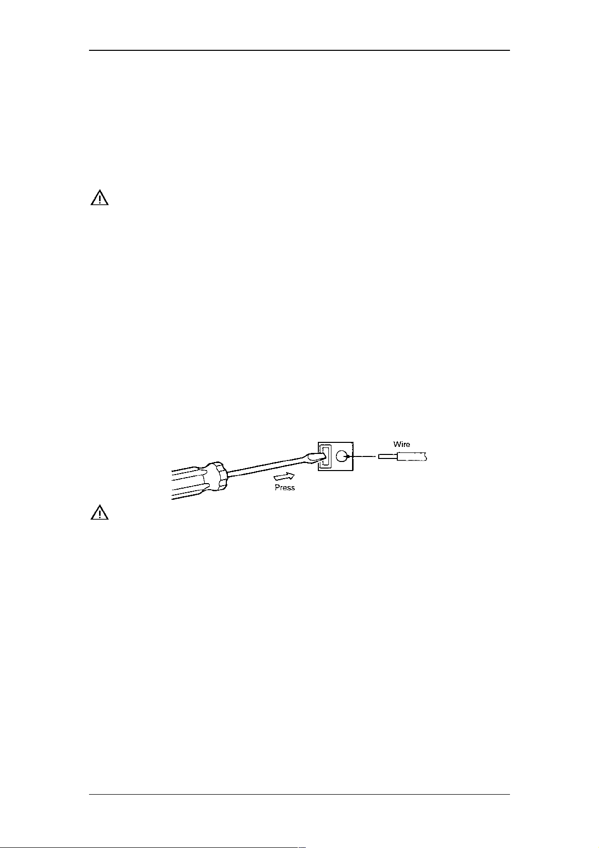
When using a stranded wire, twist the end tightly, or tin it with solder. Using a small
screwdriver or other tool, depress the rectangular button adjacent to the appropriate
terminal hole. Insert the wire and release the button to clamp the wire in position, as
shown in the figure below.
Important:
Be sure to turn the power of the main unit OFF before
connecting the signal cable.
4.4.2 Connecting with an Integrator
Connect the integrator to the INTEGRATOR terminals in the external input/output
terminals at the rear of the RF-2000. Connect the cable supplied with the integrator.
Connect each terminal of the signal cable to the terminal block supplied with the
integrator.
18
Page 21
Operating Instructions RF-2000
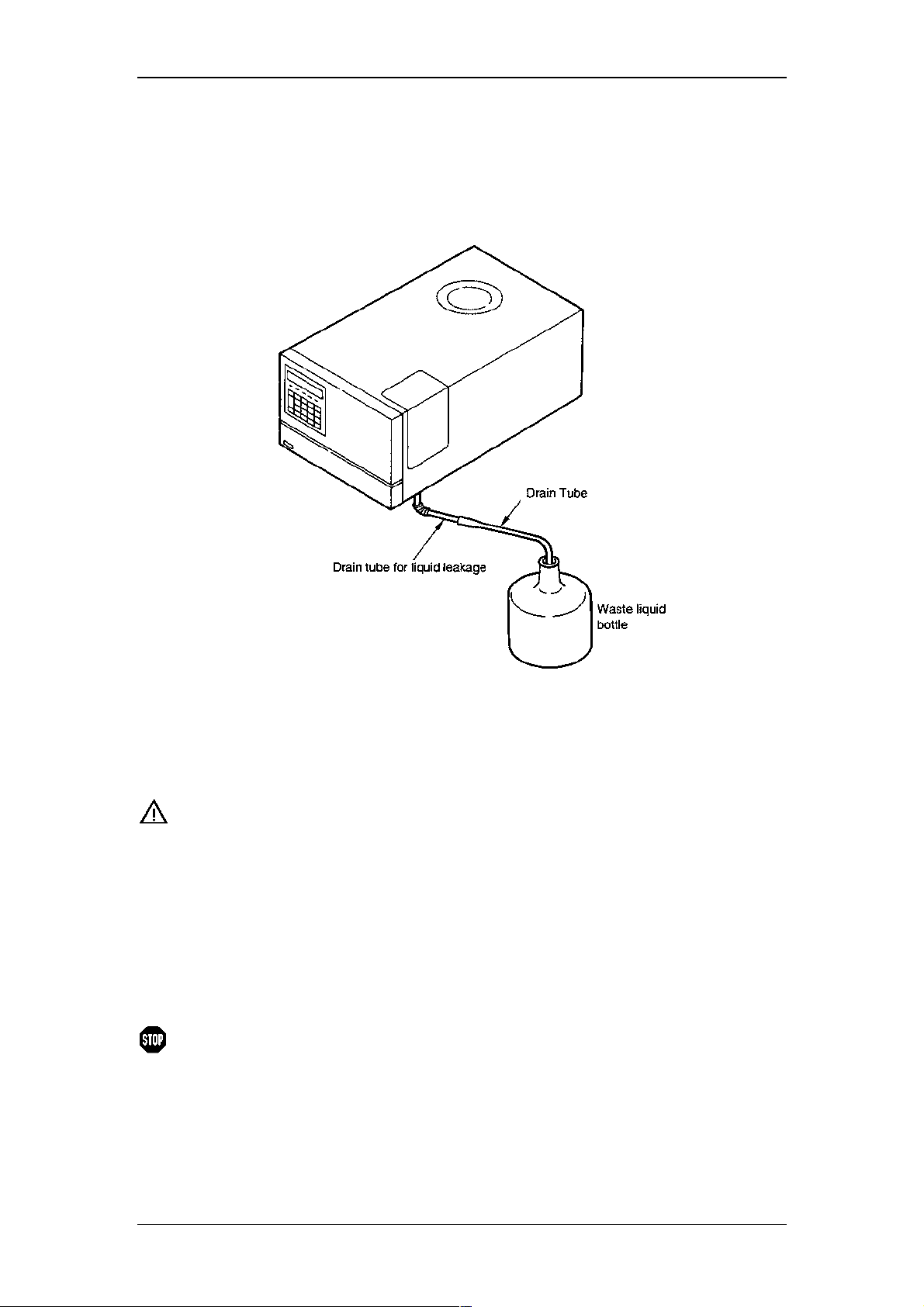
4.5 Connecting a Drain Tube for Solvent Leakage
Each component in the RF-2000 is designed so that liquid leakage in the equipment
is discharged from the liquid leak tube connection port at the right side or the lower
front side of the equipment. Connect liquid leak tube if necessary.
4.5.1 Connecting a Liquid Leak Tube
Cut the drain tube (standard accessory) for liquid leakage at an appropriate length
and connect the waste liquid tube to the drain tube and put the other end in the waste
liquid bottle.
Important:
Place the waste liquid bottle lower than the device at the
bottom. If the flow line of the liquid leak discharging tube is
placed above the bottom face of the RF-2000, the waste liquid
cannot be drained.
4.6 Installing the Xenon Lamp
Be certain that the AC power cable plug is disconnected from this equipment for
prevention of electric shock when installing the xenon lamp.
Warning:
• Be sure to wear protective gears, such as protective mask,
heavy and long sleeve shirt and gloves, when handling the
xenon lamp.
• Since high pressure gas in changed in the xenon lamp, if the
lamp is strongly shocked or the glass surface is scratched,
the lamp may explode and piece of glass may scatter.
19
Page 22
Operating Instructions RF-2000
Warning:
• When the light source chamber cover shall be opened, be
sure to turn OFF the power switch and disconnect the power
cable from power supply.
• It is very dangerous to touch the lamp by any mistake
because high voltage, approx. 30kV, is applied to the + pole
of the xenon lamp when the lamp is lit on and 20V is applied
while the lamp is lit.
• The xenon lamp is still charged just after the power switch is
turned OFF. Leave more than 5 minutes after the power
switch is turned OFF before open the light source chamber
cover to avoid electric shocks.
• It is very high temperature right after the Xenon lamp is
turned OFF. Wait until it is cooled down sufficiently for
replacement. The time required for cooling down the lamp is
an hour when it is left with its power supply turned OFF,
while it is 30 minutes when the lamp is turned OFF with
"LAMP" of the AUX FUNC set at "0".
4.6.1 Installation procedure
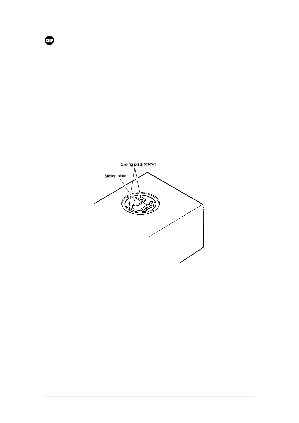
(1) Remove the two mounting screws of the light source chamber cover with a
screwdriver and remove the light source chamber cover.
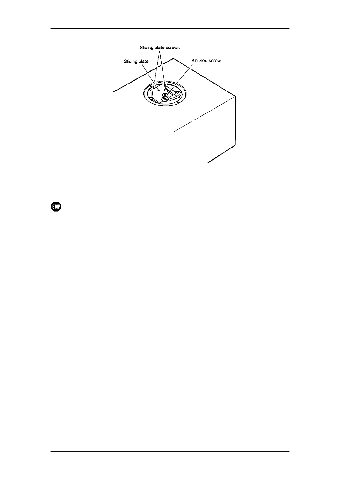
(2) Loosen the sliding plate screws and slide the sliding plate so that the inside of
the light source chamber case can be seen.
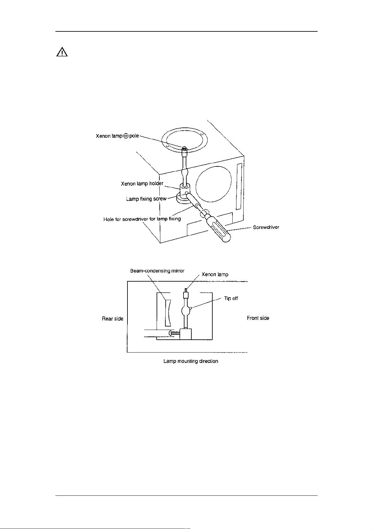
(3) Insert the supplied screwdriver in the hole for screwdriver for lamp fixing along
the guide and turn in counterclockwise to loosen the lamp fixing screw.
(4) Take the xenon lamp out of the case and remove the knurled screws at the
plus pole and the minus pole of the lamp.
(5) Turn the plus pole of Xenon lamp upward, and insert the xenon lamp into the
xenon lamp holder with the gas filling protrusion (tip off) of the xenon lamp
faced to the opposite side of the beam-condensing mirror.
20
Page 23
Important:
When doing this, do not touch the valve surface of the lamp. If
Operating Instructions RF-2000
touched, wipe off the surface with a gauze wet with ethanol
(provided with the lamp), etc. If the lamp is lit with fingerprints
on it, the fingerprints are burned and causes explosion of the
lamp valve.
(6) Tighten the lamp mounting screw with the screwdriver through the hole for
screwdriver for lamp fixing to fix the lamp.
(7) Close the sliding plate and fix it with the sliding plate screws.
21
Page 24
(8) Set the terminal of cable connected to the plus pole in the screw at the plus
pole of the lamp and fix it with a knurled screw securely.
(9) Remount the light source chamber cover.
Operating Instructions RF-2000
Warning:
When tightening the terminal at the plus pole with a
knurled screw, be sure to allow the cable to the plus pole
be bent.
If the plus pole is stretched by the cable, there occurs a
danger that the xenon lamp may be destroyed while being
lit. Besides, when tightening the knurled screw, be sure to
tighten by fingers. It is dangerous to use any tool such as
wrench.
22
Page 25
Operating Instructions RF-2000
4.7 Adjusting the Xenon Lamp Alignment
4.7.1 Adjusting the light source position (coarse adjustment)
Adjust the light source position for maximum equipment performance. Be sure to
adjust the light source position during installation or replacement of the lamp.
Adjustment consists of coarse and fine adjustment.
Please note:
(1) Turning power ON, and make sure lamp LED on the front panel is lit.
(2) Set excitation wavelength to 540nm.
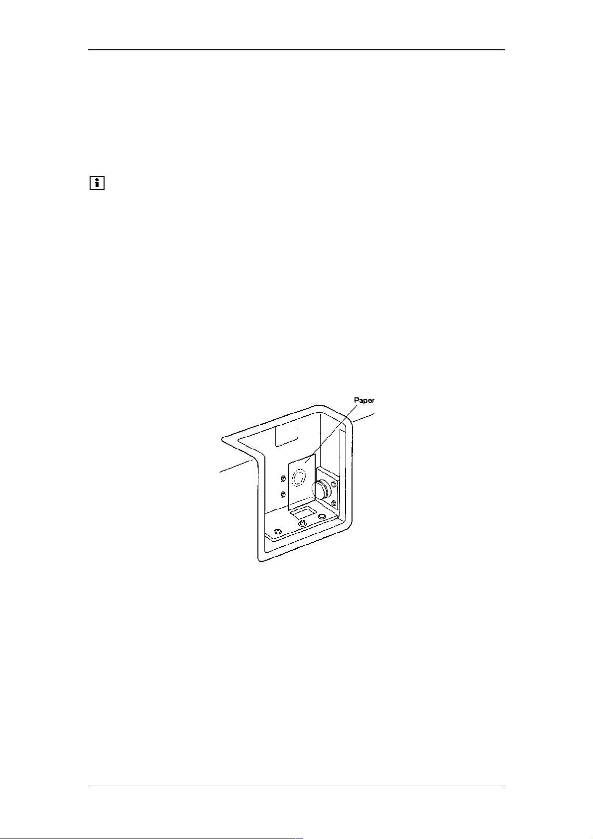
(3) Remove the flow cell and place a piece of white paper where the flow cell was
installed and where green light is observed on the paper.
(4) Adjust the light source horizontal direction adjusting screw for maximum
brightness of the green light on the paper.
(5) Adjust the light source vertical direction adjusting screw in a same way as
above (4).
(6) Remove the paper.
The xenon lamp may not be lit on if the lamp is heated just after
lit off after being lit on for a while. In such case, wait for about
10 minutes until the lamp is cooled and turn ON the power
switch again.
23
Page 26
Operating Instructions RF-2000
4.7.2 Adjusting the light source position (fine adjustment)
Important:
(1) Connect a recorder to the 10mV RECORDER terminal of the RF-2000 (see
section 7.1), and turn the power ON.
(2) Remove the flow cell from the RF-2000. Pour distilled water into the flow cell
using the provided syringe. Make sure that no bubbles are present in the flow
cell, and install the flow cell in the sample compartment (see "8.1
Maintenance of Flow Cell").
(3) Set recorder parameter as follows:
1) Range : 10mV/Full Scale
2) Chart Speed : 10mm/min
(4) Adjust the zero position by pressing the zero key of the RF-2000.
(5) Adjust the zero position of the recorder.
(6) Press func key of the RF-2000 until the fluorescent character displays
(7) Press ENTER.
The parameters are automatically set as follows
(Refer to "5 Operation"):
1) EX : 350nm
2) EM : 450nm
3) GAIN : 2 ( x 4)
4) RANGE : 4 ( x 1/8)
5) RATIO : 0 (OFF)
6) sens : 2 (MED)
7) rsp : 1 (0.1s)
8) Z WAVE : 1 (OFF)
The above parameters are set and the auto-zero function is activated
automatically while the following message appears on the screen.
If a pen recorder is connected, proceed as described below. If
not, please contact the Dionex Service for the fine adjustment of
the light source position.
LAMP ADJUST
Then the emission wavelength is changed and set at 397nm automatically
and the following message appears.
Please note:
SETTING ZERO
LAMP ADJUST XX.XX
Be sure to obey the order of adjustment of the horizontal
direction adjusting screw and the vertical direction adjustment
screw as described below. If the order is not correct, the light
source position deviates greatly from the slit of the excitation
monochromator and re-adjustment cannot be possible. In this
case, carry out the adjustment from "4.7.1 Adjusting the light
source position (Coarse adjustment)" again.
24
Page 27
(8) Adjust the horizontal direction adjusting screw on the rear panel, till the pen
position comes to the maximum point. (till the value in the display indicates its
maximum.)
(9) Adjust the vertical direction adjusting screw on the rear panel till the pen
position comes to the maximum point. (till the value in the display indicates its
maximum.)
(10) Repeat the steps (8) and (9) so that the maximum value at the horizontal
direction adjustment and that of the vertical direction adjustment become the
same. In many cases, the value indicated on display of RF-2000 is more than
30.
(11) Stop recording by the recorder. To stop, press shift down, plot and Enter.
(12) Pressing the CE key resets each parameter at the state before "LAMP
ADJUST" is performed.
Operating Instructions RF-2000
25
Page 28
5 Operation
5.1 Precautions for Operation
Operating Instructions RF-2000
Important:
1. Be sure the sample compartment cover is closed during
measurement. Measurement cannot be made correctly
while the cover is opened.
2. Precautions to prevent clogging of the flow cell. Dusty or
clogged flow cells are the most frequent causes of trouble in
any detector. After analyzing a high-concentration sample,
thoroughly flush it from the flow cell, using a large amount of
mobile phase. Buffer solution crystallizes upon drying, and
can clog the flow cell and tubing. Never leave buffer solution
in the unit as mobile phase. Always flush the flow lines prior
to shutdown of the instrument.
5.2 Fundamentals of Operation
5.2.1 Turning power ON
(1) Push the power switch on the front panel to turn the power ON. Push this
switch again to turn the power OFF.
(2) When the power is turned ON, it operates as follows:
1) Turning power ON
2) All of the dots in the display unit and all the indicator lamps light.
3) Control program version No. is displayed.
4) The instrument seeks the home position of the gratings.
5) When initialization and calibration are done normally, the following
message is displayed and the instrument is ready for operation.
EX(nm) EM(nm) Data
6) Measuring parameters and time program when the power was turned
Please note:
350 400 0.00
off previously are saved.
If an error message is displayed after turning the power ON,
take an appropriate measure as referred in section "9.2 Error
Messages".
26
Page 29
Operating Instructions RF-2000
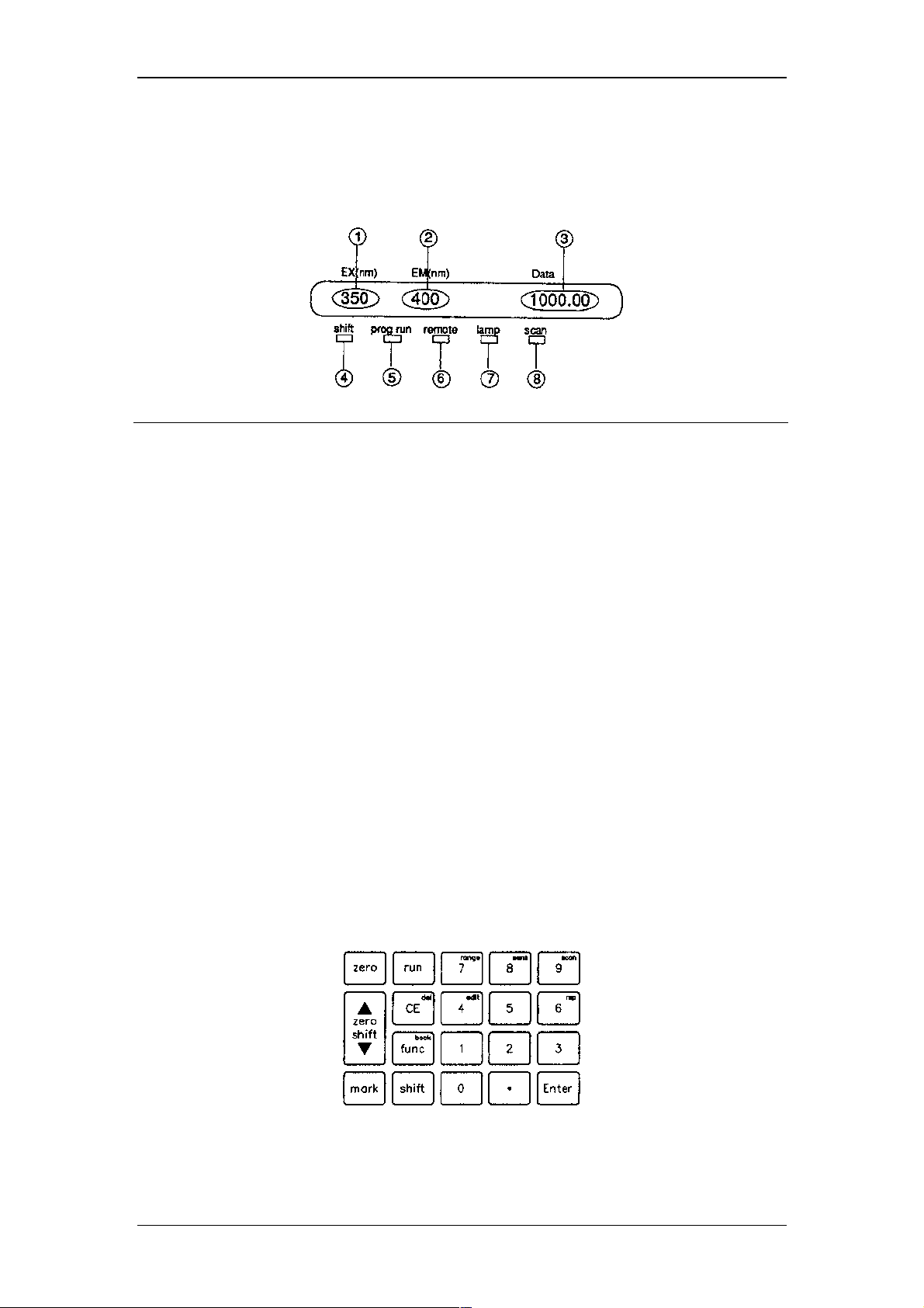
5.2.2 Display unit
The display unit consists of display screen and indicator lamps. Their descriptions
and functions are as follows.
No. Display or description Function
1) EX (nm) Displays excitation wavelength (unit: nm)
2) EM (nm) Displays emission wavelength (unit: nm)
3) Data Displays emission intensity (no unit)
4) shift Shift key indicator lamp
5) prog run Time program operation indicator lamp;
Lights when time program is being executed.
6) remote Remote mode indicator lamp
7) lamp Light source lamp;
Lights when the Xe light source is lighting.
8) scan Scan lamp;
Lights during wavelength scanning.
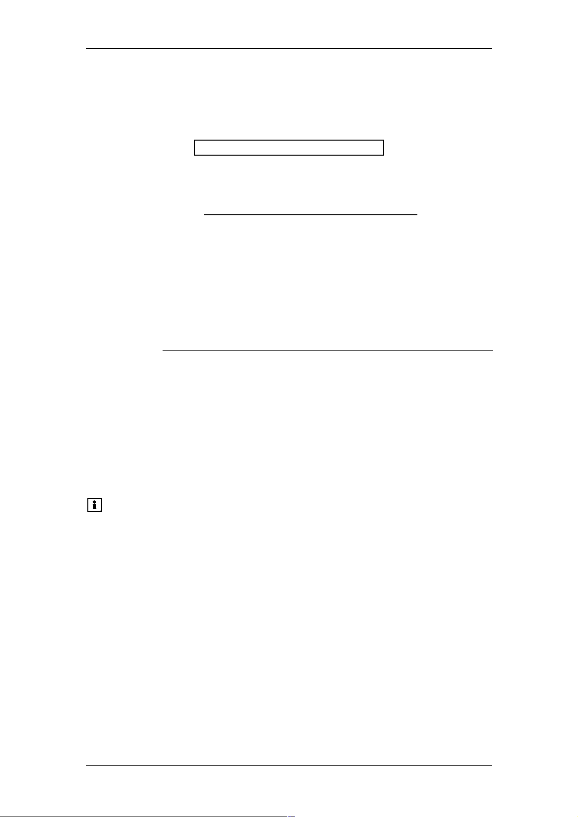
5.2.3 Keyboard
19 keys on the front are used for operation and setting. They are classified into the
following three types:
1) STD-func key
After pressing this key, the specified operation is immediately executed (zero
key, etc.).
2) shift-func keys
Pressing this key after pressing the shift key, the specified operation is
executed (9
3) edit keys
Used for inputting parameters and editing a time program (ten keys, etc.).
scan
key, etc.).
27
Page 30

(1) STD- func keys
Operating Instructions RF-2000
zero
∆∆∆∆ zero shift ∇∇∇∇
mark
run
Auto zero key Pressing this key performs zero adjustment
Zero shift key Zero position on the recorder or integrator
Mark key Mark is added to the data being recorded in
Run key It is a switch to start and stop a time
(2) shift-func keys
shift + edit
shift + range
shift + sens
shift + scan
shift + rsp
Edit key Moves to time program edit mode.
Range key Moves to range setting mode.
Sensitivity key Moves to sensitivity setting mode.
Scan key Wavelength scanning is performed. The
Response key Moves to response setting mode.
of emission intensity.
can be moved by pressing this key. It is
moved upward by pressing the ∆∆∆∆ side and
downward by pressing the ∇∇∇∇ side.
the recorder and integrator by pressing this
key. Mark size: approx. 4mV (INT), approx.
4mV (REC 10mV), approx. 0.4mV (REC
1mV)
program.
scan lamp is lit while scanning.
(3) edit keys
0 - 9
Enter
CE
shift + del
func
shift + back
Numerical keys Numerical values are input with these keys.
Enter key Set input value with this key.
Clear key Returns the display screen to the initial
state.
Input value is cleared by pressing this key
when entering a numerical value. Display
and alarm are cleared by pressing this key
when an error is displayed. But, errors such
as equipment failure cannot be cleared with
this key.
Delete key Deletes a line in the program displayed in
the time program.
Function key Advances to the next setting item in the
display screen.
AUX. FUNC setting screen is forwarded.
Back key Returns to the previous setting item.
AUX. FUNC setting screen is scrolled
backward.
Returns to the previous setting item by
pressing this key while editing a time
program.
28
Page 31

Operating Instructions RF-2000
5.2.4 Setting excitation wavelength and emission wavelength
EX(nm) EM(nm) Data
<<350>> 400
1000.00
The value for excitation wavelength is blinking in the initial state to indicate that the
excitation wavelength can be changed. Pressing the func key, emission wavelength
becomes possible to be changed and pressing shift + back keys in this state,
excitation wavelength becomes possible to be changed again. (Basically, any
blinking value shows being possible to be changed.) Enter a desired wavelength and
press Enter to change the measuring wavelength.
[Example 1]
To change the excitation wavelength from 350nm to 360nm:
(1) Ensure that the value for EX (nm) is blinking.
EX(nm) EM(nm) Data
<<350>> 400
1000.00
(2) Press the keys 3 6 0 and Enter to enter 360nm.
EX(nm) EM(nm) Data
<<360>> 400
1000.00
[Example 2]
To change the emission wavelength from 400nm to 450nm:
(1) Ensure that the value for EM (nm) is blinking by pressing the func key.
EX(nm) EM(nm) Data
360 <<400>>
1000.00
(2) Press the keys 4 5 0 and then Enter to enter 450nm.
EX(nm) EM(nm) Data
360 <<450>>
1000.00
1. When the display is not in the initial state, press the CE key to return to the
initial state.
2. Any value outside the setting range is not accepted. Setting range is 0nm and
from 200nm to 900nm and measuring range is 0nm and from 200nm to
650nm.
29
Page 32
Operating Instructions RF-2000
5.2.5 Setting sensitivity
Setting procedure for sensitivity is as follows:
(1) Press shift + sens. The following is displayed.
EX(nm) EM(nm) Data
SENS <<2>>
Sensitivity can be changed.
(2) Enter the desired set value with numerical key and press Enter.
Set value Sensitivity
1 HIGH
2 MED
3 LOW
Default value at the factory is set at 2 (MED).
Sensitivity MED is 32 times and HIGH is 1024 times as high as LOW sensitivity.
The measurement range can be set as follows by combining with GAIN (refer to the
section "5.5 Additional Functions").
SENS GAIN Sensitivity
magnifications
3 (LOW) 1 (x 1) approx. x 1
3 (LOW) 2 (x 4) approx. x 4
3 (LOW) 3 (x 16) approx. x 16
2 (MED) 1 (x 1) approx. x 32
2 (MED) 2 (x 4) approx. x 128
2 (MED) 3 (x 16) approx. x 512
1 (HIGH) 1 (x 1) approx. x 1024
1 (HIGH) 2 (x 4) approx. x 4096
1 (HIGH) 3 (x 16) approx. x 16384
(3) To return the display to the initial state, press CE.
Please note:
When the values of sensitivity (SENS) and/or Gain (GAIN) are
changed, it is necessary to create a new calibration curve.
30
Page 33

Operating Instructions RF-2000
5.2.6 Setting recorder output range
Procedure to set recorder output range is as follows:
(1) Press shift + range.
The following is displayed.
EX(nm) EM(nm) Data
RANGE <<1>>
Range can be changed.
(2) Enter a desired set value with numerical key and press Enter.
Set value Range
0 Output : 0V
1 x 1
2 x 1/2
3 x 1/4
4 x 1/8
5 x 1/16
6 x 1/32
7 x 1/64
8 x 1/128
9 x 1/256
When the emission intensity is maximum (about 1000) and the range is x1, signal of
about 500mV is output to the 10mVFS terminal and signal of about 50mV is output to
the 1mVFS terminal.
For selecting a range, determine the maximum value of emission intensity to be
recorded in the recorder and apply the value in the following equation to determine
the range.
Range ≤ 20 ÷ (Maximum intensity of emission)
(Common to both 10mVFS and 1mVFS)
[Example] To record the emission intensity in the range of 0 ~ 150 in the
recorder:
Range ≤ 20 ÷ 150 = 1/7.5
In this case, select range x 1/8.
(3) To return the display to the initial state, press CE.
Please note:
When the emission intensity is at the maximum value (1000),
signal of 1V is output to INTEG.1V terminal regardless of setting
of the range.
31
Page 34
Operating Instructions RF-2000
5.2.7 Zero position adjustment for recorder
Adjust the zero position of recorder according to the following procedure before
starting measurement.
(1) Set the measuring range to a required value (refer to the previous item
"Setting recorder output range").
(2) Press zero to set the emission intensity to near 0.
(3) Move the baseline to a desired position using the pen position adjusting knob
of the recorder or pressing the ∆∆∆∆ zero shift ∇∇∇∇ key and start measurement.
The baseline returns to the position set in (3) thereafter by pressing zero.
Please note:
Range variable by pressing the ∆∆∆∆ zero shift ∇∇∇∇ key is as follows:
Approx + 100 ~ approx. - 20 (scale).
5.2.8 Setting response
In this equipment, a digital filter is used to improve S/N ratio.
Responsibility becomes better by setting the filter response fast but noise reduction
effect becomes less.
On the contrary, responsibility becomes worse by setting the response slow, but
noise reduction effect becomes large.
4 steps from 1 to 4 are available as the response for the digital filter by the setting of
parameter "RESPONSE". Responsibilities at each "RESPONSE" value compared to
conventional analog filter and equivalent time constants for analog filter are as shown
in the table below:
RESPONSE value Equivalent time constant
of analog CR filter
1 0.1s 0.2s or more
2 0.5s 1.1s or more
3 1.5s 3.6s or more
4 3.0s 6.6s or more
Setting procedure for RESPONSE:
1) Press shift + rsp. The following is displayed and RESPONSE can be
changed.
EX(nm) EM(nm) Data
Minimum peak width
at half height (Note)
2) Enter the desired value with numerical key and press Enter.
3) Press CE to return to the initial state of display.
Please note:
RESPONSE <<3>>
If response is set slower, responsibility becomes poorer and
peak height becomes lower, and peaks with less width of halfheight show more deterioration of the peak height. Here, the
figures of minimum peak width of half-height indicate for
reference that the peak height becomes 10% lower at each
response setting value. Even when responsibility becomes
poorer and the peak is broadened, the peak area is not
changed.
32
Page 35
Operating Instructions RF-2000
5.3 Operating Procedure in Spectrum Scanning Mode
To seek the optimum excitation wavelength and emission wavelength, this unit is
equipped with a spectrum scan function which can store two sample spectra and one
background spectrum.
This unit can output the spectrum of the excitation light.
• To measure the excitation spectrum or the emission spectrum of the sample, set
the "RATIO" parameter of the "Additional functions" to "1".
• To measure the spectrum of the excitation light, set the "RATIO" parameter to "2"
and the "SPCTYPE" parameter to "1" (refer to "5.5 Additional functions")
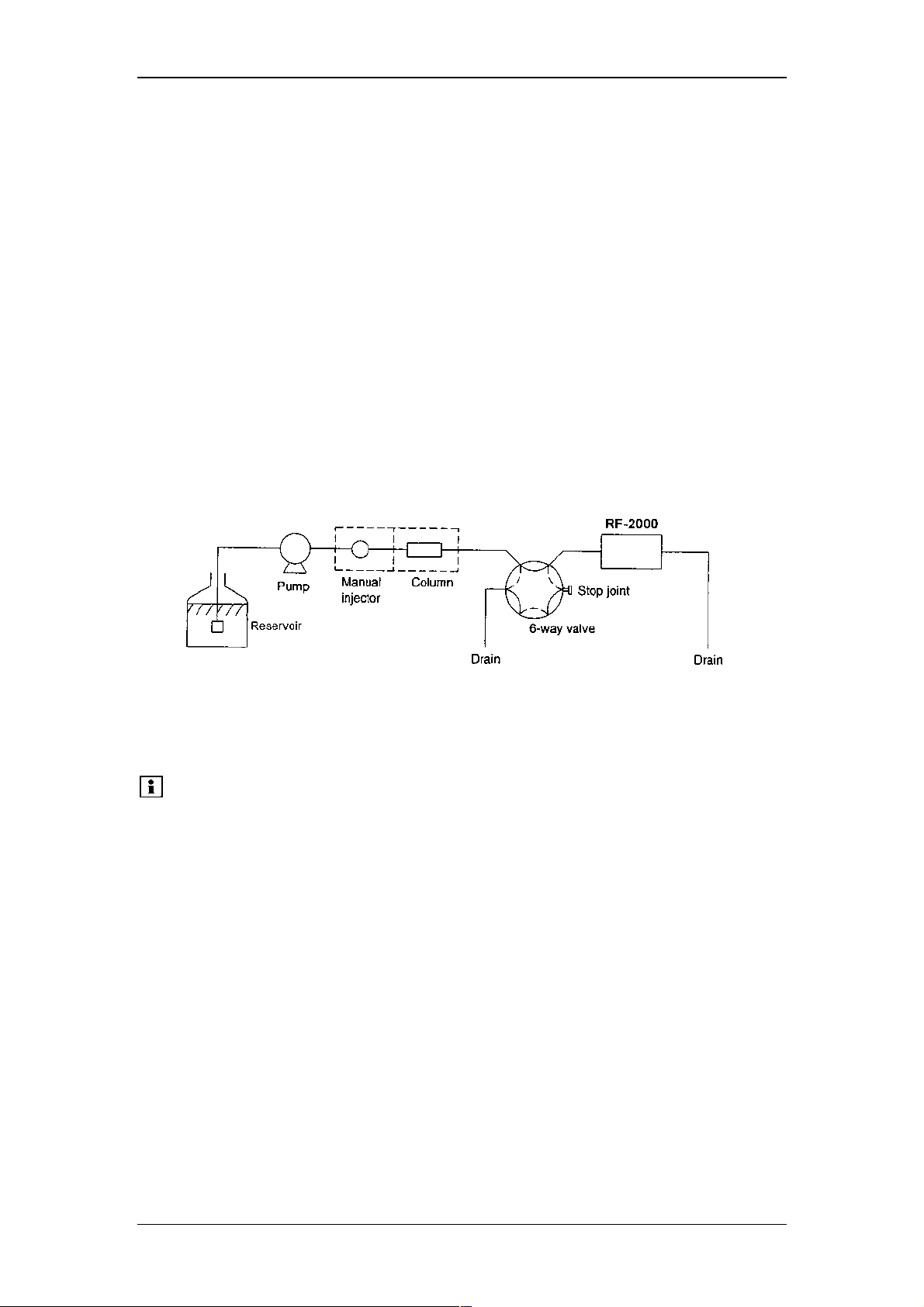
5.3.1 Flow line in spectrum scanning
Liquid in the cell should not be moved while scanning. It is necessary to switch the
flow line by the high-pressure 6-way valve as shown in the figure below:
The 6-way valve is usually set for the flow line indicated by the solid lines and is
switched for the flow line indicated by the broken lines before starting scanning.
As an easier method to stop the flow, the pump may be stopped at the rising of peak.
However, it is necessary to take into consideration that the flow cannot stop
immediately when the pump is stopped.
Please note:
Do not open the drain valve to stop the flow. The life of the
column may be shortened by pressure shock.
33
Page 36
Operating Instructions RF-2000
5.3.2 Setting parameters
Before starting scanning, set the scanning wavelength and scanning speed by AUX.
FUNC.
1) SCAN FILE Scan data file
2) SPC TYPE Scan type (excitation, emission)
3) EX SCAN BGN Excitation scan start wavelength
4) EX SCAN END Excitation scan end wavelength
5) EM SCAN BGN Emission scan start wavelength
6) EM SCAN END Emission scan end wavelength
7) SCAN SPD Scanning speed
SCAN FILE No. 0 is dedicated for background spectrum and FILES No. 1 and 2 are
for samples spectra.
5.3.3 Executing scanning
Press shift + scan to start scanning.
The scan lamp is lit during scanning.
To stop scanning, press shift + scan again.
Please note:
If scanning is executed when previous data is stored in the
SCAN FILE, the previous data is erased and a new data is
stored.
5.3.4 Output of spectrum data
Spectrum data obtained can be output at the recorder or integrator. Before
outputting, select output range, file No. and plot speed. Set the output range. Set the
file No. and plot speed in the parameters SCAN FILE and PLOT SPD in AUX. FUNC.
Set value for PLOT SPD Plot speed
1 1nm/s
2 5nm/s
3 10nm/s
To plot, select and display SPC PLOT in AUX. FUNC and press Enter.
To stop plotting, press Enter again.
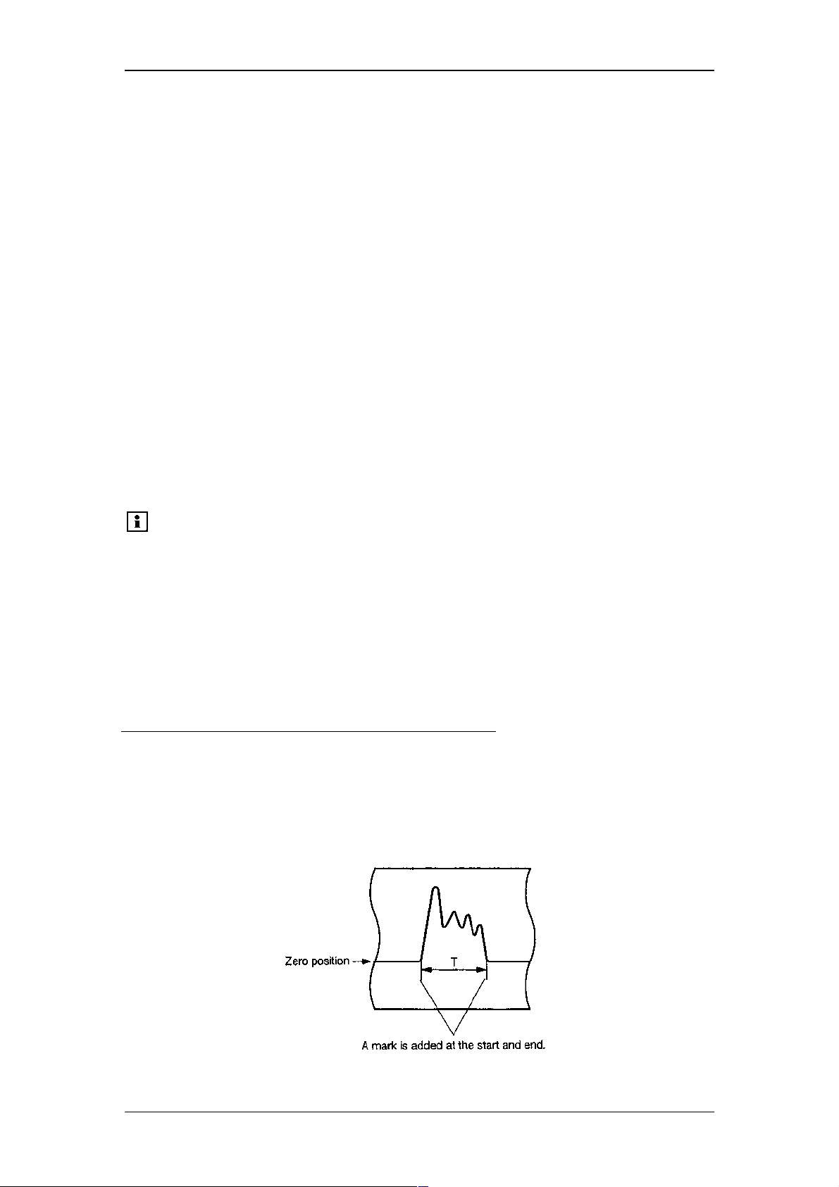
Output example:
34
Page 37
Operating Instructions RF-2000
Please note:
Mark : approx. 4mV (INT)
approx. 4mV (REC 10mV)
approx. 0.4mV (REC 1mV)
Output time T is as follows:
T = (SCAN END - SCAN BGN) /Plot speed (1, 5, or 10nm/s)
For example, when the range from 200nm to 350nm is to be output at the plot speed
of 5nm/s (PLOT SPD = 2):
T = (350 - 200) nm/5nm/s = 30s
Please note:
If the output changes abruptly at the beginning or the end of the
spectrum plot, the mark may not be recorded.
Data in any file which is not scanned cannot be output. If data
does not exist in the specified file, "DATA NOT EXIST"
message is displayed. Similarly, plotting is not possible when
data does not exist in the background file (SCAN FILE = 0).
35
Page 38

Operating Instructions RF-2000
5.4 Creating and Executing a Time Program
5.4.1 Command list
Commands which can be used for a time program are listed below:
Command Description Setting range Remarks
EXλ
EMλ
ZERO Execution of zero
MARK Marking on output for
RANG Output range for recorder 0 ~ 9 Recorder is short-
RESP Response 1 ~ 4
SENS Sensitivity 1 HIGH
GAIN Gain 1 x 1
SCAN Execution of wavelength
EVNT EVENT output of ON/OFF 0 OFF
1 ON
LOOP Repeats time program from
STOP Stops time program. None
LAMP Turn ON and OFF the
Example of time program is shown below:
EX(nm) EM(nm) Data
Excitation wavelength 0, 200 ~ 900
Emission wavelength 0, 200 ~ 900
None
adjustment
None
recorder
2 MED
3 LOW
2 x 4
3 x 16
0 ~ 2 Specifies file no. where
scanning
0 ~ 255
the beginning.
0 means 256
times.
0 OFF
lamp.
1 ON
circuited when it is set
to 0.
scanned data is to be
stored.
0.01 ZERO
Emission intensity is set at 0 in 0.01 minute after starting the time program.
EX(nm) EM(nm) Data
5.00 EX λλλλ 300
In 5minutes, EX (Excitation wavelength) is set at 300nm.
EX(nm) EM(nm) Data
5.00 EM λλλλ 400
In 5 minutes, EM (Emission wavelength) is set at 400nm.
EX(nm) EM(nm) Data
5.10 SENS 3
36
Page 39

In 5.1 minutes, sensitivity is set at 3 (Low).
EX(nm) EM(nm) Data
5.10 GAIN 3
Right after that, gain is set at 3 (x 16).
EX(nm) EM(nm) Data
5.10 RESP 2
Right after that, response is set at 2 (0.5s).
EX(nm) EM(nm) Data
5.10 RANG 5
Right after that, range is set at 5 (x 16).
EX(nm) EM(nm) Data
10.00 MARK
In 10 minutes, marking on the recorder is performed.
EX(nm) EM(nm) Data
Operating Instructions RF-2000
20.00 SCAN 0
In 20 minutes, wavelength scanning is executed and data is stored in file 0. (Type,
wavelength range and speed of the scan should be set in AUX. FUNC in advance.)
EX(nm) EM(nm) Data
999.99 LOOP 2
In 999. 99 minutes, the timer is reset to 0 and the time program is repeated from the
beginning. The time program is executed twice and stopped.
• Since the above time program is just an example for explanation and may not be
adequate for actual measurement.
• The screen display does not change as shown in the above example
synchronously with the time program. Check the program in the edit mode.
5.4.2 Explanation of display screen
It is necessary to enter the edit mode to edit a time program.
(1) Press shift + edit and the following is displayed.
EX(nm) EM(nm) Data
10 USED 22
LEFT
10: Number of steps already set.
22: Number of available steps left.
The above example shows that the time program is set for 10 steps and there are 22
steps available.
37
Page 40

Operating Instructions RF-2000
(2) Press Enter, and the following is displayed.
EX(nm) EM(nm) Data
TIME FUNC
VALUE
Time: Elapsed time from time program start (minute)
Func: Command name
Value: Set value
(3) If a time program is made, the following is displayed by pressing Enter again.
The contents in the display are the same as those in (2).
(Example)
EX(nm) EM(nm) Data
<<1.00>> EX λλλλ 350
The above display indicates that the excitation wavelength becomes 350nm in one
minute from the time program start.
(4) When pressing Enter repeatedly, the time program is displayed in forward
steps.
(5) Pressing shift + back, the time program is displayed in backward steps.
38
Page 41
5.4.3 Flow of setting
Flow in setting a time program is shown below:
EX(nm) EM(nm) Data
<<350>> 400
1000.00
Press shift + edit.
EX(nm) EM(nm) Data
0 USED 32 LEFT
Operating Instructions RF-2000
CE
EX(nm) EM(nm) Data
Press Enter.
<<TIME>> FUNC
VALUE
CE
Enter with numerical keys.
EX(nm) EM(nm) Data
<<10.00>>
CE
EX(nm) EM(nm) Data
Press Enter.
10.00 <<EX λλλλ>>
CE
At each pressing of func, commands are displayed
sequentially. Press Enter while the desired set value is
displayed selected (with numerical keys) and press
Enter.
EX(nm) EM(nm) Data
CE
10.00 RANG
<<VALUE>>
When any command other than ZERO, MARK, and
STOP is selected, enter a desired set value (with
numerical keys) and press Enter.
EX(nm) EM(nm) Data
CE
<<10.00>> RANG 1
Enter a time for the next command.
39
Page 42
Operating Instructions RF-2000
5.4.4 Scanning by program
Example setting to execute scanning in 5 minutes and store data in file No. 2 using a
program is shown below:
(1) Press CE to return to the initial screen.
EX(nm) EM(nm) Data
<<350>> 400
1000.00
(2) Press shift + edit.
EX(nm) EM(nm) Data
0 USED 32
LEFT
(3) Press Enter.
EX(nm) EM(nm) Data
<<TIME>> FUNC
VALUE
(4) Enter a time (minute). Press 5 and Enter.
EX(nm) EM(nm) Data
5.00 <<EX λλλλ>>
(5) Select a command. Press func repeatedly until SCAN is displayed.
Press Enter to set SCAN.
EX(nm) EM(nm) Data
5.00 SCAN
<<VALUE>>
(6) Enter a file No. where data is to be stored. Press 2 and Enter.
EX(nm) EM(nm) Data
<<5.00>> SCAN 2
(7) Enter the second and later steps if necessary by repeating (4) to (6). To finish
setting the program, press CE twice.
Please note:
• When setting multiple steps, it is not necessary to set the
commands in order of time. They are automatically
rearranged.
• Set the STOP command at the end of a program unless the
program is to be executed repeatedly.
• In selecting a function, the previous function is displayed by
pressing shift + back.
40
Page 43

Operating Instructions RF-2000
5.4.5 Deleting a step
Display the step desired to be deleted and press shift + del.
(1) Display the step desired to be deleted.
EX(nm) EM(nm) Data
<<5.00>> EX λλλλ 300
(2) Press shift + del.
EX(nm) EM(nm) Data
<<20.00>> EM λλλλ 420
The step displayed in the program is deleted and the next step is displayed if any.
When any next step is not set, the following is displayed.
EX(nm) EM(nm) Data
0 USED 32 LEFT
5.4.6 Start and stop
After setting a time program, start and stop the time program according to the
following procedure:
(1) To start a time program:
Press run.
The LED for prog run is lit.
(2) To stop the time program:
When the program is stopped, it returns to the state just before the time
program is started.
There are two ways to stop a time program: forced stop of the program being
executed, and stop of a time program by STOP command in the program.
Procedure of forced stop of the time program is as follows:
Press run.
The LED for prog run is lit. Now the time program stops.
5.4.7 LOOP command
A program can be repeated for the number of times set by LOOP command.
The LOOP is a command to reset TIME at 0.00 and start the program again.
TIME FUNC VALUE
1) 15.00 EXλ 300
2) 20.00 EXλ 350
30.00 LOOP 3
In the above setting, steps 1) and 2) are repeated 3 times in a cycle of 30 minutes.
Please note:
• Steps set after the LOOP command are invalid.
• Up to 255 can be set as the VALUE for LOOP command.
When 0 is set for the value, the program is repeated 256
times.
41
Page 44

Operating Instructions RF-2000
5.5 Additional Functions
AUX. FUNC (AUXILIARY FUNCTION) is equipped in this instrument.
5.5.1 AUX. FUNC List
Type Command Function
4 TIME Displays the elapsed time while a time program is
executed (when MONIT-TIME is set)
4 SMPL EN Displays output from emission measurement sensor
4 REF EN Displays excitation light beam monitor value
1 GAIN Sets gain. (1 = x1, 2 = x4, 3 = x16)
1 SCAN FILE Sets file No. Where scan data is to be stored
(0=Background, 1 and 2=Sample)
1 SPC TYPE Sets scan type. (1=EX, 2=EM)
1 EX SCAN BGN Sets excitation scan start wavelength. (200 ~ 900nm)
1 EX SCAN END Sets excitation scan end wavelength. (200 ~ 900nm)
1 EM SCAN BGN Sets emission scan start wavelength. (200 ~ 900nm)
1 EM SCAN END Sets emission scan end wavelength. (200 ~ 900nm)
1 SCAN SPD Sets scanning speed. (1=SUPER, 2=FAST,
3=MED,4=SLOW)
1 PLOT SPD Sets output speed of spectrum data to recorder.
(1=1nm/sec, 2=5nm/sec, 3=10nm/sec)
3 SPC PLOT Outputs spectrum data to recorder.
1 EVENT Sets EVENT OUT terminal status. (0=OFF, 1=ON)
1 EXT-S Used when EVENT OUT terminal is used for starting
external equipment, etc.
(0=EVENT, 1=Time program, 2=Unreleasable error,
3=Wavelength scan)
1 MONIT-TIME Sets when elapsed time is desired to be displayed in
executing a time program. (0=not to display, 1=to display)
1 LAMP Sets ON/OFF of Xe lamp. (0=OFF, 1=ON)
1 RATIO Decides operation of light source compensation by
division.
(0= without division, 1 = with division, 2 = Excitation light
energy)
4 XE TIME Displays accumulated operating time of xenon lamp.
1 Z WAVE Sets the output holding function when setting of
wavelength, sensitivity and gain is changed. (0=set, 1=not
set)
3 RS232C Sets communication parameters of RS-232C and activates
remote control mode. Refer to "7.2 Control from external
system via RS-232C".
3 CLOSE KEY Refuses any key input.
3 LAMP ADJUST Enters lamp position adjusting mode.
3 S/N CHECK Used for Performance Check.
"Type" in the above table indicates a kind of operating procedure.
Type 1: Enter a desired value with numerical keys and press the Enter key.
Type 3: Press the Enter key to execute the function.
Type 4: The status is displayed without any key operation.
42
Page 45

Operating Instructions RF-2000
5.5.2 Setting procedure for AUX. FUNC
TIME
(Display of elapsed time of time program)
EX(nm) EM(nm) Data
TIME
100.00
This function displays the elapsed time from the program start while the time program
is executed.
However, this is displayed only when MONIT-TIME is set to 1 in AUX. FUNC.
SMPL EN
(Output from emission measurement sensor)
EX(nm) EM(nm) Data
SMPL EN XXX.X
This function displays output from emission measurement sensor (Photo multiplier
tube).
REF EN
(Excitation light beam monitor value)
EX(nm) EM(nm) Data
REF EN XXX.X
This function displays output from excitation light beam monitor (Photodiode).
GAIN
(Setting of gain)
EX(nm) EM(nm) Data
GAIN __
This function sets gain for signal from the detector. Enter a desired value with
numeric key and press Enter.
Default set value at the factory is "2" (Gain = x 4). For general use, "2" (Gain = x 4)
can be applied.
Set value Gain
1 x1
2 x4
3 x16
43
Page 46
Operating Instructions RF-2000
Magnification can be set as follows by combining with SENS (refer to section "5.2.5
Setting Sensitivity").
SENS Sensitivity
magnifications
3 (LOW) approx. x 1
3 (LOW) approx. x 4
3 (LOW) approx. x 16
2 (MED) approx. x 32
2 (MED) approx. x 128
2 (MED) approx. x 512
1 (HIGH) approx. x 1024
1 (HIGH) approx. x 4096
1 (HIGH) approx. x 16384
Please note:
When values of sensitivity (SENS) and/or Gain (GAIN) are changed,
it is necessary to create a new calibration curve.
SCAN FILE
(Setting of scan file)
EX(nm) EM(nm) Data
SCAN FILE __
This function sets No. of file where scan data is to be stored. Enter the desired file
No. with numerical key and press Enter.
Set value Type
0 Background
1, 2 Sample
SPC TYPE
(Setting of scan type)
EX(nm) EM(nm) Data
SPC TYPE __
This function sets spectrum scan type. Input a set value with numeric key and press
Enter.
Set value Type
1 Excitation scanning
2 Emission scanning
EX SCAN BGN
(Setting of excitation scan start wavelength)
EX(nm) EM(nm) Data
EX SCAN BGN _ _ _
This function sets start wavelength for excitation scanning.
Enter the desired start wavelength with a numeric key and press Enter (200 ~ 900).
44
Page 47
Operating Instructions RF-2000
EX SCAN END
(Setting of excitation scan end wavelength)
EX(nm) EM(nm) Data
EX SCAN END _ _ _
This function sets end wavelength for excitation scanning.
Enter the desired end wavelength with a numeric key and press Enter (200 ~ 900).
Please note:
EX SCAN BGN should be smaller than EX SCAN END.
EM SCAN BGN
(Setting of emission scan start wavelength)
EX(nm) EM(nm) Data
EM SCAN BGN _ _ _
This function sets start wavelength for emission scanning.
Enter desired start wavelength with numeric key and press Enter (200 ~ 900).
EM SCAN END
(Setting of emission scan end wavelength)
This function sets end wavelength for emission scanning.
EX(nm) EM(nm) Data
EM SCAN END _ _ _
Enter desired end wavelength with numeric key and press Enter (200 ~ 900).
Please note:
EM SCAN BGN should be smaller than EM SCAN END.
SCAN SPD
(Setting of scanning speed)
EX(nm) EM(nm) Data
SCAN SPD __
This function sets scanning speed.
Enter the desired set value with numeric key and press Enter.
Set value Scanning speed
1 SUPER (approx. 3000nm/min)
2 FAST (approx. 600nm/min)
3 MEDIUM (approx. 120nm/min)
4 SLOW (approx. 24nm/min)
Please note:
When scanning speed is set to super, spectrum data is stored
at an interval of 4nm. When scanning speed is set to the other
value, spectrum data is stored at an interval of 1nm.
PLOT SPD
(Setting of plot speed)
EX(nm) EM(nm) Data
PLOT SPD __
45
Page 48

Operating Instructions RF-2000
This function sets output speed of spectrum data to the recorder or integrator. Enter
the desired set value with numeric key and press Enter.
Set value Output speed
1 1 nm/s
2 5 nm/s
3 10 nm/s
Please note:
When recording to a recorder or an integrator is performed
simultaneously with wavelength scanning, data is kept being
output to the recorder or integrator regardless of this setting.
SPC PLOT
(Output of spectrum)
EX(nm) EM(nm) Data
SPC PLOT
This function outputs spectrum data in the file set in SCAN FILE to a recorder or an
integrator.
Press Enter to start outputting to the recorder.
EVENT
(Setting of EVENT OUT terminal)
EX(nm) EM(nm) Data
EVENT __
This function sets ON (close) / OFF (open) of EVENT OUT terminal (relay contact)
located in the rear side of this equipment.
Enter the desired set value with numeric key and press Enter.
Set value EVENT OUT terminal
0 OFF (open)
1 ON (close)
EXT-S
(Function setting of EVENT OUT terminal)
EX(nm) EM(nm) Data
EXT-S __
This function specifies control mode for external instruments by EVENT OUT
terminal.
Enter the desired set value with numeric key and press Enter.
Set value Output speed
0 EVENT output is controlled by EVENT set
value.
1 Relay is turned ON for about one second
at a time program start.
2 Relay is turned ON at an occurrence of
error which cannot be reset.
3 Relay is turned ON during wavelength
scanning.
46
Page 49
Operating Instructions RF-2000
MONIT-TIME
(Setting of display of elapsed time of time program)
EX(nm) EM(nm) Data
MONIT-TIME __
This function displays the elapsed time from the time program start.
It is displayed on the TIME screen in AUX. FUNC.
Enter the desired set value with numeric key and press Enter.
Set value Function
0 Cancels display of elapsed time
1 Sets display of elapsed time
LAMP
(Setting of xenon lamp ON/OFF)
EX(nm) EM(nm) Data
LAMP __
This function controls ON/OFF of xenon lamp.
Set value Xenon lamp
0 OFF
1 ON
Please note:
When the xenon lamp is lit on, this instrument performs
initialization. After completion of initialization, all set values are
reset to the state before lit on lamp.
RATIO
(Setting of division correction to output signal)
EX(nm) EM(nm) Data
RATIO __
This instrument corrects the change of the fluorescence light energy caused by the
change of excitation light energy by dividing the monitored excitation light energy.
This function sets this correction.
Generally, this division correction is performed (Set value: 1).
Set value Functions
0 Outputs the fluorescence light energy.
1 Executes the division correction.
(Outputs the ratio of "fluorescence/
excitation")
2 Outputs the excitation light energy.
Please note:
When the xenon lamp is OFF (see item of LAMP), the value is
automatically set to "0" (outputs fluorescence light energy).
When the value is set to "1" (executes division correction) or "2"
(output the excitation light energy.) before the lamp is turned
OFF, the value is again set to "1" or "2" after the lamp is turned
ON.
47
Page 50
Operating Instructions RF-2000
During scanning the excitation wavelength, this unit measures the spectrum without
the division correction, because the corrected spectrum may not indicate the
optimum excitation wavelength for analysis with this unit.
XE TIME
(Display of operating time of xenon lamp)
EX(nm) EM(nm) Data
XE TIME 100
This function displays accumulated operating time of xenon lamp (Unit: hour).
Press 0 and Enter to reset the accumulated time to 0.
Please note:
Do not reset the time except for when replacing the lamp.
Z WAVE
(Output holding function at change of wavelength, sensitivity or gain)
EX(nm) EM(nm) Data
Z WAVE __
This function sets operation/non-operation of output holding function on changing
wavelength, sensitivity or gain.
Set value Correction
0 Operation
1 Non-operation
Please note:
If the wavelength is changed, light energy in the background
changes and the output value varies. By setting this operation
(set value: 0), the output value does not vary when the
wavelength is changed. When changing the wavelength during
the analysis, set this operation.
This function can not operate correctly when response value is
set at "4-(3.0sec)".
RS232C
(Setting of RS-232C and starting communication)
EX(nm) EM(nm) Data
RS232C
Press the Enter key to display the commands for starting the communication and
setting parameters of RS-232C (see "7.2 Control from External equipment via RS232C").
CLOSE KEY
(Rejects any key input.)
EX(nm) EM(nm) Data
CLOSE KEY
This function refuses any key input.
After pressing Enter, any key input is rejected.
48
Page 51

Operating Instructions RF-2000
To cancel this function, press shift and CE simultaneously.
LAMP ADJUST
(Lamp position adjustment)
EX(nm) EM(nm) Data
LAMP ADJUST
Press Enter to enter the xenon lamp position adjusting mode and the light source
intensity is displayed. For adjusting procedure, see section "4.7.1 Adjusting the light
source position."
S/N CHECK
(Performance check)
EX(nm) EM(nm) Data
S/N CHECK
Press Enter to go to the performance check mode.
In this mode, you can perform a sensitivity check, noise width measurement and
calculation of S/N value. The following message is retained on the screen, since the
parameter settings of the integrator must be changed for these measurements.
EX(nm) EM(nm) Data
S/N CHECK
ENTER
To continue the measurement, press Enter. To exit from this mode and return to the
initial screen, press CE.
49
Page 52

Operating Instructions RF-2000
6 Performance Verification
Inspection Environment
Carrying out inspection measurements in an environment where the equipment is
exposed to sudden changes of temperature or to air currents may affect the
repeatability of the data.
Inspections should be conducted in locations where changes of room temperature
are less than 2°C. Places where the equipment is exposed to strong air currents from
air conditioners should particularly be avoided.
Appropriate Location For proper and safe use of the equipment, select a site
in consideration of the following.
1. Corrosive Gas and Dust To extend the life of your equipment and maintain the
proper performance standards, avoid using your
equipment at a site exposed to corrosive gas or dust.
2. Ventilation and Fire If flammable liquids or toxic solvents are used, be sure
to ventilate the room well. Never use fire in the room
when flammable solvents are used.
3. Electromagnetic Noise Never use your equipment near devices that generate
strong magnetism. If the electrical power line generates
electrical noise, connect your equipment to a power line
with a commercially available filter.
4. Workspace Your equipment is designed to be used on a desk or
similar surface. Use only a firmly fixed, flat surface that
is at least 70 cm deep. If another piece of equipment is
to be placed to the left of the unit, be sure to provide at
least 15mm of space between the units.
In order to maintain the performance of your equipment, avoid subjecting it to:
(1) Direct air currents from air conditioners
(2) Direct sunlight
(3) Vibration
(4) High temperature or humidity. The room temperature should be within the
range of 4°C to 35°C, and the humidity between 45% and 85%, with minimum
fluctuation in room temperature. (However, humidity should be below 70%
when the room temperature is 30°C or higher.)
50
Page 53

Operating Instructions RF-2000
6.1 Outline of System Validation
6.1.1 Outline
For the holistic validation of HPLC system, chromatographic analysis is performed
under the analytical conditions specified by the manufacturer. The system status can
be judged based on the obtained results. This is because the failure of the LC system
may depend on the analytical conditions. Holistic validation procedure described in
this manual is the standard for checking the status of the LC system, serving as the
basis of inspection.
In routine operation, the operators must perform a system suitability test under the
pre-determined analytical conditions. If any problem occurs under such conditions,
perform holistic validation first described in this manual. If the result of holistic
validation meets the acceptance criteria, the LC system itself is working properly and
the cause of the problem is related to the analytical method itself. On the other hand,
if the results do not meet the acceptance criteria for holistic validation, it implies that
there is a problem in the LC system itself and modular validation should be
performed for diagnosis of each LC module.
The repeatability (relative standard deviation) of retention time, peak area, and peak
height is measured to check whether the values meet the acceptance criteria.
6.2 Repeatability Test of Chromatographic Data (Isocratic LC)
6.2.1 Purpose
The purpose of this test is to confirm that the chromatographic data can be obtained
with good repeatability for the LC system to be inspected. An HPLC System for this
inspection consists of the pump, detector, column oven, autosampler and data
system.
6.2.2 Preparation for Inspection
(1) Prepare the following parts and reagents:
(a) Isocratic LC system
(b) Mobile phase (acetonitrile/water = 4/1 (v/v)
* Use acetonitrile and water of HPLC grade.
(c) Column
(4.6mm ID X 150mm)
(d) Sample
* Mixture of two components (acridine and anthracene)
[Method for sample preparation]
Place 10mg of acridine and 10mg of anthracene in the volumetric flask of
100ml capacity. Add 100ml acetonitrile and shake it to dissolve. Transfer 1ml
portion of the sample solution into the 10ml volumetric flask and add
acetonitrile, resulting in a total volume of 10ml.
(e) Water (HPLC grade or equivalent)
(f) Isopropyl alcohol
51
Page 54

(2) Check the connection of the units. Refer to the instruction manuals for details
of the connection of each unit.
(3) Before installing the column, observe tubing connection of the LC system.
Use tubing with 0.3mm I.D. or less from the outlet of auto injector to the
column inlet and from the column outlet to the detector inlet. Length of the
tubing should be 30cm or less to minimize the extra-column band broadening.
(4) Flush the flow line with appropriate solvents dependent on the operation
status of the system. General guideline is shown below. To flush the flow line
with solvents, connect the inlet and outlet tubing of the column directly using a
proper union.
Column should be connected after flushing.
* Newly installed system
Flush the flow line with isopropyl alcohol, then with water at a flow rate of 2
ml/min for ten minutes.
* When low polarity solvent (such as hexane) is used as the mobile
phase in the system:
Flush the flow line with isopropyl alcohol, then with water at a flow rate of 2
ml/min for ten minutes.
* When mixture of water and organic solvent, or organic solvent
miscible with water (methanol, acetonitrile, etc.), or buffer solution is
used as the mobile phase in the system:
Flush the flow line with water at a flow rate of 2 ml/min for ten minutes.
(5) Set the mobile phase (b) and flush the flow line, then connect the column (c)
to the LC system.
Operating Instructions RF-2000
6.2.3 Procedure
The outline of the procedure is described below:
(1) Set the flow rate of the pump to 1ml/min and column oven temperature to
40°C. Start pump flow and temperature control. Then, confirm that the solvent
comes out from the outlet tubing of the detector and no leak of solvent is
observed at the connection.
(2) Set the parameters of detector.
EX (nm) : 360 GAIN : 1
EM (nm) : 450 LAMP : 1
Response : 2 RATIO : 1
Sens : 2
(3) Monitor the baseline. When a stable baseline is obtained, press the zero point
adjustment key of the detector. Then, inject 10µl of mobile phase and confirm
no peak is observed.
(4) Next, inject 10µl of test sample solution. Repeat measurement at least five
times.
(5) Obtain the chromatographic data of retention time, peak area, and peak
height from five successive analyses.
(6) Calculate the average (X) of the data and %RSD using the equations as
shown below.
52
Page 55

Operating Instructions RF-2000
SD
5
å
=
i
1
=
2
)(
−
XAXI
4
XA = (X1 + X2 + ...... + X4 + X5) / 5
%RSD = (SD / XA) * 100
X1 .....X5 : Data
XA : Average
SD : Standard deviation
%RSD : Relative standard deviation
Acceptance Criteria
The acceptance criteria for the %RSD are shown below.
Retention time : 0.5% or less
Peak area : Acridine 5.0% or less, Anthracene 2.0% or less
Peak height : Acridine 5.0% or less, Anthracene 2.0% or less
(It is necessary that changes of room temperature are less than 2°C)
Because the fluorescence intensity of Acridine changes more than that of Anthracene
by the fluctuation of the room temperature, the %RSD of Acridine is larger than that
of Anthracene.
6.3 Repeatability Test of Chromatographic Data (Gradient LC)
6.3.1 Purpose
The purpose of this test is to confirm that the chromatographic data can be obtained
with good repeatability for the LC system to be inspected.
An HPLC System for this inspection consists of the pump, detector, column oven,
auto injector, and data system.
6.3.2 Preparation for Inspection
(1) Prepare the following parts and reagents.
(a) Gradient LC system
(b) Mobile phases
Solvent A: acetonitrile (HPLC grade or equivalent)
Solvent B: water (HPLC grade or equivalent)
(c) Column
(4.6mm ID X 150mm)
(d) Sample
* Mixture of two components (acridine and anthracene)
53
Page 56

[Method for sample preparation]
Place 10mg of acridine and 10mg of anthracene in the volumetric flask of
100ml capacity. Add 100ml acetonitrile and shake it to dissolve. Transfer 1ml
portion of the sample solution into the 10ml volumetric flask and add
acetonitrile, resulting in a total volume of 10ml.
(e) Water (HPLC grade or equivalent)
(f) Isopropyl alcohol
(2) Check connection of the units. Refer to the instruction manuals for details of
connection of each unit.
(3) Before installing the column, check tubing connection of the LC system. Use
tubing with 0.3mm I.D. or less from the outlet of auto injector to the column
inlet and from the column outlet to the detector inlet. Length of the tubing
should be 30cm or less to minimize the extra-column band broadening.
(4) Flush the flow line with appropriate solvents dependent on the operation
status of the system. General guideline is shown below. To flush the flow line
with solvents, connect the inlet and outlet tubing of the column directly using a
proper union.
The column should be connected after flushing.
* Newly installed system
Flush the flow line with isopropyl alcohol, then with water at a flow rate of 2 ml/min for
ten minutes.
* When low polarity solvent (such as hexane) is used as the mobile phase in
the system
Flush the flow line with isopropyl alcohol, then with water at a flow rate of 2 ml/min for
ten minutes.
* When mixture of water and organic solvent, or organic solvent miscible with
water (methanol, acetonitrile, etc.), or buffer solution is used as the mobile
phase in the system
Flush the flow line with water at a flow rate of 2 ml/min for ten minutes.
(5) Set the mobile phase (b) and flush the flow line, then connect the column (c)
to the LC system.
Operating Instructions RF-2000
6.3.3 Procedure
Outline of procedure is described below:
(1) Set the flow rate of the pump to 1ml/min, initial concentration of solvent B to
50%, and column oven temperature to 40°C. Then start pump flow and
temperature control. Then, confirm that the solvent comes out from the outlet
tubing of the detector and no leak of solvent is observed at the connection.
(2) Set the parameters of RF-2000.
EX (nm) : 360 GAIN : 1
EM (nm) : 450 LAMP : 1
Response : 2 RATIO : 1
Sens : 2
(3) Monitor the baseline. When a stable baseline is obtained, press the zero point
adjustment key of the detector. Then, inject 10µl of mobile phase and confirm
no peak is observed.
(4) Next, inject 10µl of test sample solution. Repeat measurement at least five
times.
(5) Obtain the chromatographic data of retention time, peak area, and peak
height from five successive analyses.
54
Page 57

Operating Instructions RF-2000
(6) Calculate the average (X) of the data and %RSD using the equations as
shown below.
SD
5
å
1
=
i
=
2
)(
−
XAXI
4
XA = (X1 + X2 + ...... + X4 + X5)/5
%RSD = (SD/XA) *100
X1.....X5 : Data
XA : Average
SD : Standard deviation
%RSD : Relative standard deviation
Acceptance Criteria
The acceptance criteria for the %RSD are shown below.
Retention time: 0.5% or less
Peak area : Acridine 5.0% or less, Anthracene 2.0% or less
Peak height : Acridine 5.0% or less, Anthracene 2.0% or less
(It is necessary that changes of room temperature are less than 2°C)
* Reference: Ternary or quaternary gradient system is inspected in basically the
same way.
Because the fluorescence intensity of Acridine changes more than that of Anthracene
by the fluctuation of the room temperature, the %RSD of Acridine is larger than that
of Anthracene.
55
Page 58
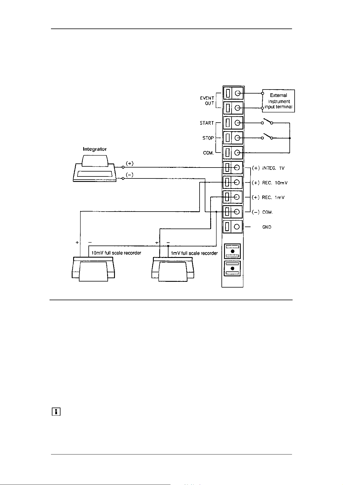
Operating Instructions RF-2000
7 Control from External Equipment
7.1 Connecting External Input and Output Terminals
Terminal name Explanation
EVENT OUT
START Starts this instrument by external contact signals. Time
STOP Stops this instrument by external contact signals. Time
COM. COMMON terminal for START and STOP signal.
(+) INTEG. 1V Signal output terminal connected to integrator (1V full scale) .
(+) REC. 10mV Signal output terminal connected to recorder.
(+) REC. 1mV (10mV full scale, 1mV full scale)
(-) COM. COMMON terminal for INTEG. and REC.
GND Grounding terminal
Please note:
Note)
Outputs signals for relay contact (maximum rating: 50V, 0.1A).
It is turned ON/OFF according to the program or the set value
of EVENT parameter in AUX. FUNC.
program is started by shorting this terminal with COM terminal.
program is stopped by shorting this terminal with COM
terminal.
EVENT OUT terminal is turned ON for several seconds in the
period from powering up until the detector initialization is
completed. Take care so that the external equipment does not
malfunction.
56
Page 59
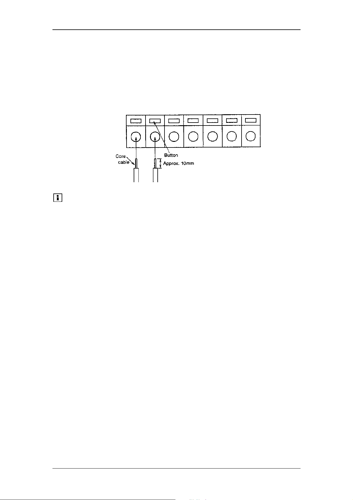
Operating Instructions RF-2000
Wiring
(1) Strip the sheath of the connecting cable for approx. 10mm in length at the
end.
(2) If the core wire is solid, just insert it into the hole of a terminal while pressing
the button above the hole using a small screwdriver or similar tool.
If it is stranded, twist the end well, then insert it into the hole while pressing
the button above the hole using a small screwdriver or similar tool. To
disconnect the cable, also press the button and pull out the cable.
Please note: A signal cable is provided with the RF-2000 as a standard
accessory. In case two or more circuits or terminals shall be
used, prepare cable separately.
To protect the cable from breaking of wire, it is recommended
to use stranded cables.
Cables having a core wire of diameter within the range shown
below may be used.
Solid wire: Ø 0.4-1.0 (AWG 26-18)
Stranded wire: Ø 0.3mm
2
to 0.75mm2 (AWG 22-20)
Element wire diameter: Ø 0.18 at the minimum
57
Page 60
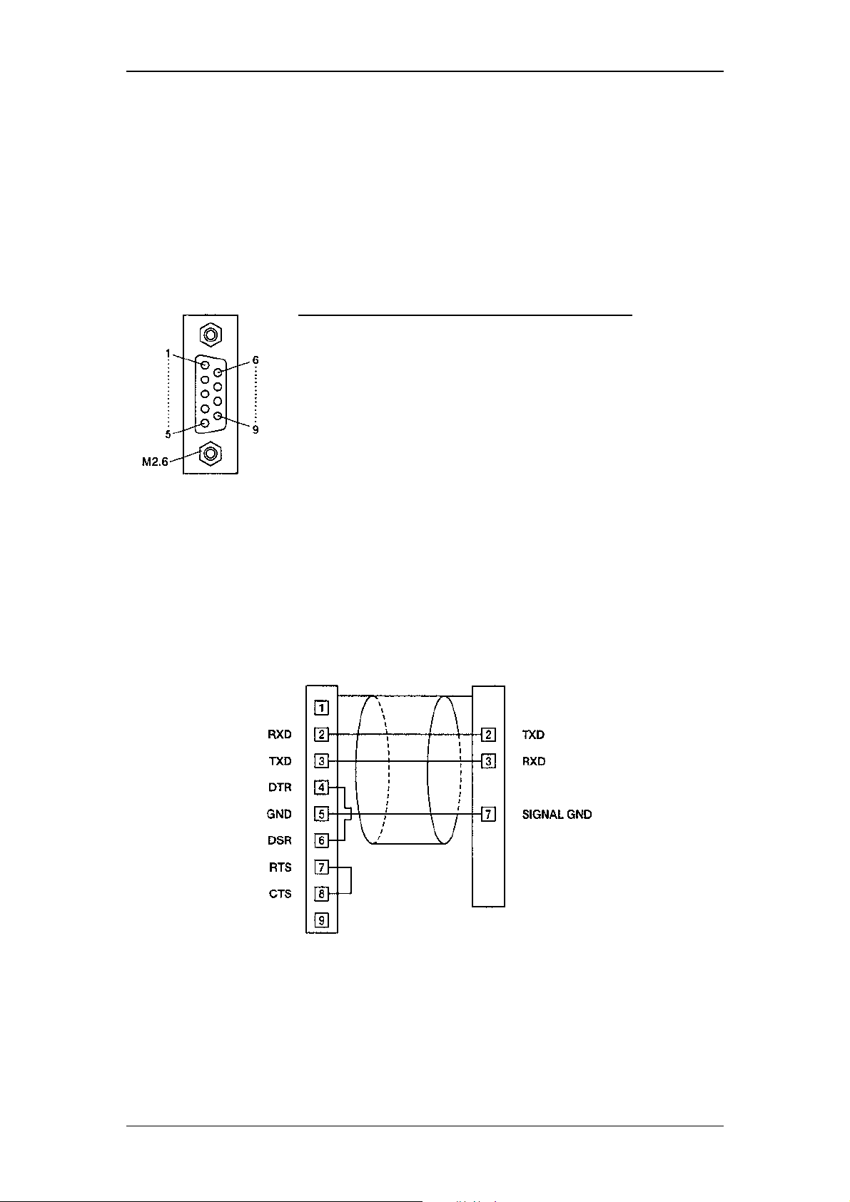
Operating Instructions RF-2000
7.2 Control from External Equipment via RS-232C
An external device or data system such as CHROMELEON can control the RF-2000
using the RS-232C interface. This section explains how to connect the RF-2000 to an
external system and how to operate the RF-2000 using external control.
7.2.1 Connecting external equipment
The pins of RS-232C terminal at the rear panel of the RF-2000 are defined as shown
in the figure below.
9-Pin Female
DSUB type connector
Use the optional RS-232C cable (part no. 8914.0115) for the connection between the
RF-2000 and a PC.
The figure below shows the connection in this cable.
9-pin female DSUB Type
Pin No. Signal name Function
1 FG Frame grounding
2 T x D Output data line
3 R x D Input data line
4 NC Not connected
5 NC Not connected
6 NC Not connected
7 SG Signal grounding
8 NC Not connected
9 NC Not connected
PC side RF-2000 side
9-pin male DSUB type connector
connector
58
Page 61

Operating Instructions RF-2000
7.2.2 Setting parameters and activating the remote control mode
Press the func key (or shift + func key) repeatedly, until the display indicates the
command:
EX(nm) EM(nm) Data
RS232C
Press the Enter key to display the commands for setting the parameters for RS232C.
The commands are shown as follows.
When pressing the func key, the display successively displays the commands in the
following order.
When pressing the shift + func key, the commands are indicated in the reverse
order.
Activating the Remote control mode:
EX(nm) EM(nm) Data
CONNECT
Then press the func key to set the baud rate:
EX(nm) EM(nm) Data
BAUD __
Then press the func key to set the data word size:
EX(nm) EM(nm) Data
DATA BITS __
Then press the func key to set the parity:
EX(nm) EM(nm) Data
PARITY __
Then press the func key to set the stop bit:
EX(nm) EM(nm) Data
STOP BIT __
(1) Activating remote control mode
EX(nm) EM(nm) Data
CONNECT
Press the Enter key. The RF-2000 is is now controlled from the external
equipment via the RS-232C interface.
In the remote control mode, the display of the RF-2000 indicates the
excitation wavelength, the emission wavelength and the emission intensity,
and RF-2000 outputs the analog signals of the emission intensity.
In this mode, any key input is disabled.
Please note:
When turning the power ON again, the remote mode is
activated. To release this mode, press the shift key and the CE
key simultaneously.
59
Page 62

Operating Instructions RF-2000
(2) Setting baud rate
EX(nm) EM(nm) Data
BAUD __
Set value Baud rate
1 300 bps
2 600 bps
3 1200 bps
4 2400 bps
5 4800 bps
6 9600 bps
Enter the desired set value with the numeric key and press the Enter key.
(3) Setting data word size
EX(nm) EM(nm) Data
DATA BITS __
Set value Data word size
7 7 bit communication
8 8 bit communication
Enter the desired set value with the numeric key and press the Enter key.
(4) Setting parity
EX(nm) EM(nm) Data
PARITY __
Set value Parity
0 No parity
1 Odd parity
2 Even parity
Enter the desired set value with the numeric key and press the Enter key.
(5) Setting stop bit
EX(nm) EM(nm) Data
STOP BIT __
Set value Stop bit
0 No stop bit
1 1 stop bit
2 2 stop bits
Enter the desired set value with the numeric key and press the Enter key.
60
Page 63

Operating Instructions RF-2000
7.2.3 Controlling the RF-2000 via CHROMELEON
Important:
Requirements:
• The communications parameters must be correctly set on
the instrument:
Baudrate: 9600
Databits: 7
Parity: None
Stopbits: 1
To enter the parameters, proceed as described in the
previous section.
• The detector must be switched to the remote mode. The
keyboard will then be deactivated. To release the keyboard
lock, simultaneously press the <SHIFT> and <CE> keys for
at least 3 seconds. See the previous section.
After the RF-2000 device driver is correctly activated in the CHROMELEON
Installation Program (usually by Dionex Service), you can control the RF-2000 from
your control panel.
Choose "Command..." from the "Control" menu. Click "Emission" to view the
available commands and variables for the RF-2000. Under "Help", you will see a
description of the currently selected command. If you need further assistance on
specific commands, please press F1 in CHROMELEON to open the CHROMELEON
online Help system. Find the required term via the Index.
Recording Spectra
Spectra cannot be recorded simultaneously with the emission signal. Single spectra
scans are performed instead. During this time, the pump flow should be stopped to
guarantee a stable status in the flow cell of the RF-2000.
The duration of the scans depends on the set scan speed and the scan range. A
scan from 200 to 900 nm with the scan speed "Fast" takes approx. 85 seconds.
The result of a scan is either an emission spectrum or an excitation spectrum. These
spectra are automatically saved in a spectra library. A library by the name RF-
2000.LIB is created in the timebase directory of the local datasource. All RF-2000
spectra are added to this library.
Proceed as follows to scan an emission spectrum:
• Stop the pump flow via the Flow=0 command.
• Then perform the "ScanEmission" command. Depending on when the pump flow
was stopped and when the scan procedure was started, either a background
spectrum or a peak spectrum is saved.
• Perform the analog procedure to determine an optimum excitation value.
Perform the following steps to record a difference spectrum:
• Record a background spectrum as described above.
• Then choose the command "Save Background Spectrum" to save this spectrum
separately in the detector.
• Reset the pump flow to the original value via the command "Flow= ... ". Continue
until the maximum of the peak to detect is reached.
• Stop the pump flow and record a new spectrum.
The two spectra now exist in the RF-2000 spectra library as well as in individual
spectra in two different storage locations within the detector.
• Perform the command "GetSpectraDifference" to receive a difference spectrum.
61
Page 64

Operating Instructions RF-2000
The detector reacts as if a Scan procedure was started. The result of the difference
formation is saved to the RF-2000 spectra library again. This spectrum indicates the
optimum emission or excitation value.
Important:
The basic requirement for forming difference spectra is the
correspondence between the wavelength range defined by the
start wavelength and the end wavelength as well as spectra
type (Excitation or Emission).
PGM-File: Scan Procedure
The following PGM-file allows you to find optimum values for the "Emission"
parameter. Proceed in the same way for the "Excitation" parameter.
-0.1 Pressure.LowerLimit = 0
Pressure.UpperLimit = 400
%A.Equate = "%A"
%A.Type = Automatic
%B.Equate = "%B"
%B.Type = Automatic
%C.Equate = "H2O/MeOH 80/20"
%C.Type = Automatic
%D.Equate = "%D"
%D.Type = Automatic
Flow = 1.000
%B = 0.0
%C = 100.0
%D = 0.0
Emission.ExWavelength = 275
Emission.EmWavelength = 350
Emission.Gain = 1.0
Emission.Response = 0.5
Emission.Sensitivity = Low
Emission.Step = Auto
Emission.Average = On
0.000 Emission.Autozero
Inject
Emission.AcqOn
6.000 ; stop flow
Flow = 1.000
Flow = 0.000
; start scanning
Emission.ScanEmission
; wait for start of scan
Wait Emission.Scanning
; wait for end of scan
Wait Not emission.Scanning
; continue flow
Flow = 0.000
Flow = 1.000
10.000 Emission.AcqOff
End
62
Page 65

Operating Instructions RF-2000
7.2.4 Controlling the RF-2000 via GynkoSoft
Controlling the RF-2000 via the GynkoSoft data system is also possible. The device
driver for the RF-2000 must be installed. The sensitivity can be set to "Low" (default)
and "High" in GynkoSoft. The setting "Medium" is not supported by GynkoSoft.
GynkoSoft supports RF-2000 functions with the exception of the spectra scan
commands, this type of data cannot be recorded or output via GynkoSoft.
63
Page 66
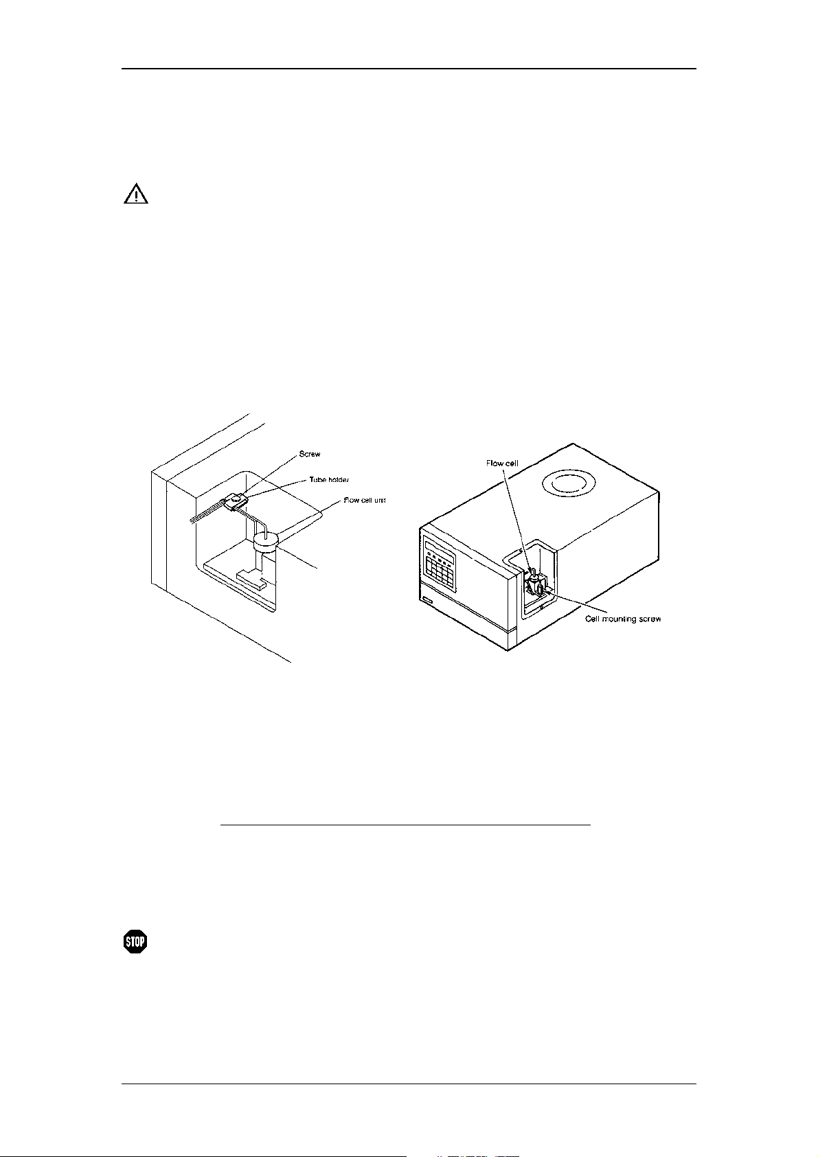
8 Maintenance
8.1 Maintenance of Flow Cell
Operating Instructions RF-2000
Important:
When the xenon lamp is lit, the flow cell is irradiated by the
excitation light beam. Do not stave into the excitation light
beam, while the xenon lamp is lit.
8.1.1 Mounting and dismounting the flow cell
(1) Loosen the screw and take the tubes out of the tube holder.
Loosen the cell mounting screw and pull out the flow cell upward.
(2) To mount the flow cell, pushing the flow cell, set the pins in the pin holes to fix
the position, and tighten the cell mounting screw.
Fasten the tubes with the tube holder and tighten the screw to fix the tubes.
8.1.2 Cleaning the flow cell
Dirty cells and piping may cause phenomena such as an unstable baseline or a large
baseline noise due to pulsation of the solvent delivery pump. In this case, clean the
flow lines with the following procedures.
Item to be prepared Qty
Syringe 1
Adapter 1
Water 100mL
Acetone 50mL
0.1N nitric acid 50mL
Warning:
(1) Deliver acetone from the cell inlet pipe using the syringe and adapter.
(2) Use distilled water to flush the flow lines as in step 1.
(3) Flush the flow lines with 0.1N nitric acid.
Mixing nitric acid with organic solvent may form an explosive
substance. Be extremely careful when handling nitric acid.
64
Page 67
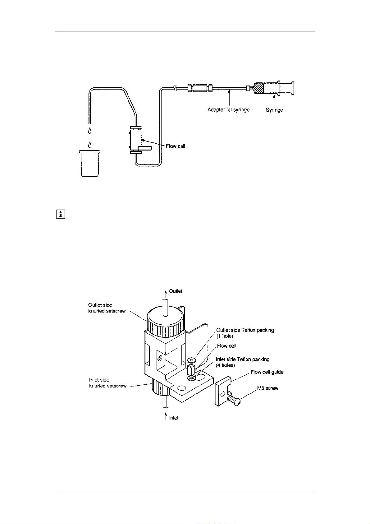
(4) Flush out the nitric acid with distilled water.
(5) Replace with mobile phase. When the mobile phase used for analysis is not
miscible with water, replace the flow lines with acetone and replace it with the
mobile phase.
Operating Instructions RF-2000
8.1.3 Cell disassembling and cleaning
Please note:
(1) Loosen the M3 screw using a screwdriver. Remove the M3 screws and the
flow cell guide.
(2) Loosen the knurled setscrew, then remove the inlet side Teflon packings, the
outlet side Teflon packing and the flow cell.
Carefully handle the flow cell and Teflon packing so as not to
stain or damage them. Careless handling will result in
deterioration of sensitivity or leakage of liquid. For handling,
tweezers coated with resin tube at tips must be used.
(3) Soak the flow cell new inlet side Teflon packing and outlet side Teflon packing
in acetone for cleaning and then clean them again with isopropyl alcohol. If
the flow cell is still stained, use other organic solvents or detergent (Clean 99,
Contaminon, or Exstran etc.) to clean the flow cell. Be sure to remove any
such solvent completely before the installation described below.
(4) Screw in the inlet side knurled setscrew to the bottom.
65
Page 68
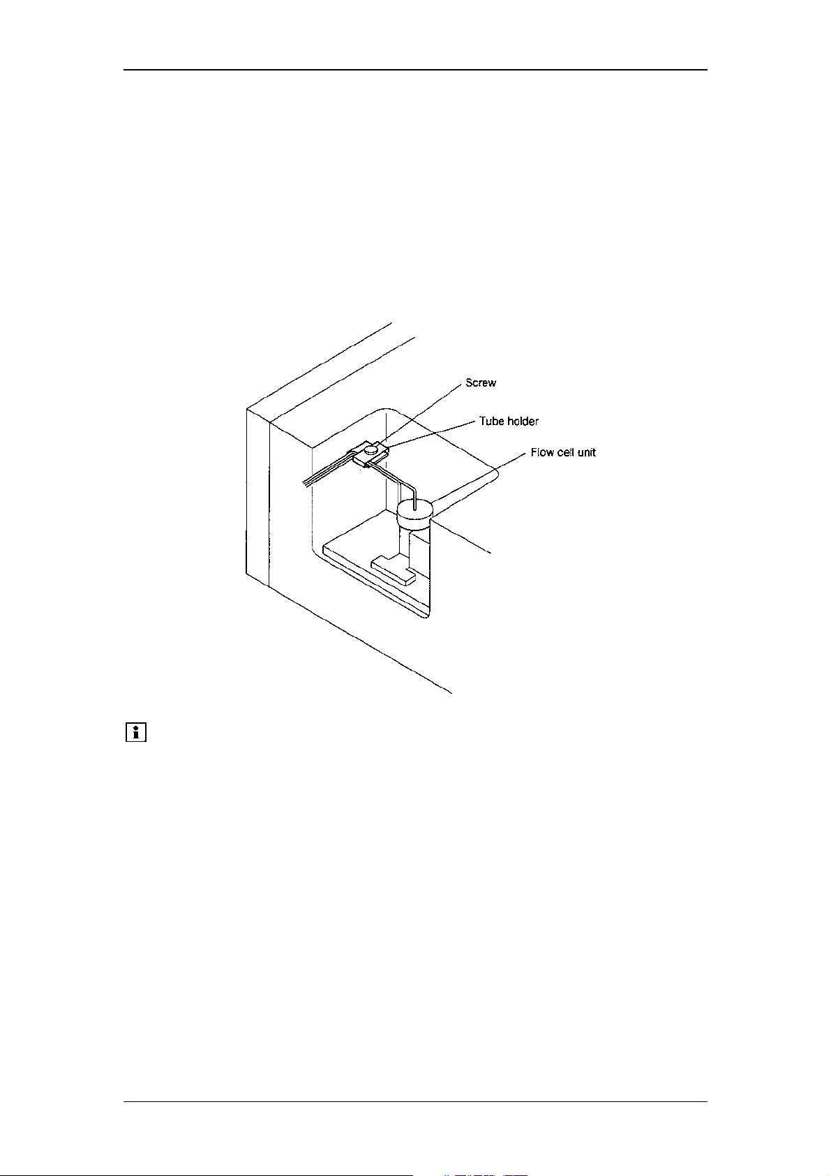
(5) Insert the inlet side Teflon packing (4 holes), flow cell, and outlet side Teflon
packing (1 hole) into the flow cell holder.
Be careful not to set the Teflon packings to wrong position.
(6) Screw in the outlet side knurled setscrew with the degree that no force is
applied to the flow cell, the inlet side Teflon packing and the outlet side Teflon
packing.
(7) Mount the flow cell guide. Tighten the M3 screw using the screwdriver and fix
the flow cell guide.
(8) Tighten the outlet side knurled setscrew by fingers.
(9) Mount the flow cell unit on the instrument main body and fix it by tightening
the cell mounting screw.
(10) Fasten the tubes with the tube holder and tighten the screw to fix the tubes.
Operating Instructions RF-2000
Please note:
1. Do not disassemble components other than the cell,
Teflon packings, cell retaining ASSY, and knurled
setscrews.
2. Be careful not to tighten the knurled setscrews without
setting Teflon packings at both sides of the cell as the
cell may be destroyed.
3. Be sure to use new Teflon packings to reassemble the
unit.
66
Page 69
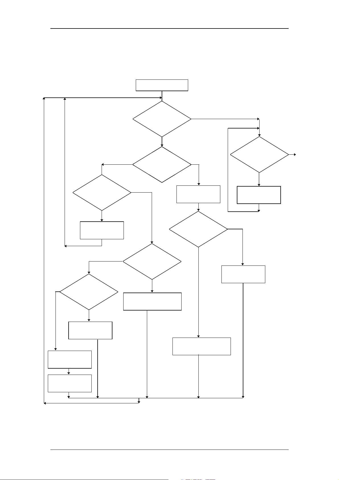
Operating Instructions RF-2000
8.1.4 Liquid leakage from flow cell
A flow chart to find probable causes and counter measures for liquid leakage and
clogging of pipes is shown in the following.
Inspection start
NO
Is the knurled setscrew
loosened?
YES
Tighten the outlet side
knurled setscrew
NO
Is the outlet
Teflon packing
clogged?
Is mobile phase
liquid coming out of the
NO
Is there any
liquid leakage from the cell
assembly?
NO
Is the cell destroyed?
YES
Replace the cell. Refer to
section 7 in the chapter 8.
YES
NOYES
Check for clogging
of the inlet pipe.
Is the inlet pipe clogged?
YES
Is there any
liquid leakage from the
cell assembly?
Tighten the outlet side
knurled setscrew.
NO
Replace the inlet
Teflon packing.
NO
Normal
YES
Replace the outlet
Teflon packing.
Check for clogging
of outlet pipe.
Replace the
outlet pipe.
Remove clogging of the inlet
pipe or replace the inlet pipe.
67
Page 70
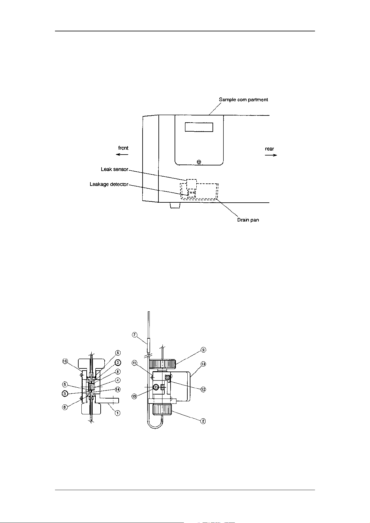
Operating Instructions RF-2000
8.1.5 Countermeasure to LEAK error
If the detector of the leak sensor is wet, even though there is no liquid leakage, LEAK
error may be indicated.
To recover this, open the sample compartment, suck the liquids in the drain pan by
syringe and wipe the liquids on the leakage detector by cotton stick.
8.1.6 Structure of flow cell
Pressure tolerance of the cell is 1960 kPa {20kgf/cm2}
(value in { } is reference.)
If the pressure exceeds this value, the cell may be broken. Be careful when
applying the back pressure etc.
Structure of the flow cell unit:
1 Cell holder
2 Inlet side knurled setscrew
3 Cell retaining ASSY
4 Cell
5 Inlet side Teflon packing
6 Washer
7 Vinyl tube
8 Outlet side Teflon packing
9 Outlet side knurled setscrew
10 Mask
11 Spring
12 Spring
13 Mask
14 Flow cell guide
15 M3 screw (w/spring washer)
8.1.7 Troubles caused by bubbles in the flow cell
(1) Symptoms caused by bubbles
When bubbles are present in the flow cell, the following symptoms appear.
68
Page 71
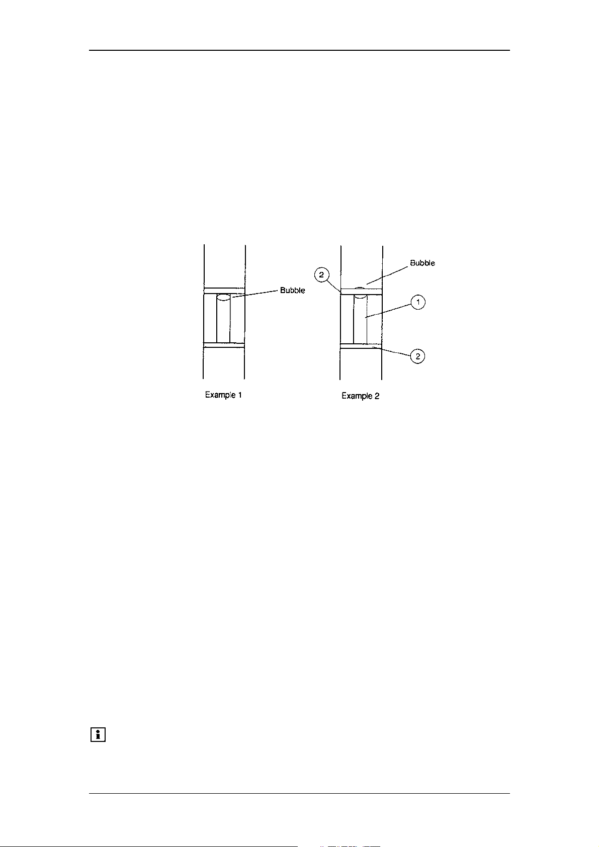
Operating Instructions RF-2000
1) Spiky noises are observed.
2) The base line drifts in one direction and abruptly changes its drift
direction. This symptom appears repeatedly.
3) The base line is not stabilized. Excessive drifts or noises are
observed.
When the end of the flow cell outlet pipe is blocked, the pen moves
greatly.
(2) Checking the flow cell whether bubbles are present inside or not.
Remove the flow cell from the sample compartment, and hold the cell holder
toward a light source (light bulb, fluorescent lamp, etc.) Look into the flow cell
located in the cell holder and check the upper and lower side of the cell
whether any bubbles are present inside or not.
(1) Flow cell (2) Teflon packing
Example : Bubbles in the flow cell
8.1.8 Driving bubbles out and liquid leakage test
(1) Remove the flow cell from the instrument.
(2) Flow methanol or acetonitrile into the flow cell using a syringe or a pump. The
flow rate should be as high as possible.
(3) Ensure that no liquid leaks from the flow cell. If leakage is observed, stop the
liquid flow, and make an appropriate measure according to section "8.1.4
Liquid leakage from flow cell".
(4) Visually check the flow cell light path, and check whether bubbles are present
or not. If any bubbles be trapped inside the cell, stop and open the outlet
tubing lightly and repeatedly with finger to flush away the bubbles.
If bubbles cannot be driven out of the flow cell, drain the liquid from the flow
cell once and fill the liquid into the flow cell again, and check the cell for
bubbles. If bubbles are still present in the flow cell, repeat these procedures
several times.
(5) When no more bubbles are present, mount the flow cell to the equipment.
(6) If bubbles cannot be removed by above procedures, the inner surface of the
flow cell may be stained. Drain the liquid from the flow cell, and then clean the
flow cell according to Sections "8.1.2 Simple Cleaning of flow cell" and "8.1.3
Cell disassembling and cleaning".
Please note:
When a mobile phase which is immiscible with methanol or
acetonitrile is used, replace inside the flow paths with a liquid
which is miscible first. When a buffer is used, flow distilled
69
Page 72

water before replacing the liquid.
8.2 Checking the Xenon Lamp
8.2.1 Note in moving this instrument
Operating Instructions RF-2000
Important:
When moving this instrument, be sure to remove the xenon
lamp and put it in the protective case for the xenon lamp. Pay
special attention in handling a xenon lamp since a small
explosion is occurred by high pressure charged in the xenon
lamp when it is destroyed by an impact. If you touched the
xenon lamp valve by hand, clean it with ethyl alcohol before
lighting.
8.2.2 Service life of xenon lamp
A xenon lamp is consumable. Luminescence point of the lamp may move around or
the lamp may flicker in the course of time. When these phenomena occur, noises in
the baseline become extremely large and measurement is not performed accurately.
Important:
Check the flickering of the lamp according to the following procedure:
(1) Connect a pen recorder to the recorder terminal at the rear of this unit.
(2) Fill distilled water in the flow cell using the provided syringe.
Make sure that no air bubble is there in the flow cell.
(3) Turn on the power of the recorder, and adjust the zero point to zero
accurately.
(4) Set the parameters as follows.
EX : 350nm
EM : 500nm
RANGE : 7 (x64)
SENS : 3 (LOW)
RESPONSE : 2 (0. 5s)
GAlN : 3 (x16)
RATIO : 1 (fixed)
Z WAVE : 1
(5) Press the ZERO key of the RF-2000 to adjust the zero point.
(6) Move the emission wavelength at around 350nm so that the displayed value
for data becomes around 700 ~ 800.
(7) Set the range so that the recorder pen varies in the range of 50 ~ 100 scales.
(8) Set the recorder chart speed to about 10mm/min and record for about 30
minutes.
(9) After completing recording, calculate the noise ratio as shown in the figure.
If the noise ratio is 5% or more, the lamp is at the end of its service life.
Replace it with a new one.
Xenon lamp used for a long time (1000 hours or more) is
dangerous since it may explode. Replace the lamp after using
for the ensured hours (500 hours).
70
Page 73
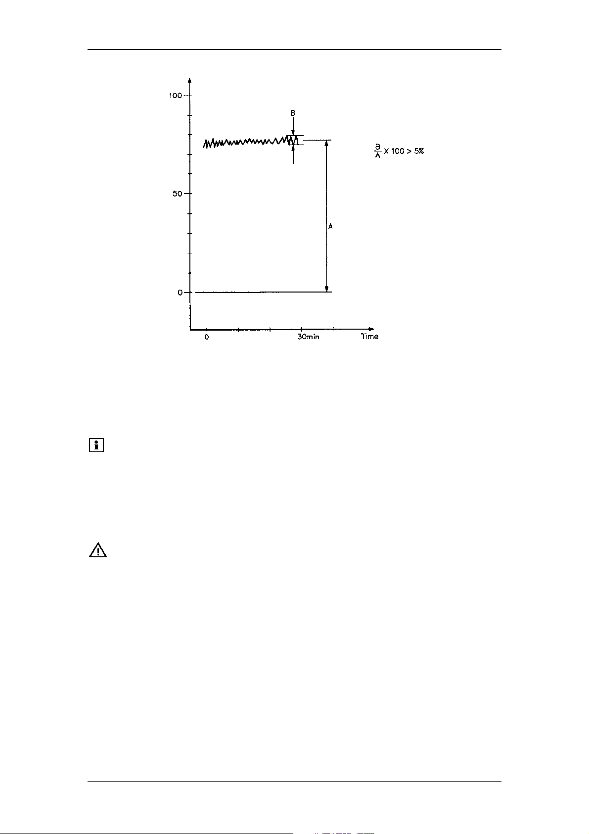
Operating Instructions RF-2000
8.2.3 Operating time of xenon lamp
Operating time of the xenon lamp is displayed in XE TIME in AUX. FUNC. The value
is automatically accumulated while the lamp is lit on. Enter 0 and Enter to reset the
time when replacing the lamp. Operating time of lamp is indicated in the unit of hour.
Please note:
Reset the time only when replacing the lamp.
8.2.4 Replacing procedure for xenon lamp
Replace the xenon lamp following the same procedure as described in section "4.6
Installing the Xenon Lamp" and "4.7 Adjusting the Xenon Lamp Alignment".
Important:
When LAMP of AUX FUNC is set to "0", xenon lamp is turned off with the power still
supplied. (Refer to "5.5.1 AUX FUNC.") The lamp is cooled down in about 30 min.
under this condition. After cooling down of the lamp, turn the power switch OFF, pull
out the power cable and wait for 5 min before replacing the lamp.
Xenon lamp is extremely hot right after turning the power
switch OFF. Wait for more than an hour after turning the power
switch OFF and be certain that the xenon lamp is no longer hot
by opening the light source chamber cover before replacement.
71
Page 74
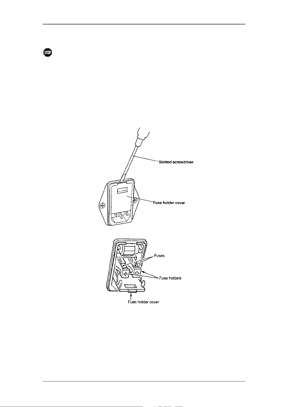
8.3 Replacing the Fuse
Operating Instructions RF-2000
Warning:
Replace the blown fuse according to the following procedure. Be sure to use a fuse
specified in the Accessories and Spare Parts list.
(1) Turn the power switch OFF.
(2) Disconnect the power cable from the power supply connector.
(3) Open the fuse holder cover with a regular screwdriver.
This instrument uses two of the following fuses. Be sure to replace
the fuses of the same type and capacity.
for power supply: 220-240 VAC
Part no. 706.072.0165221
250V 3.15AT
(4) Take out the fuse holder to this side.
(5) After replacing the fuse, push the fuse holder in with the arrow side faced
down.
(6) Close the fuse holder cover until it clicks.
72
Page 75
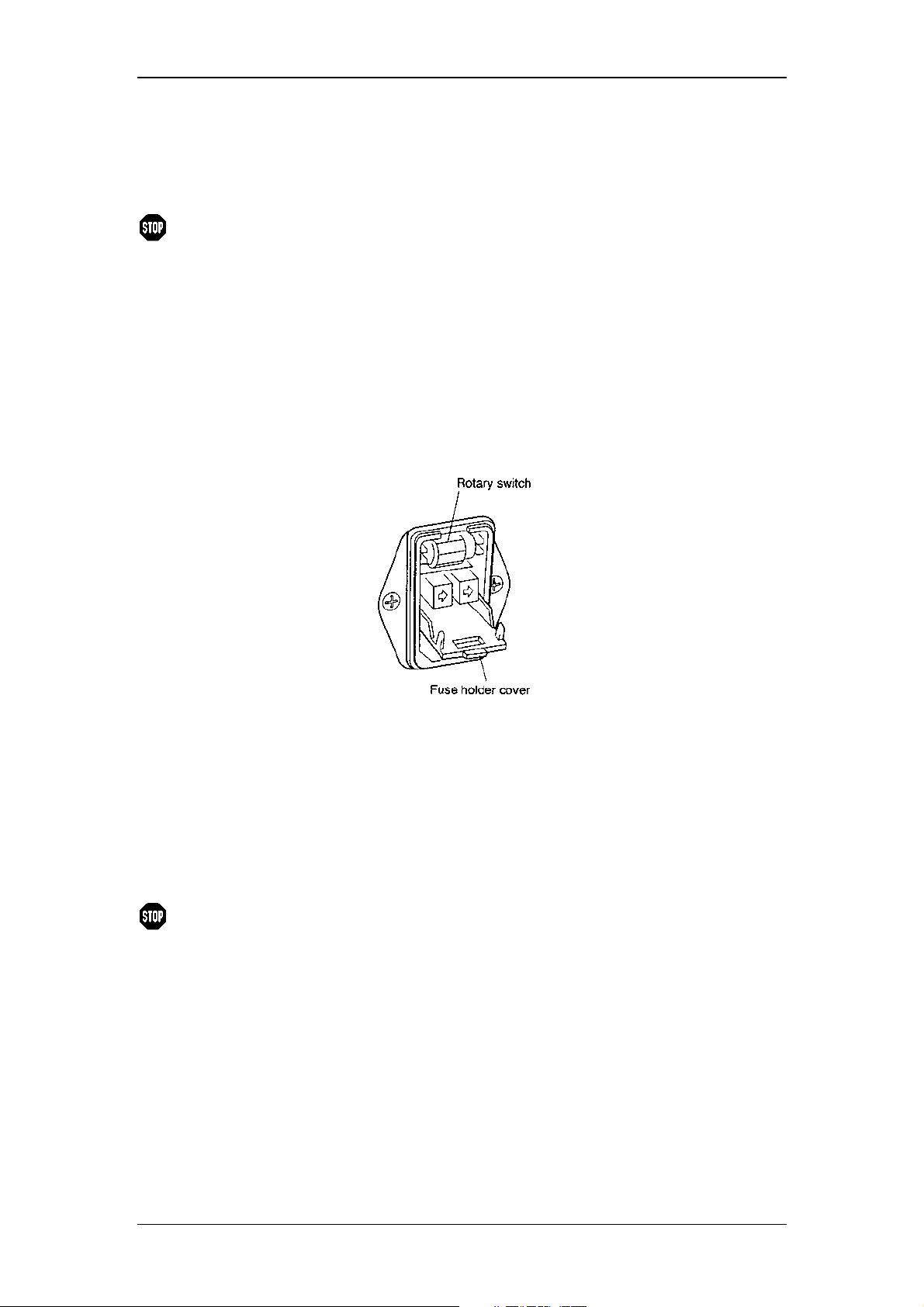
Operating Instructions RF-2000
8.4 Changing the Set Power Supply Voltage
To change the power voltage setting of this unit, it is necessary to change the setting
of the power supply connector unit, of the Xenon lamp power supply and the fuse.
Warning:
Setting of the power supply voltage for this unit should conform
to the operating power supply voltage.
8.4.1 Setting of the power supply connector
(1) Turn OFF the power switch.
(2) Pull out the power supply cable from the power supply connector.
(3) Open the fuse holder cover at the rear of this unit by a slotted screwdriver
(see illustration in the previous section).
(4) Change the rotary switch showing the voltage in the fuse holder as follows.
Power supply voltage Setting of rotary switch
100V±10% 100Va.c
120V±10% 120Va.c
220V±10% 230Va.c
230V±10% 230Va.c
240V±10% 240Va.c
(5) Close the fuse holder cover until a clicking sound is heard.
Warning:
If the power supply voltage is 100 or 120 Va.c, a different fuse
type must be used! Please contact Dionex Service.
73
Page 76
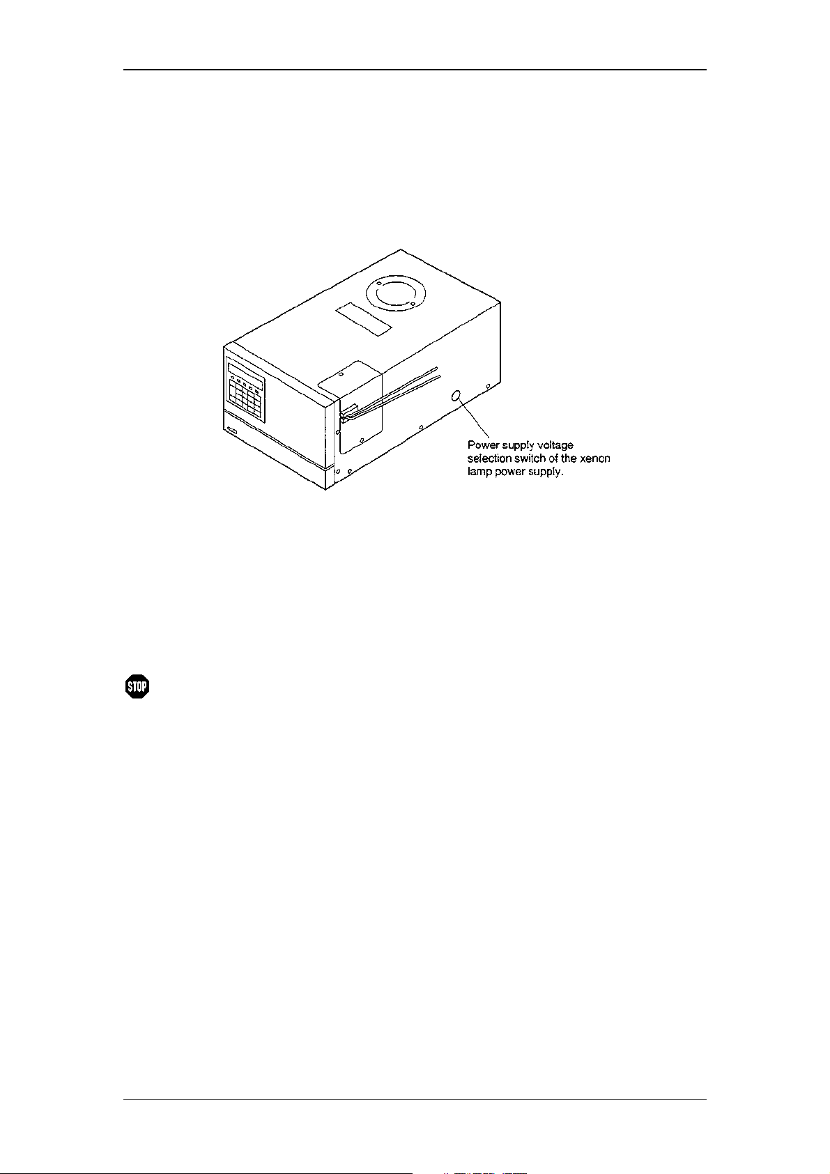
Operating Instructions RF-2000
8.4.2 Setting of the Xenon lamp power supply
(1) Turn OFF the power supply switch.
(2) Remove the rubber lid of the power supply voltage switch of the xenon lamp
located on the right side of this unit.
(3) Conform the selection switch of the xenon lamp power supply to the power
supply voltage as the following table.
Power supply voltage Setting of the xenon lamp
power supply
100V±10% 100V
120V±10% 100V
220V±10% 200V
230V±10% 200V
240V±10% 200V
Warning:
(4) Push in the rubber rid into the hole to seal the switch.
If the power supply voltage is 100 or 120 Va.c, a different fuse
type must be used! Please contact Dionex Service.
8.5 Periodical Cleaning
If the cover or the panel of the unit is stained, wipe out dirt or dust with soft cloth or a
piece of paper. If necessary, use a non-ionic detergent.
74
Page 77
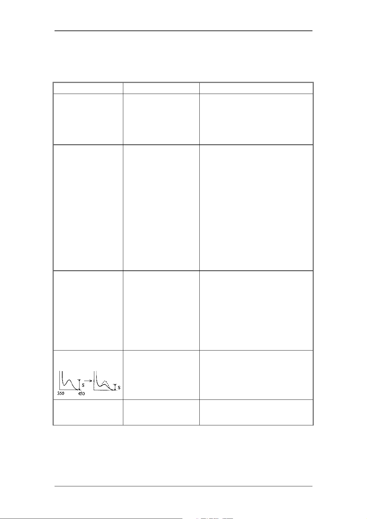
Operating Instructions RF-2000
9 Troubleshooting
9.1 Summary of the Most Frequently Problems
Symptom Probable cause Remedy
1. Power is not
supplied even by
turning the power
switch ON.
Causes other than above
2. Xenon lamp is not lit
on.
Failure of wiring contact Check the connection of high voltage
Lamp is not cooled. Leave the lamp for about 10 minutes to
Power supply for xenon
An overheat error occurs. Contact our service sales office or
3. No signal comes
out.
Fuse for power supply is
blown.
cause.
AUX. FUNC. LAMP is "0". Set the AUX. FUNC LAMP to "1" (light
lamp is defective.
Lamp is not lit. Referring to item 2, check the lamp.
Check the fuse in the fuse holder at the
rear of this instrument and replace if it
is blown.
Contact the
department.
ON). (See "5.5 AUX. FUNC.")
cable connected to the + pole of the
xenon lamp. Be sure to disconnect the
AC cable from the plug socket before
this check. It is very dangerous if the
power is accidentally turned ON.
allow it cool.
Contact the
department.
representatives. (See "9.2 List of Error
messages".)
Dionex Service
Dionex Service
Adjustment of light source
position is considerably
bad.
Measuring conditions are
not set properly.
Causes other than above
causes.
4. Improper S/N value
(Signal level is low.)
Improper light source
Improper installation of
the flow cell
position
Readjust the light source position.
Check the settings of wavelength and
sensitivity.
Contact the
department.
Check that the flow cell is properly
installed in the sample compartment.
(See "8.1.1 Mounting and dismounting
the flow cell")
Readjust the light source position. (See
"4.7 Adjusting the Xenon Lamp
Alignment")
Dionex Service
75
Page 78
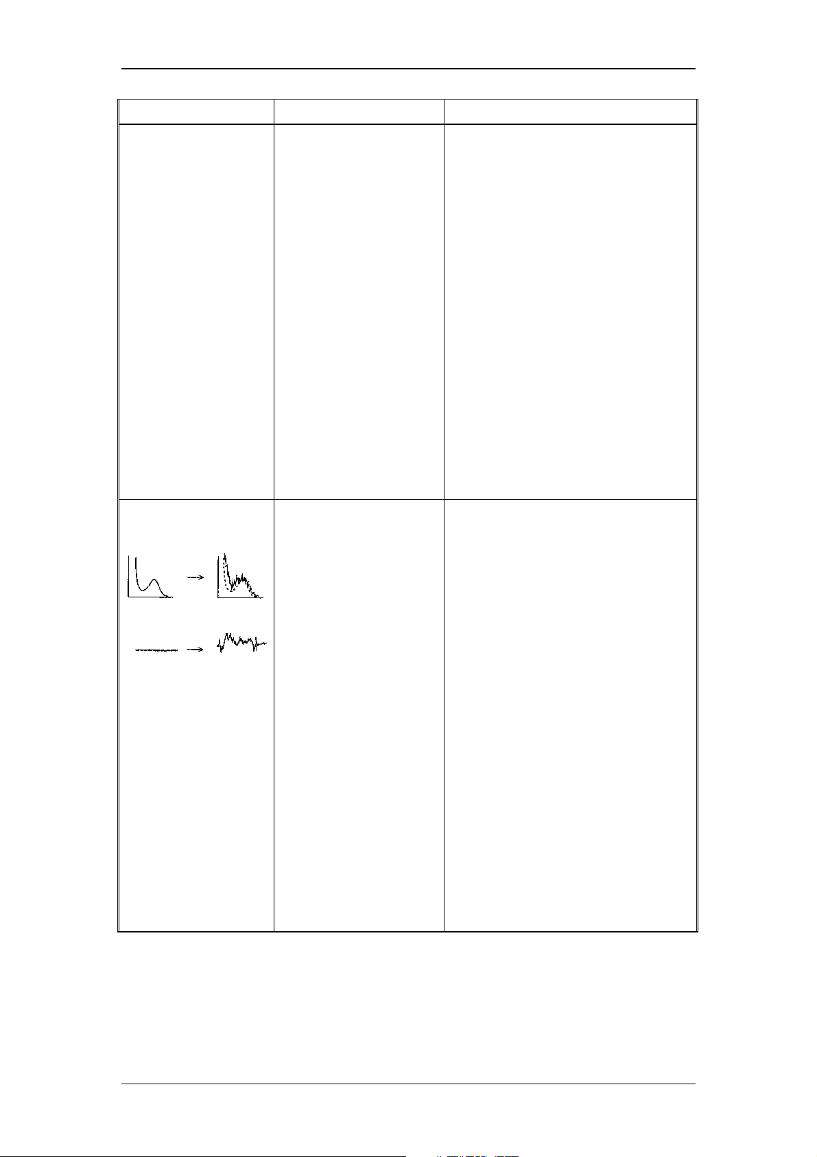
Symptom Probable cause Remedy
Operating Instructions RF-2000
(cont.:)
4. Improper S/N value
(Signal level is low.)
Check that the knurled setscrews are
Replace the packings to new ones.
If the wavelength is out of the specified
Improper sensitivity
Defective-HV board
Causes other than above
5. Improper S/N value
(Noise level is
excessive.)
Bubbles in the flow cell Drive bubbles out of the flow cell. (See
"8.1.8 Driving Bubbles out of Flow Cell
and Liquid Leakage Test")
tightened. (See "8.1 Maintenance of
Flow Cell")
(See "8.1 Maintenance Flow Cell")
Improper wavelength
adjustment
(preamplifier circuit)
causes
Improper installation of
flow cell
Check wavelength.
range, contact our service department
for wavelength adjustment.
Contact our service department for
sensitivity adjustment.
Contact our service department.
Contact our service department.
Check that the flow cell is properly
installed in the sample compartment.
(See "8.1.1 Mounting and dismounting
the flow cell")
Improper light source
Flickering of the xenon
Replace the xenon lamp. (See "4.6
Bubbles in the flow cell Drive bubbles out of the flow cell. (See
Check that the knurled setscrews are
Replace the packings to new ones (See
Causes other than above
position
lamp
causes
Readjust the light source position. (See
"4.7 Adjustment of Xenon Lamp
Alignment")
Check the xenon lamp for flickering.
(See "8.2.2 Service life of xenon lamp")
Installing the Xenon Lamp")
"8.1.8 Driving Bubbles out of the Flow
Cell and Liquid Leakage Test")
tightened (See "8.1 Maintenance of
Flow Cell")
"8.1 Maintenance of Flow Cell")
Contact our service department.
76
Page 79

Symptom Probable cause Remedy
6. Raman peak of
water is not
displayed.
Impurities in water Use new distilled water.
Operating Instructions RF-2000
Stains of the flow cell Clean the cell (See "8.1 Maintenance of
Replace the cell (See "8.1 Maintenance
Bubbles in the flow cell Drive bubbles out of the flow cell. (See
Check that the knurled setscrews are
Improper wavelength Check wavelength.
If the wavelength is out of the specified
Defective M2 mirror Contact our service department for
Causes other than above
7. There is no output at
the recorder
terminal.
Causes other than above
8. "OVER" is displayed Integrator output is over to
Sensitivity setting (SENS)
Causes other than above
Flow Cell")
of Flow Cell")
"8.1.8 Driving Bubbles out of the Flow
Cell and Liquid Leakage Test")
tightened (See "8.1 Maintenance of
Flow Cell")
Replace the packing (See "8.1
Maintenance of Flow Cell")
range, contact our service department
for wavelength adjustment.
cleaning of the mirror.
Contact our service department.
causes
Range is set to 0. Set the range to an appropriate value.
Dionex Service
Dionex Service
cause.
+ side.
is too high. ("OVER" is
still displayed even if
ZERO key is pressed.)
causes
Contact the
department.
Press the ZERO key to adjust zero
point.
Set sensitivity lower (see "5.2.5 Setting
Sensitivity")
Contact the
department.
77
Page 80
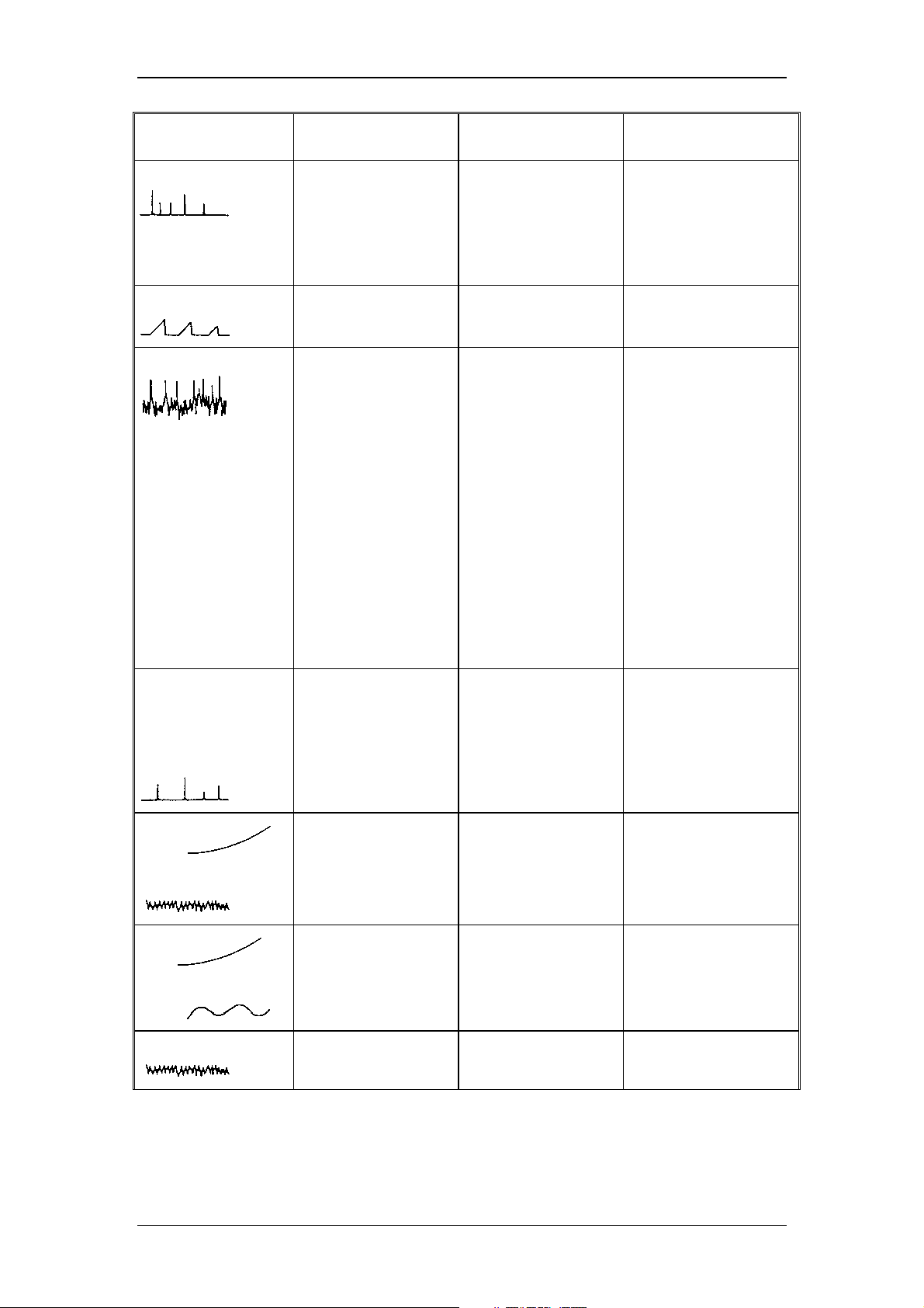
Operating Instructions RF-2000
Symptom Probable cause
Confirmation of
cause
Transient spiking
Bubbles flowing
through the cell
With the flow cell
tubing connected,
remove the cell, and
check it under flow,
check for bubbles or
cell fouling.
Sawtooth baseline
Bubbles flowing
through the cell
Continuous spiking
Bubbles flowing
through the cell/
Bubbles trapped in
the cell
Countermeasures
1) Apply pressure to
the cell outlet side
lightly. Stop or
open the end of
the outlet pipe with
a finger lightly.
"
2) Degas the mobile
phase.
"
3) Clean the cell
interior with
isopropyl alcohol.
Remove the cell
inlet tubing
connector and
force isopropyl
alcohol from the
outlet side with a
syringe. Take care
not to allow air
come in and
connect the inlet
side connector
and flow mobile
phase.
Spiking occurring
at every stroke of
the pump. No
equilibration of
baseline.
Drift
Noise is excessive
Drift
Swell
Noise is excessive.
Bubbles trapped in
the cell
Cell window is
stained.
Impurities in the
mobile phase
Light source Iamp
degradation
" 4) Cell rinsing
"
The drift stops after
stopping liquid
supply.
5) Check the pump,
column, reservoir
and mobile phase
for dust or
impurities.
Check the operating
time of the lamp.
6) Replace the lamp
with a new one.
78
Page 81
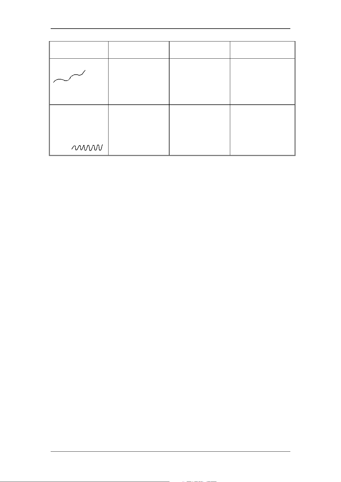
Operating Instructions RF-2000
Symptom Probable cause
Baseline wanders.
Noise occurs
corresponding to
the pump stroke
(when using a
small plunger
pump)
The unit is in the
presence of a
strong air current.
Mobile phase
pulsation
Confirmation of
cause
Countermeasures
7) Change the
location of the
instrument or
place it in a
protective
environment.
8) Eliminate
pulsation from the
pump. Use a
damper.
79
Page 82

Operating Instructions RF-2000
9.2 List of Error Messages
9.2.1 Errors which cannot be reset
Turn the power of the instrument OFF and turn it ON again. If the error message
persists, turn OFF the power and contact your Dionex Service Representative.
(1) RAM error
It is displayed when something is wrong with the RAM.
EX(nm) EM(nm) Data
RAM FAILURE
(2) ROM error
It is displayed when something is wrong with the ROM.
EX(nm) EM(nm) Data
ROM FAILURE
(3) OVERHEAT error
It is displayed when the temperature in the instrument is abnormally high. If
this error occurred, the Xenon lamp is not lit even if the power is turned ON
again.
To repair this instrument and to cancel this error, contact our sales office or
representatives.
9.2.2 Errors which can be reset
Alarm sound stops by pressing CE and the next step is proceeded.
(1) Set value loss error
It is displayed if the parameters or the time program set previously are lost at
power on. Press CE and the instrument becomes operational. Set parameters
again.
EX(nm) EM(nm) Data
NOT PROTECTED
(2) File type error
It is displayed when the spectrum type or wavelength range for the file 0 and
those for the file 1 or 2 which is to be output in SPC PLOT are different.
EX(nm) EM(nm) Data
ERR FILE TYPE
80
Page 83

(3) No file error
It is displayed when there is no data in the file in SPC PLOT or there is no
data in the file 0 when the file 1 or 2 is specified (subtracted spectrum output).
EX(nm) EM(nm) Data
DATA NOT EXIST
(4) Peak detection error
It is displayed when the Raman peak of the distilled water is not detected for
S/N CHECK.
See item 6 of the table of "9 Troubleshooting" to solve this problem.
EX(nm) EM(nm) Data
NO PEAKS
(5) EEPROM error
It is displayed when something is wrong with the EE_PROM.
EX(nm) EM(nm) Data
EE-PROM FAILURE
Operating Instructions RF-2000
(6) Home position error
It is displayed when the motor home position sensor does not operate
properly.
EX(nm) EM(nm) Data
ERR EX HOME POS1
EX(nm) EM(nm) Data
ERR EX HOME POS2
EX(nm) EM(nm) Data
ERR EM HOME POS1
EX(nm) EM(nm) Data
ERR EM HOME POS2
Excitation motor origin (coarse)
Excitation motor origin (fine)
Emission motor origin (coarse)
Emission motor origin (fine)
81
Page 84
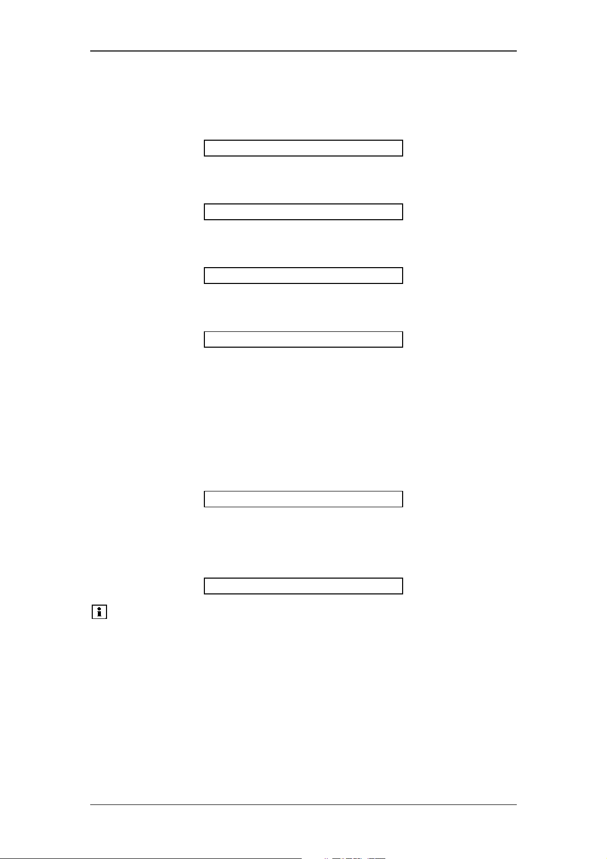
(7) Wavelength calibration data error
It is displayed when the wavelength calibration data entered in the unit is
abnormal.
EX(nm) EM(nm) Data
ERR EX OFFSET
EX(nm) EM(nm) Data
ERR EX W TABLE
EX(nm) EM(nm) Data
ERR EM OFFSET
EX(nm) EM(nm) Data
Operating Instructions RF-2000
Excitation side
Excitation side
Fluorescence side
(8) LAMP error
It is displayed when the xenon lamp is not lit.
• To lit the xenon Lamp again, operate the following procedure. Turn the
power OFF and then turn the power ON.
• Set the "LAMP" parameter in additional functions to "1".
• If this error message is displayed again, refer to "8.2 Checking the Xenon
Lamp" and "9 Troubleshooting".
EX(nm) EM(nm) Data
(9) LEAK error
It is displayed when leak of liquid from the flow cell is detected. See "8.1
Maintenance of the Flow Cell".
EX(nm) EM(nm) Data
Please note:
ERR EM W TABLE
Fluorescence side
ERR LAMP
ERR LEAK
If the detector of the leak sensor is wet, even though there is
no liquid leakage, LEAK error may be indicated.
To recover this, refer to "8.1.5 Countermeasure to LEAK error".
82
Page 85

Operating Instructions RF-2000
9.2.3 Error which can be reset with the shift + CE key.
(1) Rejecting key input
When "CLOSE KEY" of the additional function is set or RF-2000 is controlled
from a external equipment via RS-232C, any key input is rejected.
To release these settings, press the CE key and the shift key simultaneously.
(Refer to "5.5 Additional Functions" and "7.2 Control from external equipment
via RS-232C".)
EX(nm) EM(nm) Data
CLOSED KEY
83
Page 86

Operating Instructions RF-2000
10 Specifications
Light source: 150W xenon lamp
Light source chamber: Ozone self dissolving type lamp house
Monochromators:
Number of grooves: 900 lines/mm
Wavelength range: 200~650nm and 0 order
Bandwidth: 15nm for both excitation and emission sides
Wavelength accuracy: ±2nm
Wavelength repeatability: ±0.2nm
Wavelength scanning speed:
Wavelength moving speed: Approx. 15,000nm/min
Detector:
Measuring method:
Time constant: 0.1, 0.5, 1.5and 3s, 4 steps.
Ion brazed holographic concave diffraction
grating monochromators F/2. 4 for both excitation
and emission sides
SUPER, FAST, MEDIUM and SLOW, 4 steps
SUPER: Approx. 3,000nm/min
FAST: Approx. 600nm/min
MEDIUM: Approx. 120nm/min
SLOW: Approx. 24nm/min
Signal side: Photomultiplier tube
Monitor side: Photodiode
Ratio compensation system with
monochromatic light monitoring.
Sensitivity:
Gain:
Range:
Output terminals:
Input terminals: Contact signal input (START input, STOP input)
Cell:
Communication: Controllable by CHROMELEON via RS-232C
Display unit: Fluorescent display tube
Measuring function:
HIGH, MED and LOW, 3 steps
(sensitivity difference is approx. 32 times)
x1, x4, and x16, 3 steps
(approx. 1 time, 4 times, and 16 times)
1/∞ (0mV), x1, x1/2, x1/4, x1/8, x1/16, x1/32,
x1/64, x1/128, x1/256
Recorder: 1mV, 10mV
Integrator: 1V/FS
Contact signal output (EVENT OUT output)
12µl square quarts flow cell,
pressure tolerance 1.96Mpa
{20kgf/cm
* Monitor function
Auto zero, Base line shift
* Time program function
Up to 32 steps can be programmed.
* Wavelength scanning function
Excitation and Emission wavelength scanning
Differential spectrum Plot output
2
} (figure inside { } is reference.)
84
Page 87
Operating Instructions RF-2000
Filing:
Dimensions: 260 (width) x 520 (depth) x 205 (height) mm
Weight: Approx. 17kg
Power supply:
Power consumption: 350VA
Operating temperature range: 4 ~ 35°C
Operating humidity range:
S/N:
* Measurement condition
One measurement condition can be stored.
* Time program
One time program can be stored.
* Spectrum
Three spectra can be stored.
(However, they are not backed up when the
power is turned OFF.)
AC 100V±10%, 120V±10%, 220V ±10%,
230V±10%, 240V±10% 50, 60Hz
45 ~ 80% (However, humidity should be 70% or
below when the temperature is 30°C or higher.)
S/N at the Raman peak of distilled water is 300
or higher. (when EX = 350nm and RESPONSE =
1.5s.)
85
Page 88

Operating Instructions RF-2000
11 Standard Accessories
Category Description Part No. Qty
Parts
Consumable parts
Tools
Other
Signal cable 706.228.3411091 1
Power cable (for 220 ~ 240V) 706.071.6081406 1
RS-cable 8914.0115 1
RS-adapter 8914.0110 1
Syringe 706.046.00001 1
Syringe adapter 706.204.01647 1
Male nut PEEK 706.228.18565 4
Male to male union 1.6C 706.228.1600403 2
Tefzel tube (1.6 x 0.3, 2m) 706.228.1849506 1
SUS tube (1.6 x 0.3, 0.5m) 706.228.2230500 1
Drain tube 706.016.3135002 1
150W xenon lamp 5057.1000 1
Fuse3.15A (for 220 ~ 240V) 706.072.0165221 2
Teflon packing inlet (3 pcs) 706.228.3413781 2
Teflon packing outlet (3 pcs) 706.228.3413681 2
Screwdriver 1
RF-2000 Operating Instructions 5820.5750 1
Certificate of compliance 1
Label Ver.3 1
Important:
When carrying out maintenance, be sure to use the parts
described in the sections 10 and 11. Normal function of the
system is not guaranteed when other parts are used.
12 Replacement Parts
Description Part No. Remarks
150W xenon lamp 5057.1000 Light source
Cell for LC fluorescence
monitor
Inlet side Teflon packing 706.228.3413781 Part for flow cell (3 pieces)
Outlet side Teflon packing 706.228.3413681 Part for flow cell (3 pieces)
706.200.66504 Part for flow cell
86
 Loading...