

Dionex P680A HPG Quick Installation Manual

P680 HPLC Pump System
Quick Installation Guide
High Pressure Gradient Version
June 2004 rev. 03 Page 1
© 2004 Dionex

This Quick Installation Guide explains the basic installation steps for a P680A HPG highpressure gradient pump system. For additional information, please consult the operating
instructions for the P680 HPLC Pumps.
1. Preparation
Bring the pump to a moderate temperature for four hours to allow any condensation that
might have occurred during transit to evaporate. Do not connect the pump to the mains during
this period. If it is obvious that condensation did not evaporate completely, continue to warmup the pump (which is not connected to the mains) until the condensation is completely gone.
Place the pump on a firm and level surface that is free of vibration. Make sure that the surface
is resistant to solvents. Avoid locations with extreme changes in temperature (such as direct
sunlight or drafts) and high air humidity.
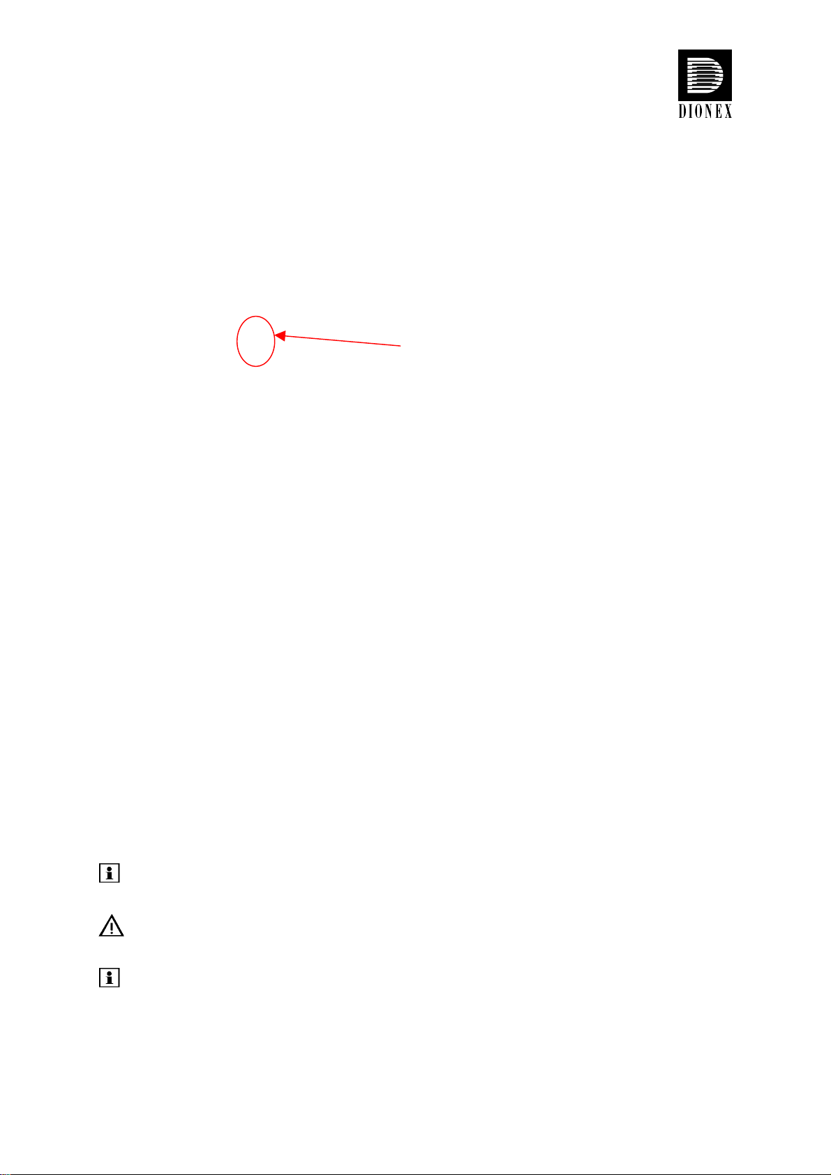
2. Remove the caution label
You may remove the “caution” label
from the pump's enclosure.
Important: The pump is primed with 2-propanol. During initial operation of the
pump, make sure that the solvents used are miscible with
2-propanol. Otherwise, follow the appropriate intermediate steps.
June 2004 rev. 03 Page 2
© 2004 Dionex
3. Connect the eluent tube to the solvent bottle
The bottle caps have five holes. Four holes are capped by default (white caps), one hole is
open for the eluent tube. A retaining guide holds the tubing in place.
Guide the eluent tube through the retaining
guide and into one of the five holes in the
bottle cap.
Retaining guide
Place the eluent frit on the end of the tube,
place the complete assembly into the bottle,
and hand-tighten the bottle cap.
Please note: To exchange the tubes, remove the frit first, then the eluent tube, and then
the retaining guide.
Important: To draw solvents from the solvent bottles, use only eluent tubes with filter
frits. This prevents contamination of the HPLC system.
Please note: Regularly check the frits for permeability. Especially when working with
aqueous solvents, algae and other microorganisms can grow on the frits
and clog them. Therefore, exchange the solvents at regular intervals. Rinse
the bottles thoroughly before using them again. Replace the frits as
necessary.
June 2004 rev. 03 Page 3
© 2004 Dionex
4. Place the SOR-100 Solvent Rack on top of the
pump
The SOR-100 Solvent Rack fits on top of
the P680.
For safety reasons, place the eluent
bottles on the tray on top of the pump.
5. Connect the SOR-100 with the P680
Please note: The pictures below show a 6-channel degasser. For a P680A HPG-2 with two
eluent lines, a solvent rack with a 2-channel degasser (part no. 5030.9210) is sufficient. The
SOR-100A-2 is shipped with one 1-liter eluent bottle, one 2-liter eluent bottle, appropriate
tubing, and bottle caps.
For a P680A HPG-4 with integrated solvent selector valves, the SOR-100A-4 Solvent Rack
with 4-channel degasser (part no. 5030.9220) is the appropriate choice. The SOR-100A-4 is
shipped with two 1-liter eluent bottles, two 2-liter eluent bottles, appropriate tubing, and
bottle caps.
The SOR-100 fits on top of the P680. Open the
SOR-100 by tilting the front panel upward.
June 2004 rev. 03 Page 4
© 2004 Dionex
Pull the tray with the degassing chambers
toward you.
 Loading...