

Page 1

LC20 CHROMATOGRAPHY ENCLOSURE
OPERATOR’S MANUAL
© 1993 Dionex Corporation
Document No. 034859
Revision 02
September 1993
Page 2

© 1993 Dionex Corporation
All rights reserved worldwide
Printed in the United States of America
This publication is protected by federal copyright law. No part of this publication
may be copi ed or distri buted, tr ansmitte d, tran scribe d, stor ed in a r etrieval sy stem,
or transmitted into any human or computer language, in any form or by any means,
electronic, mechanical, magnetic, manual, or otherwise, or disclosed to third parties
without the express written permission of Dionex Corporation, 1228 Titan Way,
Sunnyvale, California 94088-3603.
DISCLAIMER OF WAR RANTY AND LI MITED WARRANTY
THIS PUBLICATION IS PROVIDED “AS IS” WITHOUT WARRANTY OF
ANY KIND. DIONEX CORPORATION DOES NOT WARRANT,
GUARANTEE, OR MAKE ANY EXPRESS OR IMPLIED
REPRESENTATIONS REGARDING THE USE, OR THE RESULTS OF THE
USE, OF THIS PUBLICATION IN TERMS OF CORRECTNESS,
ACCURACY, RELIABILIT Y, CURRENTNESS, OR OTHERWISE.
FURTHER, DIONEX CORPORATION RESERVES THE RIGHT TO REVISE
THIS PUBLICATION AND TO MAKE CHANGES FROM TIME TO TIME
IN THE CONTENT HEREIN WITHOUT OBLIGATION OF DIONEX
CORPORATION TO NOTIFY ANY PERSON OR ORGANIZATION OF
SUCH REVISION OR CHANGES.
TRADEMARKS
DX-LAN, Self-Regen eratin g Suppr essor, SRS, and The rmoFlareare
trademarks of Dionex Corporation.
Teflon and Tefzel are registered trademarks of E.I. du Pont de Nemours and
Company.
PRINTING HISTORY
Revision 01, August 1993
Revision 02, September 1993
Page 3

1
2
Contents
•
Introduction
1.1 Ov ervie w . . . . . . . . . . . . . . . . . . . . . . . 1-3
1.2 Ab out T his Manua l . . . . . . . . . . . . . . . . . 1- 3
1.3 Product Saf ety Information . . . . . . . . . . . . . 1-4
•
Description
2.1 Ov ervie w . . . . . . . . . . . . . . . . . . . . . . . 2-3
2.2 Front Panel . . . . . . . . . . . . . . . . . . . . . . 2-3
2.2.1 Rheodyn e In jection Valve . . . . . . . . . 2-3
2.3 Inte ri or Layout . . . . . . . . . . . . . . . . . . . 2-4
2.3.1 Component Panel . . . . . . . . . . . . . 2-5
Doc. 034859 -0 2 9/93
2.3.2 Rheodyn e In jection Valve . . . . . . . . . 2-6
2.3.3 Self-Regenerating Suppressor . . . . . . . 2-7
2.3.4 Leak Sensor . . . . . . . . . . . . . . . . 2-7
2.3.5 Separator Columns . . . . . . . . . . . . 2-7
2.3.6 Guard Columns . . . . . . . . . . . . . . 2-7
2.3.7 Column Select V alve . . . . . . . . . . . . 2-8
2.3.8 Detector C ells . . . . . . . . . . . . . . . 2-1 1
2.3.9 DS3 Detection Sta bilizer (Optional) . . . 2-11
2.4 Rear Panel . . . . . . . . . . . . . . . . . . . . . . 2-12
2.4.1 Cell Cables . . . . . . . . . . . . . . . . . 2- 13
2.4.2 Waste Line . . . . . . . . . . . . . . . . . 2-13
i
Page 4

Contents
3
4
2.4.3 So lenoid Interfa ce . . . . . . . . . . . . . 2-13
•
Service and Ma intenance
3.1 Routine Operation . . . . . . . . . . . . . . . . . . 3-3
3.1.1 Sample Loading . . . . . . . . . . . . . . 3-4
3.2 Shutdown . . . . . . . . . . . . . . . . . . . . . . 3-7
3.3 Routine Maintenance . . . . . . . . . . . . . . . . 3-7
•
Troubleshooting
4.1 Liquid Lea ks . . . . . . . . . . . . . . . . . . . . . 4- 3
4.2 Excessive System Backpressure . . . . . . . . . . 4-4
5
4.3 Inopera tive Column Sele ct Valve . . . . . . . . . 4-5
4.4 Column Select Valve Air Leaks . . . . . . . . . . 4-5
4.5 Peak Ghosting . . . . . . . . . . . . . . . . . . . . 4-6
4.6 Non-Repr oducible Peak Heig ht or Retention
Tim e . . . . . . . . . . . . . . . . . . . . . . . . . 4-6
4.7 Abnormal Retention Time or Selectivity . . . . . 4-6
•
Service
5.1 Introduc tion . . . . . . . . . . . . . . . . . . . . . 5-3
5.2 Tube Fitting Installation . . . . . . . . . . . . . . 5-3
5.3 Restriction in the Hydraulic System . . . . . . . . 5-4
5.4 Injectio n or Column Select Va lve Liquid Leaks . 5-4
5.5 Column Select Valve Air Leaks . . . . . . . . . . 5-5
ii
Doc. 034859- 02 9/93
Page 5

A
B
Contents
5.6 Cleaning the Column Select Valve Slider . . . . . 5-6
5.7 Rep lacing Colum n Select Va lve Port Face . . . . 5-9
5.8 Servicing the Rheodyne Injection Valve . . . . . 5-9
•
Specifications
A.1 Environmental . . . . . . . . . . . . . . . . . . . . A-3
A.2 Ph ys ical . . . . . . . . . . . . . . . . . . . . . . . A-3
A.3 Hydraulics . . . . . . . . . . . . . . . . . . . . . . A-3
A.4 Insulation . . . . . . . . . . . . . . . . . . . . . . A-4
•
Installation
B.1 Facilities Required . . . . . . . . . . . . . . . . . B-3
B. 2 Inst allation Ins tr uctions . . . . . . . . . . . . . . . B-4
B. 2. 1 Stac king Modules . . . . . . . . . . . . . B-4
B. 2. 2 Waste Lines . . . . . . . . . . . . . . . . . B-5
B.2.3 Leak Control . . . . . . . . . . . . . . . . B-6
B.2.4 Liquid Line C onne ctions . . . . . . . . . B-6
B. 2. 5 Detector C ells . . . . . . . . . . . . . . . B-9
B.2.6 Column Installation . . . . . . . . . . . . B-12
B.2.7 SRS Installation (Optional) . . . . . . . . B-13
B.2.8 Solenoid Valve Connections
to the Pump . . . . . . . . . . . . . . . . B-14
Doc. 034859 -0 2 9/93
iii
Page 6

Contents
iv
Doc. 034859- 02 9/93
Page 7

1 • Introduction
1.1 Ov ervie w . . . . . . . . . . . . . . . . . . . . . . . 1-3
1.2 Ab out T his Manua l . . . . . . . . . . . . . . . . . 1- 3
1.3 Produc t Safety Information . . . . . . . . . . . . . 1-4
Doc. 034859 -0 2 9/93
1-1
Page 8

LC20 Chromatography Enclosure
1-2
Doc. 034859- 02 9/93
Page 9

1 • Introduction
1.1 Overview
The LC20 Chromatog raphy Enclosure is an integral part of the
Dionex DX 500 Chr omatography Systems. It can house the
following system components, which must be ordered separately or
as part of anothe r module: Separator colu mns, optional guard
columns, SRS (Self-Regenerating Supp ressor), DS3 Detection
Stabilizer, and detector cell(s) for the ED40 Electrochemical
Detector and CD 20 Conductivity Detector.
The LC20 is available in two co nfigurations, depending o n
the type of injection valve installed:
•
LC30, PEEK automated inje ction valve (P/N 044088)
•
LC3 0, stainle ss steel automated injection valve (P/N 044171)
1.2 About This Manual
This manual describes the operation, mainte nance, and us e of the
L20 Chromatography E nclosure.
Chapter 1, Introduction, introduces the product a nd conventions
used in the manual, a nd provides safety information.
Chapter 2, Description, is a descriptio n of the physica l aspects of
the LC20 Chromato graphy Enclosure, followed by a functional
description of the operating features.
Chapter 3, Operation and Maintenance, discusses th e operating
features and routine maintenance.
Chapter 4, Troubleshooting, provides step-by -step procedures to
isolate problems and lists possible causes.
Chapter 5, Service, presents step-by-step p rocedures to perf orm
service an d parts replacemen t routines.
Doc. 034859 -0 2 9/93
1-3
Page 10
LC20 Chromatography Enclosure
Appendix A Specifications contains the LC2 0 specifications .
Appendix B, Installation, describes the installation a nd interface
necessary to place the LC20 i nto operation.
1.3 Product Safety Information
This instrument was designed in conformanc e with the safety
requirements set forth in IEC 1010 Safety R equirements for
Electrical Equipment for Measurement, Control, and Laboratory Use.
Section of this manual are flagged with key words and symbols to
denote the natu re of potential haza rds. These safety directives apply
to all operators an d service personnel.
The following safety reference symbols are marked in the instrument
and this manual where nec essary to alert the operator.
Indicates a potential hazard to the operator, or
damage to the instrument o r other property.
Example: Overtightening valve bolts may break them
off.
1-4
Doc. 034859- 02 9/93
Page 11

2 • Description
2.1 Overview . . . . . . . . . . . . . . . . . . . . . . . 2-3
2.2 Front Panel . . . . . . . . . . . . . . . . . . . . . . 2-3
2.2.1 Rheodyne Injection Valve . . . . . . . . . 2-3
2.3 Interior Layout . . . . . . . . . . . . . . . . . . . 2-4
2.3.1 Component Panel . . . . . . . . . . . . . 2-5
2.3.2 Rheodyne Injection Valve . . . . . . . . . 2-6
2.3.3 Self-Regenerating Suppressor . . . . . . . 2-7
2.3.4 Leak Sensor . . . . . . . . . . . . . . . . 2-7
2.3.5 Separator Columns . . . . . . . . . . . . 2-7
2.3.6 Guard Columns . . . . . . . . . . . . . . 2-7
2.3.7 Column Select V alve . . . . . . . . . . . . 2-8
2.3.8 Detector Cells . . . . . . . . . . . . . . . 2-11
2.3.9 DS3 Detection Stabilizer (Optional) . . . 2-11
Doc. 034859 -0 2 9/93
2.4 Rear Panel . . . . . . . . . . . . . . . . . . . . . . 2-12
2.4.1 Cell Cables . . . . . . . . . . . . . . . . . 2-13
2.4.2 Waste Line . . . . . . . . . . . . . . . . . 2-13
2.4.3 Solenoid Interface . . . . . . . . . . . . . 2-13
2-1
Page 12

LC20 Chromatography Enclosure
2-2
Doc. 034 859-02 9/93
Page 13

2 • Description
2.1 Overview
Eluent from the grad ient pump enters the R heodyne injection valve
port inside the enclosure. From the inje ction valve, eluent and
sample flow through the g uard column (if used ), the separator
column, the supp ressor or other post-column device, and finally
through the detec tor cells.
The LC20 may be configured for optional dual-channel opera tion. It
will then include a secon d Rheodyne injection valve and component
panel. There is eno ugh tubing in th e LC20 Ship Kit (P/N 046 300) to
plumb two systems.
The LC20 do es not req uire power. Internal compon ents are operat ed
by the GP40/IP20 p ump.
2.2 Front Panel
The front panel of the enclosur e is the door. It contains access to
one or two Rheodyne injection valves.
2.2.1 Rheodyne Injection Valve
Doc. 034859 -0 2 9/93
The Rheodyne injection valve is mounted on th e component
panel in a manner that allows its control knob to extend
through the fron t door for acce ss. If the LC20 is configured
as a dual-chan nel module, a second Rheodyne in jection valve
will be installed on th e left-side compone nt panel and extend
through the adjac ent port.
2-3
Page 14
LC20 Chromatography Enclosure
2.3 Interior Layout
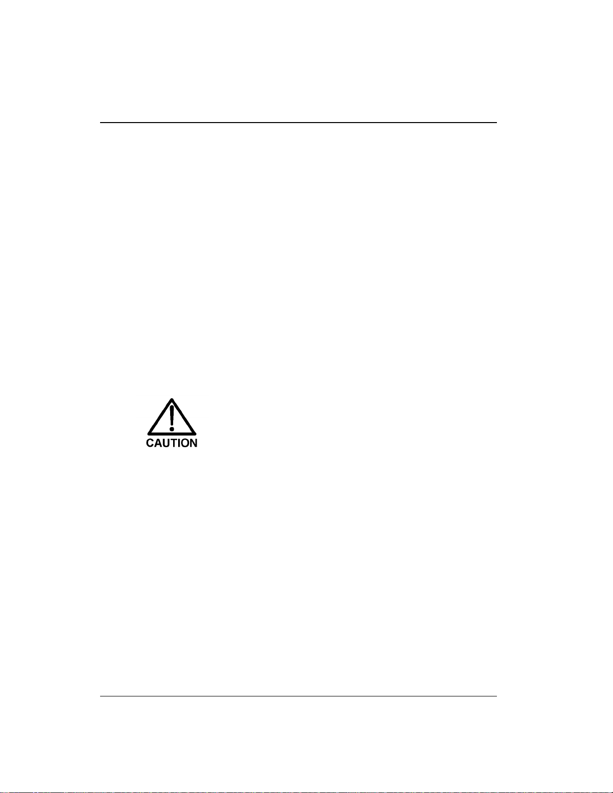
The interior of the LC20 is a n insulated, passive chamber. It
contains a slide-out panel for mounting components. Figure 2-1
illustrates the LC20 chassis. See Section B.2. 1 for recommended
stacking configurations. See Figure 2-2 for an illustration of the
slide-out component pa nel.
2-4
Figure 2-1. LC20 Interior Chassis
Doc. 034 859-02 9/93
Page 15
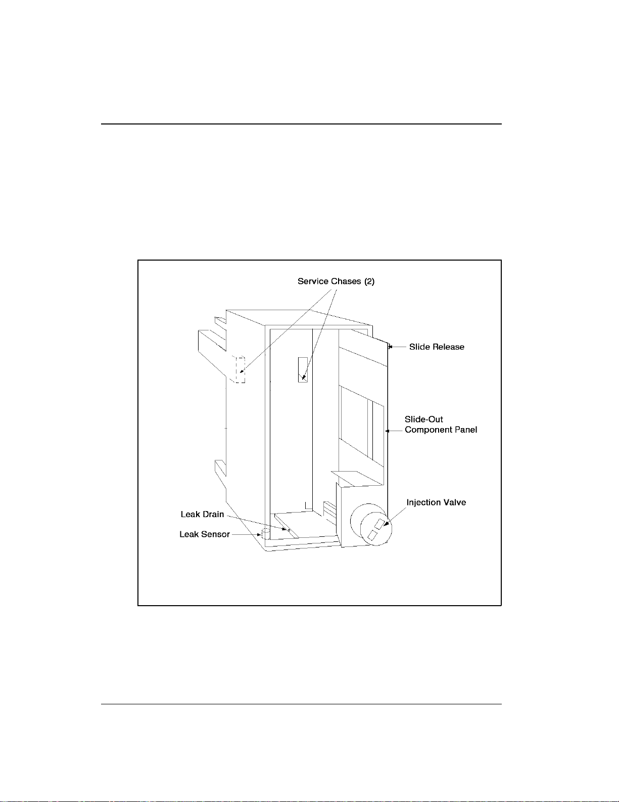
2.3. 1 Component Panel
Components are mounted o n the slide-out panel. The panel
on the right side is standard in all LC20 enclos ures. When a
dual-channel modu le is ordered, an o pposite panel is
factory-installed on the left side (see Figure 2- 2).
2 • Description
Doc. 034859 -0 2 9/93
Figure 2-2. Component Panel Layout
2-5
Page 16

LC20 Chromatography Enclosure
The component pa nel has two slide releases to lock it in a
fully closed (in) or op en (out) posi tion. Press th e slide rele ase
at the upper horizontal edge of the panel to release the detent.
The panel will lock at about three q uarters of its total travel
when you pull it out. This prevents it from being pulled
entirely out of the tracks and possibly damaging the
components. To reinsert the panel, press th e second slide
release and push it back into its closed position. The fully
closed position locks the panel and prevents it from being
forced outward by pressure from the vario us tubing
arrangements.
The panel can b e pulled completely out by pressing the
second slide release a nd pulling the panel until it clears the
top and bottom tracks. H old the panel securely when it
disengages the tracks. To replace the panel, align it with the
top and bottom tracks and push inward until it engages the
second detent. Pre ss the second slide release a nd push the
panel to its closed and locked position.
2-6
Various component arrang ements are made pos sible by
multiple mounting ho les and slots. The configuration s hown
here is only on e of many offered by the enclos ure.
2.3.2 Rheodyne Injection Valve
The Rheodyne injection valve is mounted at the bottom of the
component pane l. Its control knob exten ds through the door
to allow manual operation with the doo r closed. The valve
has two operating positions:
The injection valve is a low-volume, metal-free, 35 MPa
(5000 psi) rotary injec tion valve. It accommodates syr inge
injections or pressurized sample loading.
The Rheodyne injection valve is equippe d with a microswitch
for detection of the valve position. The microswitch can be
wired to a module that can p rocess the signal to verify the
position of the valve.
INJECT
and
LOAD
.
Doc. 034 859-02 9/93
Page 17

The LC20 S hip Kit in cludes two acce ssories fo r the
Rheodyne injection valves: a 25 µL gas-t ight syrin ge
(P/N 041389) and a 25 µL sample loop (P/N 0 42857). For
more information about the valve, including important
operating precautions, refer to the
Manual
(Document No . 034468), inclu ded in the LC20 Ship
Kit.
2.3. 3 Self-Regenerating Suppressor
The Self-Regenerating Suppresso r (SRS) is held in place
by a special support pla te. Align the two slots on the botto m
of the SRS case with the tabs on the suppo rt plate. Press
and then
down
to lock the SRS in place. Pull up and then
to remove (see Figure B-8 in Appendix B).
2.3.4 Leak Sensor
This sensor detects leaks and spills in th e bottom of the
enclosure, a nd generates a signal wh en a leak occurs . The
sensor is located at the lower front corner of the left wall in
the bottom tray. Its cable exits through the rear service ch ase,
and must be conne cted to the GP40 pump .
2 • Description
Rheodyne Valve Operator’s
in
out
2.3. 5 Separator Columns
2.3.6 Guard Columns
Doc. 034859 -0 2 9/93
The column mount n ear the front of th e component panel c an
accommodate up to two separato r columns. The colu mn
mount supports 4-mm columns on one side and 2-mm
columns on the other. The column mount can be removed by
pressing on each side of its mounting ta b and pulling away
from the slot in the panel. Yo u can then reverse it and press it
back into the panel to ch ange column size and maintain the
columns at the outer positio n (see Figure B-7 in Appendix B).
The smaller gu ard columns (if used) are held in pl ace by the
tubing below the separator columns.
2-7
Page 18

LC20 Chromatography Enclosure
2.3.7 Col umn Select Valve
The column selec t valve (P/N 044858), when included, will
be supported o n the component pan el by a mounting plate .
The column select valve is controlled by the pump through a
pair of air solenoids on the back of the LC20.
The column select valve is not normally plumbe d into the
system. However, enough tubing is provided in the LC20
Ship Kit to plumb u p to two column select valves into two
systems. When plumb ed, the optional 28 MKa (400 0 psi)
column sel ect valve directs the flow of eluent a nd sample
from the Rheodyne injection valve to either column A or B.
The column select valve can alternatively be used to switch in
and out a separator c olumn.
The column select valve is actuated by a pair o f solenoids
mounted on the rear panel, which will be included only wh en
the column select valve is installed. The solenoids are
electrically co nnected to and controlled b y the GP40 or IP20
pump. Refer to the pump manual for operating instructions.
2-8
Figure 2-3 shows the assembly of the column select valve.
Doc. 034 859-02 9/93
Page 19
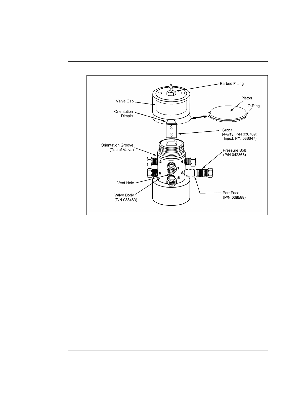
2 • Description
Doc. 034859 -0 2 9/93
Figure 2-3. Column Select Valve
The groove around the valve body in dicates the top of the
valve. The ports are numbe red clockwise aroun d the valve
body. The small vent hole is between ports 1 a nd 5. Pressure
bolts provide an intermediate conn ection between the valve
slider and all tube fittings.
These bolts must be tightened
evenly to provide uniform sealing pressure against the
valve slider and ensure leak-free operation.
maintenance information, refer to the
Installation and
Maintenance of the Dionex High Pressure Valve
. For valve
(Document
No. 032678).
2-9
Page 20
LC20 Chromatography Enclosure
The valve is operated by a ir pressure push ing against pistons
inside the valve cap. The p iston pushes a slider up and down
inside the valve body. Applying pressure to the top piston
pushes the slider down; applying pressure to the bottom
piston pu shes the sl ider up. T he slider con nects the valve
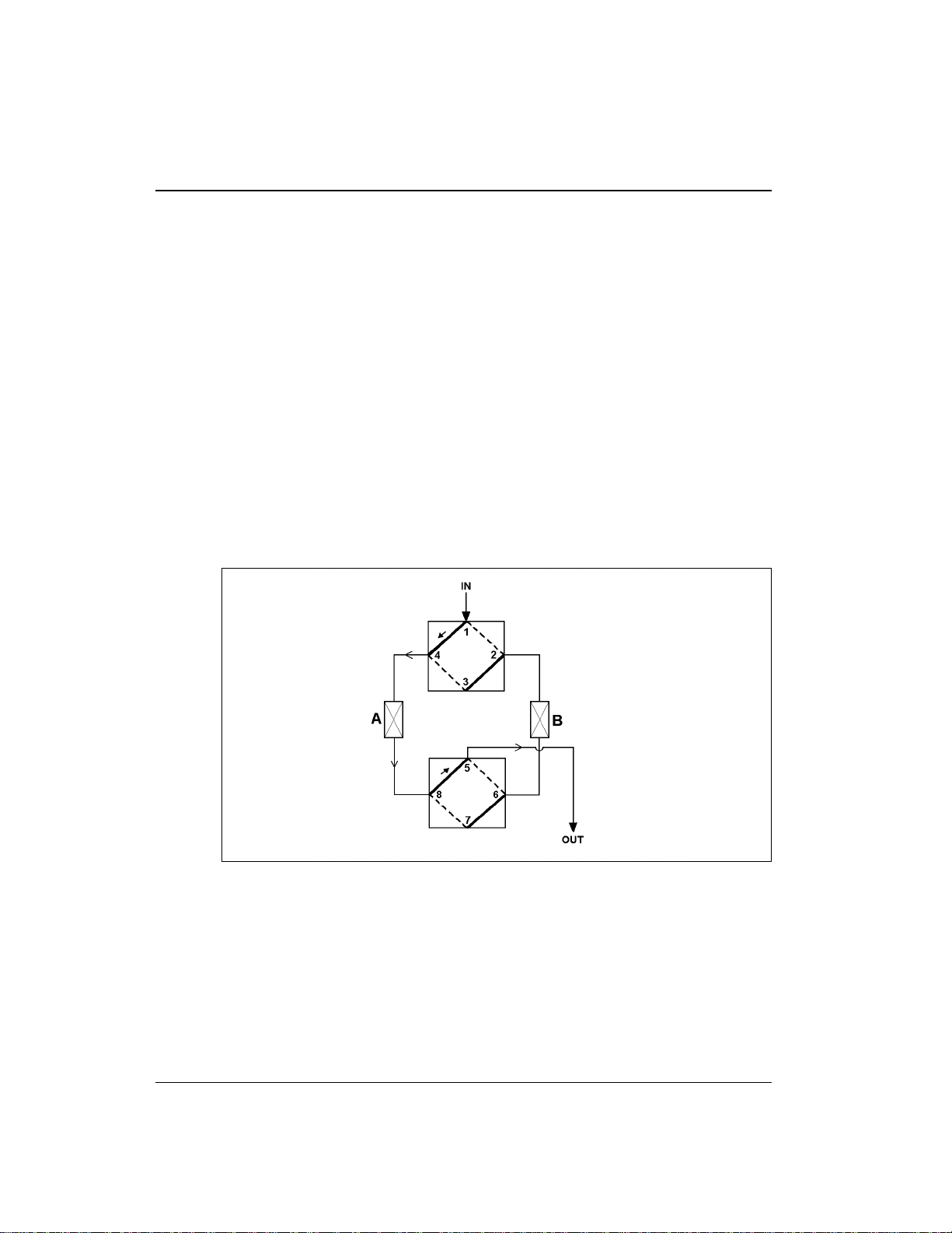
ports as follows (see Figure 2-4 ).:
Switch in OFF position, selecting column A (slider down):
1 → 4 and 2 → 3,
5 → 8 and 6 → 7
Switch in ON position, s electing column B (slider up):
1 → 2 and 3 → 4,
5 → 6 and 7 → 8
2-10
Figure 2-4. Column Select Valve Slider Connections
The valve is tested to op erate leak-free at 28 M Pa (4000 psi).
After testing, the valve pressure bolts are loosened to reduce
stress on critical parts during storage. Before shipment, the
pressure b olts are tigh tened to provide leak-free oper ation at
pressures up to 17 MPa (2500 psi) or 90 in-oz torque. If yo u
Doc. 034 859-02 9/93
Page 21

need to o perate at hig her pressu res (up to 2 8 MPa, or
4000 psi), first torque the bolts to 128 in-oz . If the valve is to
be unused for mo re than two days, red uce the torque o n the
bolts to 90 in-oz while ins talling or removing the fittings.
Use a wrench on the valve pressure bolt to prevent it from
turning while loosening the fitting. Refer to
Maintenance of the Dionex High-Pressure Valve
No. 032678) for additional information.
2.3.8 Detector Cells
Detector cells for the CD20 Conductivity Detector or the
ED40 Electrochemical De tector are mounted o n the
component pane l. Their cables exit thr ough one of the serv ice
chases on the r ear panel.
2.3. 9 DS3 Detection Stabilizer (Optional)
The DS3 improves baseline stability by da mping fluctuations
in temperature, thus improving detection at trace levels. Refer
to the
DS3 Detection Stabilizer Installation Instructions
(Document No. 0348 50).
2 • Description
Installation and
(Document
Doc. 034859 -0 2 9/93
2-11
Page 22

LC20 Chromatography Enclosure
2.4 Rear Panel
The rear panel provides installation space for air and valve
connectors (see Figure 2-5).
2-12
Figure 2-5. LC20 Rear Panel
Doc. 034 859-02 9/93
Page 23

2.4.1 Cell Cables
The cables ins ide the LC20 , which connec t the detector cel l
to the CD20 Cond uctivity Detector or the ED40
Electrochemical Detector normally exit through service chase
in the rear panel ( see Figure 2-5).
2.4 .2 Waste Line
The cell and suppressor waste lines from insid e the LC20
normally exit through the service chase in th e rear panel (see
Figure 2-5). The injection valve waste lines should exit
through the lower side s lots of the enclosure .
2.4.3 Solenoid Interface
The air-actuated solenoid valves used to control the inje ction
valve and the column select valves (if installed) are
controlled directly by the pump. The solenoids are installed
as pairs; one pair is shown in Figure 2-5.
2 • Description
Doc. 034859 -0 2 9/93
Refer to the GP40 Gradient Pump or IP20 Isocratic Pump
manual for connection details.
2-13
Page 24

LC20 Chromatography Enclosure
2-14
Doc. 034 859-02 9/93
Page 25

3 • Operation and Maintenance
3.1 Routine Operation . . . . . . . . . . . . . . . . . . 3-3
3.1.1 Sample Loading . . . . . . . . . . . . . . 3-4
3.2 Shutdown . . . . . . . . . . . . . . . . . . . . . . 3-7
3.3 Routine Maintenance . . . . . . . . . . . . . . . . 3-7
Doc. 034859 -0 2 9/93
3-1
Page 26

LC20 Chromatography Enclosure
3-2
Doc. 034 859-02 9/93
Page 27

3 • Operation and Maintenance
3.1 Routine Operatio n
Inside the Rheodyn e injection valve, eluent flows through one of
two paths depending on the position of the injection valve knob (see
Figure 3-6).
Figure 3-6. Injection Valve Schematic
In th e
column without en tering the sample loop. Sample flows from the
syringe into the valve and through the sa mple loop, and excess
sample flows out to waste.
In th e
sample loop, and out to the column (carrying the contents of the
sample loop with it).
Doc. 034859 -0 2 9/93
position, eluent flows in from the pump and out to the
LOAD
INJECT
position, eluent flows in from the pump, thro ugh the
3-3
Page 28

LC20 Chromatography Enclosure
3.1. 1 Sample Loading
The Rheodyne injection valve may be filled completely or
partially. These techniques differ in accuracy, precision, and
the amount of sample r equired. Refer to th e Rheodyne valve
Operating Instructions
selecting a method for your application.
Before filling the injection valve sample loop, set the
Rheodyne injection valve knob to
There are fo ur methods for plumbin g the Rheodyne valve
sample loop:
When inserting needles into the needle port, use only
0.028-inch OD (22 gauge) x 2-in. long needles with 90
degree point style (square end). Using the incorrect needle
size can damage the injector.
Direct injection into the valve:
1.
LOAD
its
position. Insert the syringe into the needle port
on the injection valve (see Figure 3-6). Overfill the
sample loop with several sample loop volumes. Excess
sample will flow out thro ugh the waste line. L eave the
syringe in th e needle port until the injection valve knob is
turned to
INJECT
.
included in the LC20 Ship Kit before
LOAD
(see Figure 3-6)
Set the injection valve to
3-4
Drawing sample through the waste line:. Place the
2.
injection valve into its
LOAD
position. Insert the syringe
into the need le port on the Rheo dyne valve, place the
valve waste line (port #6) into the sample container (see
Figure 3-7). Draw sample into the loop throu gh the
injection valve waste line. No sample will c ome into
contact with the metal ne edle of the loading syringe.
Remove the sample from the sample container. Leave the
syringe in the needle port until the injection valve knob
has been switched to
INJECT
.
Doc. 034 859-02 9/93
Page 29

3 • Operation and Maintenance
Figure 3-7. Drawing Sample
Doc. 034859 -0 2 9/93
3-5
Page 30

LC20 Chromatography Enclosure
Loading sample through the waste line:
3.
possible outgassin g effects of using suction to draw the
sample through the waste line, connect a luer fitting and
sample-filled syringe in the end of the waste line. Connect
the other end of the waste line into injection valve port
#6. Place the valve in its
adaptor shipped with the Rheodyne valve into the needle
port. Push sa mple through the waste line. Waste will exit
the valve through the n eedle adaptor. No sample to be
analyzed will come into contact with the metal needle of
the needle adaptor (see F igure 3-8).
To avoid the
LOAD
position. Insert the needle
3-6
Figure 3-8. Loadng Sample
Loading from an automate d sampler:
4.
See the
autosampler operator’s manual for instructions.
Doc. 034 859-02 9/93
Page 31

3.2 Shutdown
If the LC20 will not be us ed for more than three days and if the
column select valve is torqued for high pressure, reduce the torqu e
on the pressure bolts to 90 in-oz to prevent possible damage to the
valve .
If other modules are connected to the rear panel power s trip, make
sure the fr ont panel doo r is fully clos ed. Press the power actuator
switch on the fron t panel to shut off power to other modu les. The
power actuator rod leading the power switch at the rear of the
module will not op erate if the door is open.
3.3 Routine Maintenance
•
Periodically check for leaks or spills inside th e LC20. Locate and
repair leaks and clean up spills. Rinse all dried eluents
(especially when they include salt solutions) o r reagents off
system compone nts with deionized wate r or, in the case of
spilled ninhydrin, with isopropyl alcohol.
3 • Operation and Maintenance
•
Periodically check all air and liquid lin es for crimping. Move or
reroute pin ched lines; replace d amaged lines.
Doc. 034859 -0 2 9/93
3-7
Page 32

LC20 Chromatography Enclosure
3-8
Doc. 034 859-02 9/93
Page 33

4 • Troubleshooting
4.1 Liquid Lea ks . . . . . . . . . . . . . . . . . . . . . 4- 3
4.2 Excessive System Backpressure . . . . . . . . . . 4-4
4.3 Inopera tive Column Sele ct Valve . . . . . . . . . 4-5
4.4 Column Select Valve Air Leaks . . . . . . . . . . 4-5
4.5 Peak Ghosting . . . . . . . . . . . . . . . . . . . . 4-6
4.6 Non-Repr oducible Peak Heig ht or Retention
Tim e . . . . . . . . . . . . . . . . . . . . . . . . . 4-6
4.7 Abnormal Retention Time or Selectivity . . . . . 4-6
Doc. 034859 -0 2 9/93
4-1
Page 34

LC20 Chromatography Enclosure
4-2
Doc. 034859- 02 9/93
Page 35

4 • Troubleshooting
Use this troubleshooting guide to isolate and solve problems that
may occur while using the LC20. If the re is more than one possible
cause, read the potential sources of the prob lem to determine which
may be the most applicable. If th e problem persists, call the nearest
Dionex Regional Office.
For troubleshooting pr ocedures specific to the Rheodyne injection
valve, re fer to the Rheodyne Valve Operator’s Manual (Document
No. 034468).
4.1 Liquid Leaks
•
Leak ing fitt ing.
Locate the source of the leak. Make sure all liqu id line
connections are tight:
1. If the con nections are made with Dionex ferrule fittings,
see Installation o f Dionex Ferrule Fittings (Document
No. 034213) f or instructions.
•
Broken liquid line.
•
Blocked or improperly installed waste line.
Doc. 034859 -0 2 9/93
2. If the colu mn select valve is plumbed into the system,
remove the valve from its mounting clip to improve
access t o all valve ports. Use a wrench on the valve
pressure bolt to prevent it from turning while tighte ning
the fitting.
Replace the f errule or r eplace the tubin g.
Make sure th e waste lines from the valves and ce lls are not
crimped or otherwis e blocked. Also make sure they are not
elevated at any point after they exit the modu le.
4-3
Page 36

LC20 Chromatography Enclosure
• Pressure bolt(s) on c olumn switching valve are too loose.
Follow the procedure below to tighten the pressure bolts:
1. Turn off the liquid flow.
2. Tighten each pressure bolt fingertight, the n use an
open-end wren ch to tighten an additional one-eighth tu rn.
NOTE
All eight pressure bolts must be evenly tightened
against the slider for optimum leak-free operation.
3. Turn on the liquid flow evenly and check for leak s.
Tighten pressure bolts further if leaks appear.
NOTE
Use a torque wren ch to evenly tight en pressure bolts
for optimum l eak-free operati on. Refer to
and Mainte nance of the Dionex Ine r t H ig h P ressu re Valve
(Document No. 032678) for torque requirements.
Installation
• A co lumn select valve port is scra tched.
Replace t he port face.
4.2 Excessive System Backpressure
• Restriction in the hydraulic system.
1. Chec k all liquid lines and valves for crimping or
blockage. Make sure ferrule fittings are not overtightened
into Tefzel tubing. Refer to
Fittings
(Document No. 034 213) for details.
2. Verify that valves are being fully activated (not between
positions).
• Flow rate through the columns is too high.
Reduce the flow rate.
4-4
Installation of Dionex Ferrule
Doc. 034859- 02 9/93
Page 37

• Clogged co lumn bed supports.
Replace th e bed support s as instructe d in the col umn manual.
• Columns are contaminated.
Clean the columns (see Column Rejuvena tion Procedures,
Technical Note 2 R, Document No. 032036).
4.3 Inoperative Column Select Valve
• Air is not reaching t he valve.
Check that the air s upply is turned on a nd is supplying 550 to
820 KPa (80 to 120 psi).
• Air tubing harness is crimped or blocked.
Check the air tu bing for blockage. R emove and replace any
blocked tubing. Re position crimped or pinch ed tubes.
• Air le ak.
4 • Troubleshooting
Air leaks are usually audible; isolate and eliminate leaks.
• Valve is incorrectly plumbed.
Check that the system is correctly plumbed . Re-plumb the
system if n ecessary.
• Pressu re bolts on th e column sele ct valve are too tig ht.
Follow the procedure in Section 4.1 to loosen the pressure
bolts if the column select valve is plumbed into the system:
4.4 Column Select Valve Air Leaks
• Air le ak.
Air leaks are us ually audible and f requently cause excessive
cylinder gas/air consu mption. Locate and rep air the leak.
Doc. 034859 -0 2 9/93
4-5
Page 38

LC20 Chromatography Enclosure
4.5 Peak Ghosting
Ghosting is the appear ance of extraneous peaks in a
chromatogram. These may be late-eluting peaks from a previous
injection or result from a contaminated valve or a poor sample
loading technique. These peaks may co-elute with peaks of
interest, resulting in non-reproducible peak heights.
• Insufficient time between sample injections.
Wait until the previous sample has been completely eluted
before making anoth er injection.
• Insufficient flush between samples.
Flush the sample loop with at least 10 loop volumes of
deionized water or sample between sample injec tions.
4.6 Non-Reproducible Peak Height or Retention Time
• Column overloa ding.
1. Chan ge to a sample loop with a sm aller volume.
2. Dilute th e sample.
• Liquid leaks.
Locate and eliminate the leaks.
Also see “Peak ghosting” in Section 4.5 above.
4.7 Abnormal Retention Time or Selectivity
• System is not equilibrated following an eluent change .
Allow the system to equilibrate with at least 2 0 column
volumes of eluent (for example, 30 minutes at 2. 0 mL/min
for 4 mm anion separator columns).
• Flow rate through s ystem is inco rrect.
1. Ch eck that the correct flow ra te is selected .
4-6
Doc. 034859- 02 9/93
Page 39

2. Loc ate and eliminate any liquid leaks.
• Cont aminated or in correct eluent.
Remake the elu ent using reagent grad e chemicals an d ASTM
filtered Ty pe I (18 megohms or 1 µS) grade deion ized water.
• Contaminat ed or degraded sample.
Take appropriate precautions when preparing and storing
samples to prevent contamination and degradation.
• Column is contaminated.
1. Cl ean the column (see Col umn Rejuvenation Procedures,
Technical Note 2R , Document No. 03 2036).
2. If cle aning is unsuccess ful, replace the column .
4 • Troubleshooting
Doc. 034859 -0 2 9/93
4-7
Page 40

LC20 Chromatography Enclosure
4-8
Doc. 034859- 02 9/93
Page 41

5 • Service
5.1 Introduc tion . . . . . . . . . . . . . . . . . . . . . 5-3
5.2 Tube Fitting Installation . . . . . . . . . . . . . . 5-3
5.3 Restriction in the Hydraulic System . . . . . . . . 5-4
5.4 Injectio n or Column Select Va lve Liquid Leaks . 5-4
5.5 Column Select Valve Air Leaks . . . . . . . . . . 5-5
5.6 Cleaning the Column Select Valve Slider . . . . . 5-6
5.7 Rep lacing the Col umn Select Valve Port Face . . 5-9
5.8 Servicing the Rheodyne Injection Valve . . . . . 5-9
Doc. 034859 -0 2 9/93
5-1
Page 42

LC20 Chromatography Enclosure
5-2
Doc. 034859- 02 9/93
Page 43

5 • Service
5.1 Introduction
This section describes service and repair procedures for the LC20.
These services are required rarely, but some wear of the fittings and
tubing is to be expecte d during the life of th e enclosure. Be fore
repairing or replac ing any part, refer to Chap ter 4 to isolate th e
source of the prob lem. For service and maintenance procedures for
the Rheodyne injec tion valve, refer to the Rhe odyne manual
supplied in the LC20 Ship Kit.
When ordering replacement parts, pleas e include the mo del and
serial number of you r LC20. If poss ible, also provide the par t
numbers and, whe re applicable, the revision number of the items
you are ordering.
5.2 Tube Fitting Installation
The LC20 is plumbed with Dio nex 10-32 ferrule fittings. PEEK
tubing is recommended for use throughout the system. However,
ThermoFlare tu bing may b e installed whe re pressures are below
7 MPa (1000 psi); this includes waste line s, tubing from an
autosampler to the Rheody ne valve injection port, or tubing from the
separator column to the suppressor. Use 1.6-mm (0.063-in) ID
Teflon tubing for regenerant lines for both the 2-mm and 4-mm
suppr e ss o rs.
For instructions on how to install ferrule fittings on PEEK or Tefzel
tubin g, refe r to Installation of Dionex Ferrule Fittings (Document
No. 034213), p rovided in the LC20 Sh ip Kit.
Doc. 034859 -0 2 9/93
5-3
Page 44

LC20 Chromatography Enclosure
5.3 Restriction in the Hydraulic System
A restriction in the hydraulic system will cause excessive system
backpressure.
1. Begin pump ing eluent through the system (including the
columns) at the flow rate normally used.
2. Follow the appropriate hydraulic schematic (see Figures B-4
through B-6) and work backward th rough the system, beginnin g
at the cell exit. One at a time, loo sen each fitting and observe the
pressure. Th e connection at whic h the pressure drops indic ates
the point of po int of restriction.
3. Remove the res triction either by bac k flushing or by replacing
the section of tubin g.
4. If the restriction is caused by the column select valve,
disassemble t he valve and clean th e slider (see S ection Figur e
2-4. Column Select Valve Slider Connections
5.4 Injection or Column Select Valve Liquid Leaks
A poor seal be tween the fe rrule sealin g surface and t he valve
pressure bolt or b etween the po rt face an d the valve slider may
cause the co lumn select valve t o leak (see F igure 2-3). The flow
rate through the system may be low, producing chromatograms
with longer than normal retention times and poor reproducibility.
1. Tighten any loose fittings fingertight, then an additional
one-eighth turn. Tighten further only if a leak co ntinues.
DO NOT OVERTIGHTEN. Use an open end wrenc h to hold
the valve pressure bolts to prevent them from turning
when tightening connections to the valves.
5-4
Doc. 034859- 02 9/93
Page 45

5 • Service
2. If tightening the fitting does not stop the leak, disconnect the
fitting from the valve. Occasionally, fittings stop leaking if
simply disconnected and th en immediately reconnected. If the
leak continues, install a sh ort length of tubing, with fittings,
between the pressure bolt and the suspect fitting. Connect the
fitting to the tubing with a union. A leaking fitting will also leak
inside the union. If necessary, replace the fitting.
If you replace
the fitting , also replace t he ferrule.
NOTE
When connecting or disconnecting fittings from the valve
pressure bolts, use a wrench to hold the bolt and prevent it from
turning.
3. Make sure all valve pressure bolts are evenly tightened. Refer to
Installation and Mainten ance of the Dionex Inert High-Pressure
Valve
(Document No. 032678) for the torqu e requirements.
Use caution as overtightening may break off the bolt in the
valve body.
4. If tighte ning the pressure bo lts does not stop the leak, refer to
Section 5.7 for instructions to replace the port face.
5.5 Column Select Valve Air Leaks
An air leak around the valve piston or cap results in excessive
air consumption and may cause the valve to operate sluggishly
or not at all.
1. Remove the column switch ing valve from its mounting clip.
2. Make s ure that the top and b ottom caps are tight. If necessary,
tighten them fingertight.
3. If the leak contin ues, determine which end of th e valve leaks by
activating the corresponding switch. Air will escape through the
vent hole wh en the leaking end is press urized.
4. Dis connect the a ir line from th e leaking cap. I f necessary, use
the valve switch to turn off the air th rough the disco nnected line.
Doc. 034859 -0 2 9/93
5-5
Page 46

LC20 Chromatography Enclosure
5. Un screw the leaking cap from the valve body (Figure 2-3) .
Inspect the cap O-ring for crack s and replace if necessar y
(P/N 038650) .
6. Pres s the discon nected air lin e (Step 4) again st the small vent
hole between ports 1 and 5. Ac tivate the valve switch to apply
air pressure against the slider. The piston will pop out of the
valve body.
7. Ins pect the pi ston O-ring for cracks and r eplace if neces sary
(P/N 038651) .
8. Carefully lubricate the p iston O-ring with a small amount of
silicone grease.
Use the grease sparingly . Excess grease may co ntaminate
the eluent.
9. Press th e piston back into the valve body.
10. Make s ure that the cap O- ring is inside the c ap. Screw the cap
back onto the valve body. Tighten it only fingertight.
11. Reconnec t the air line to the valve.
5.6 Cleaning the Column Select Valve Slider
A dirty or plugged valve slider cau ses excessive system
backpressure and may cause poor chromatographic
performance.
1. Turn off the pump and th e eluent selector valves.
2. Remove the plu gged valve from its mounting clip (se e Figure 2-3
3. Dis connect the a ir line from o ne cap. If necessary, use the valve
switch to turn off the air through the d isconnected line.
5-6
Doc. 034859- 02 9/93
Page 47

5 • Service
4. Un screw one cap from the valve body. Be careful not to lose the
cap O-ring.
5. Pres s the discon nected air lin e (Step 3) again st the small vent
hole between ports 1 and 5. Ac tivate the valve switch to apply
air pressure against the slider. The piston will pop out of the
valve body.
6. Turn off the ai r sup ply.
7. Carefully loosen ea ch of the pressure bolts one-eighth turn to
disengage the po rt faces from the slider. Do not loose n any
further.
8. Rem ove the other cap . Push on t he slider to force the oth er
piston out of the valve body.
9. Carefully p ush the slider out o f the valve body with a blu nt rod.
10. Ins pect the slider surfa ce. If there are scratches i n the sur face,
replace the s lider (P/N 038709) .
11. Pla ce the slider in a small co ntainer of deio nized water or
methanol. Sonicate or agitate vigorou sly for several minutes.
12. Rins e the slider with deionized water. Blow any water out of the
holes and inspect them f or blockage. Use a fine piece of wire
(0.025 in) to dislodge any remaining b lockage. Be carefu l not to
scratch the slider surface. If the blockage cannot be removed,
replace the sli der.
13. Push the slider back into the valve body. Orient the dimple on
the top of the slider between por ts 1 and 2 of the valve body (see
Figure 2-3).
The valve operates properly on ly if the sli der is corr ectly
oriented in the valve body. The groove around the valve body
indicates the top of the valve body. The small vent hole is
between ports 1 and 5. The ports a re numbered clockwise fro m
the top around th e valve body. The slider co nnects the ports as
follows:
Doc. 034859 -0 2 9/93
5-7
Page 48

LC20 Chromatography Enclosure
Switch in OFF or LOAD position (slider d own):
1 → 4 and 2 → 3
5 → 8 and 6 → 7
Switch in ON or INJECT pos ition (slider up):
1 → 2 and 3 → 4
5 → 6 and 7 → 8
14. Ins pect the piston O-ri ngs (P/N 038651) and replace them if
necessa ry.
15. Carefully lubricate the pisto n O-rings with a small a mount of
silicone grease and reassemble the valve (see Section 5.5 for
instructions to correct Column Select Valve air leaks).
16. Tighten each pressure bolt fingertight, the n use an open e nd
wrench to tighten a n additional one-eighth turn.
For optimal leak-free operation a t 28 MPa (4000 psi), a ll eight
pressure bolts must be evenly tightened against the slider
(128 in-oz). A spec ial torque wrench kit (P/N 03894 3) is
available from Dionex.
17. Turn on the liquid flow and check for lea ks. Tighten the pressure
bolts further if leaks appear.
Use cauti on as overtighteni ng may
break off the bolt in the valve body.
18. If cleaning the valve slider does not eliminate the backpressure
problem, see the next section for instruction s to replace the port
face.
5.7 Replacing the Column Select Valve Port Face
A scratched port face may cause a leak around the pressure bolt.
A plugged port face will cause excessive system backpressure
and may cause poor chromatographic performance.
1. Turn off the liquid flow.
2. Remove the valve from its mounting clip.
5-8
Doc. 034859- 02 9/93
Page 49

5 • Service
3. Disconnect the tube fitting from the pressure bolt that shows
evidence of leaking, then unscrew the pressure bolt from the
valve body.
4. Inspect the port face. If it is scratched or plugged, c arefully pry
it out of the pres sure bolt, using the extractor tool (P/N 038930)
designed for th is. Press a new port face (P/N 038599) into the
pressure bolt.
Be careful to not scratch the sealing surfaces!
5. Screw the pressure bolt into the valve body. Tighten each
pressure bol t fingertight, th en use an o pen end wrench to tighten
an additional one-eighth turn.
For optimal leak-free operation a t 28 MPa (4000 psi), a ll eight
pressure bolts must be evenly tightened against the slider
(128 in-oz). A spec ial torque wrench kit (P/N 03894 3) is
available from Dionex.
6. Turn on the liq uid flow and check for leaks . Tighten pressure
bolts further if leaks appear.
For optimal leak-free operation, a torque wrench can be used to
evenly tighten pressure bolts. Refer to
Installation and
Maintenance of the Dionex Inert High-Pressure Valve
No. 032678) for torque requirements.
Use caution as
overtightening may break off the bolt in the valve body.
7. Reconnect the tube fitting to the pressure bolt. Use a wren ch to
prevent the pressure bolt from turning while tightening the
fitting. Tighten the fitting fingertight, then an additional
one-eighth tur n. Tighten further only if leak s appear.
5.8 Servicing the Rheodyne Injection Valve
The Rheodyne injection valve requires infrequent servicing. See the
Rheodyne Valve Operator’s Manual
specific maintenance and service requirements. For major
disassembly, contact th e nearest Di onex Regional Office for
assistan ce.
Doc. 034859 -0 2 9/93
(Document No. 0 34468) for
(Document
5-9
Page 50

LC20 Chromatography Enclosure
5-10
Doc. 034859- 02 9/93
Page 51

A • Specifications
A.1 Environmental . . . . . . . . . . . . . . . . . . . . A-3
A.2 Physical . . . . . . . . . . . . . . . . . . . . . . . A-3
A.3 Hydraulics . . . . . . . . . . . . . . . . . . . . . . A-3
A.4 Insulation . . . . . . . . . . . . . . . . . . . . . . A-4
Doc. 034859 -0 2 9/93
A-1
Page 52

LC20 Chromatography Enclosure
A-2
Doc. 034 859-02 9/93
Page 53

A.1Environmental
A • Specifications
Ambient
Temperature:
Humidity: 5-95% relative (non-condensing)
Air Pressure: 400 to 800 KPa (60 to 120) psi for the Rheodyne injection
Operating
Pressure:
A.2Physical
Dimensions: 50 cm high x 22.5 cm wide x 49 cm deep
Weight: 12 kg (25 lbs)
A.3Hydraulics
4 °C to 75 °C
(40 °F to 167 °F)
valve and column select valve;
Use laboratory-quality air or regulated compressed air,
nitrogen, or helium.
35 MPa (5000 psi) maximum liquid path (tubing, valves,
columns, etc.)
(20.8 in x 8.9 in x 20.4 in)
6 cm clearance required in back of the module
Rheodyne
Injection Valve:
Column Select
Valve:
Doc. 034859-02 9/93
35 MPa (5000 psi) metal-free or stainless steel rotary valve
for low-volume injections.
28 MPa (4000 psi) metal-free column select valve to direct
eluent and sample to one of two columns. The column select
valve option is installed at the factory but i s not plumbed into
the system. Tubing to plumb the LC20 for column select
applications is included in the LC20 Ship Kit (P/N 046300).
A-3
Page 54

LC20 Chromatography Enclosure
A.4 Insulation
Dampening Dampens o utsi de temper ature vari ations by a fa ctor of
–5 to 10 over 10 minutes
–2 to 4 ove r 60 m in utes
A-4
Doc. 034 859-02 9/93
Page 55

B • Installation
B.1 Facilities Required . . . . . . . . . . . . . . . . . B-3
B. 2 Inst allation Ins tr uctions . . . . . . . . . . . . . . . B-4
B. 2. 1 Stac king Modules . . . . . . . . . . . . . B-4
B. 2. 2 Waste Lines . . . . . . . . . . . . . . . . . B-5
B.2.3 Leak Control . . . . . . . . . . . . . . . . B-6
B.2.4 Liquid Line C onne ctions . . . . . . . . . B-6
Injection Valve Connections . . . . . . B-7
B. 2. 5 Detector C ells . . . . . . . . . . . . . . . B-9
External Cell . . . . . . . . . . . . . . . B-9
Inte rn al Ce ll . . . . . . . . . . . . . . . B- 10
B.2.6 Column Installation . . . . . . . . . . . . B-12
B.2.7 SRS Installation (Optional) . . . . . . . . B-13
B.2.8 Solenoid Valve Connections to the
Pump . . . . . . . . . . . . . . . . . . . . B-14
Doc. 034859 -0 2 9/93
B-1
Page 56

LC20 Chromatography Enclosure
B-2
Doc. 034859- 02 9/93
Page 57

B • Installation
B.1 Facilities Required
Appendix A of this manual co ntains the complete LC20
specifications. The location selected to install the L C20 should also
meet the following requirements:
•
A sturdy table o r work bench with at least 15 cm (6 in) free
space behind the mo dule for connections and ventila tion.
Maximum horizontal slope is 2-cm pe r lateral meter (0.25-inch
per lateral foot).
•
Nitrogen, argon, or helium gas cylinder for reservoir pressure.
•
As the enclosure d oes not have temperature c ontrol, the
environment will affect the enclosure operation. The system
should be installed with adequate ventilation and in an
environment that provides maximum consistency in ambient
temperature and humidity. In general, y ou should
— avoid sun and proximity to hot equipment.
— avoid heavy air drafts and sudden temperatu re changes
— not operate the enclosure in conden sing atmospheres
— maintain s pecified ambient temperatures.
Connect gas/air pressure to the solenoids on the rear pan el (see
Figure 2-5). The gas/air pressure is route d to the enclosure valves
through air valves, which are actuated electrically by the pump.
Connect th e wiring to the proper co nnector on th e pump accordi ng
to the plumbing schematics further in this chapter.
Doc. 034859 -0 2 9/93
To avoid contamination and possi ble deter ioration of the
valves, make sure laboratory pneumatic air, if used, is
oil-free, dry, and filtered, and maintained within the
pressure limits specified above.
B-3
Page 58

LC20 Chromatography Enclosure
B.2 Installation Instructions
A Dionex-trained representative will install the LC20 and other
system modules for yo u. The instructio ns given here are for your
reference. Conta ct the nearest Dionex Regional O ffice for assistance
if you experience any difficulties durin g or after installation that a re
not addressed in this manual.
B. 2. 1 Sta cking Mo dules
Dionex DX-500 Chroma tography Syst em modules are d esigned
to be stacked on top of each ot her up to a maximu m height of
four units. The e nclosure is three units high and should not be
stacked on any other unit. The enclosu re should not have more
than one single- unit module on to p of it, such as a CD20
Conductivity Detector, ED40 Electrochemic al Detector, or the
EO1 Eluent Organizer (P /N 044125). Fig ure B-1 illustrates the
recommended stacking configuration.
B-4
Figure B-1. Recommended Stacking Configuration
Lift the module only from the bottom surface. Do not lift
it with the panel doors as this will damage the door hinges.
Doc. 034859- 02 9/93
Page 59

B.2. 2 Waste Lines
Install the piece of 12.5-mm (0.5-in) O D tubing (P/N 0357 59)
over the waste nipple in the lower left corner of the LC20
rear panel (see Figu re 2-5). Make sure the opposite end of the
line is inserted into a waste container below the level of the
enclosure and that it is not bent, pinc hed, or elevated at any
point (see Figure B-2).
Minor leaks do not generally present a serious situation, but
they should be thorough ly rinsed with de ionized water and
dried to prevent salt solutions from crystallizing on the
enclosure surfaces .
B • Installation
Doc. 034859 -0 2 9/93
Figure B-2. Waste Lines Installation
Neutralize acidic and caustic waste before disposal.
Dispose of wastes containing organic solvents in
accordance with local regulations.
B-5
Page 60

LC20 Chromatography Enclosure
B.2. 3 Leak Control
If a leak occur s, waste liquid will accu mulate in the botto m
of the enclosure. The bottom is slanted to collect the liquid in
the trough on the lef t side. A line at the rear o f the trough
drains the liquid from the enclosure a nd into a waste
container. A leak detector cell is located on th e sidewall of
the trough to dete ct and report any leak s. The output of the
sensor should be connected to any modu le that can proce ss
the signal and report it as a fault.
A leak is generally not a serious event. However, all leaks
should be stoppe d and the floor should be dried and r insed
with deionized water to prevent formation of salt crystals.
B. 2. 4 Liqu id Line Con nection s
The LC20 Ship Kit c ontains PEEK tubing in three different
IDs. After selecting the appropriate tubing size (see below),
you will need to cut the tubing to the lengths required to
plumb the system. However, before cutting any tubin g, be
sure that it is long e nough to allow servicing the sy stem (e.g.,
you should be ab le to open the front door of the LC20 and
slide the component panel out of the enclosure to its detent
without putting stress on the tubing).
B-6
•
For 4-mm column systems:
Use 0.25 -mm (0.010-in) ID
PEEK tubing (P/N 042690) for conne ctions between
system compone nts.
•
For 2-mm column systems:
Use 0.12 5-mm (0.005-in)
ID PEEK tubing (P/N 044221) for connections betwee n
system compone nts.
•
For both systems:
Use 0.5-mm (0. 020-in) ID PEE K
tubing (P/N 042 885) for valve waste lines and 0.25-mm
(0.010-in) I D PEEK tubing (P/N 0426 90) for detector c ell
waste lin es.
If preferred, ThermoFlare tubing can be in stalled where
pressures are b elow 7 MPa (1000 psi). This may inc lude
Doc. 034859- 02 9/93
Page 61

B • Installation
waste lines, tubing from an autosampler to the Rheodyne
injection valve port, and tubing from the separator column to
the SRS.
The system plumbi ng depends primarily on the detection
mode. Consult the pr oper fluid schematic in Section B.2.5.
The LC20 is plumbed with Dio nex 10-32 ferrule fittings. If
you need instru ctions on how to install ferrule fittings, refer
Installation of Dionex Ferrule Fittings
to
(Document
No. 034213), p rovided in the LC20 Sh ip Kit.
Injection Valve Connections
Doc. 034859 -0 2 9/93
Figure B-3. Injection Valve Ports
1. Conn ect the eluent lin e from the pump pres sure
transducer to port #2 on th e Rheodyne injection valve. A
label on top of the valve identifies ports #1 and # 2. Ports
#3 through # 6 follow in sequence, with po rt #6 close to
port #1 on th e opposite side fr om port #2 (see Figure B-).
2. Conn ect a piece of PEE K tubing with ferrule
(P/N 043276) and fitting (P/N 043275) to port #3 on the
Rheodyne valve.
B-7
Page 62

LC20 Chromatography Enclosure
3. Conn ect the other end of the tubing to the separator
column (or guard column, if installed). Refer also to
Installation of Dionex Ferrule Fittings
No. 034213) in cluded in the LC 20 Ship Kit.
4.
Connect th e 25 µL sample loop (P/N 042857) between
ports #1 an d #4 of the Rheody ne injection valve. Other
sample loop sizes ar e available, contact t he nearest
Dionex Regional Office for infor mation.
5. Cut two pieces of tubing for waste lines. Install a ferrule
(P/N 043276) and fitting (P/N 043275) o n one end of
each of the pieces of tubing.
6. Conn ect the ferrule fitting end of one of the waste lines to
port #5 on the Rheodyne valve. Connect the ferrule fitting
end of the s econd waste line to port #6. Route the waste
lines out through the chases and place the ends of the
lines in a waste conta iner.
(Document
B-8
Doc. 034859- 02 9/93
Page 63

B.2.5 Detector Cells
Exter nal Cell
When using a detector with a c ell external to the LC20
(normally an optical detector), connect the outlet of the
separator column or suppressor to the detector cell inlet (see
Figure B-4). Rou te the tubing exiting the s eparator column or
suppressor throu gh one of the side slots on the LC20.
B • Installation
Doc. 034859 -0 2 9/93
Figure B-4. External Detector Cell Plumbing Schematic
B-9
Page 64

LC20 Chromatography Enclosure
Internal C ell
Refer to the appropriate plumbing sch ematic in the following
series (Figures B-4 through B-6) when installing a cell in the
LC20. If the conductivity cell is installed inside the optional
DS3 Detection Stabilizer, see the
Operator’s Manual
(Document No. 034850).
DS3 Detection Stabilizer
B-10
Figure B-5. Conductivity Cell Plumbing Schematic
Doc. 034859- 02 9/93
Page 65

B • Installation
Doc. 034859 -0 2 9/93
Figure B-6. Electrochemical Cell Plumbing Schematic
B-11
Page 66

LC20 Chromatography Enclosure
B. 2. 6 Colum n Instal lation
The separator columns are purchased separately from the
LC20.
1. Before installing the separator columns, pump deionized
water through the LC20 at 3 mL/min for 1 to 2 minutes to
clear any air from the liquid lines. Activate injection each
valve several times to make sure that no air is trapped in
the hydraulic system. Trapped air will reduce efficiency.
2. Redu ce the flow rate to 2.0 mL/min and verify that the
pressure through the system, with no columns installed, is
less than 690 KPa (100 psi).
3. Install th e separator column mounting clip by inserting it
into one of th e square holes at the front edge of the
component panel (see Figure B-7. If you are using the
4-mm suppressor columns, orient the clip so the larger
clips are toward the front. If you are using the 2-mm
columns, orient the clip s o the smaller clips are nearer the
front.
B-12
Figure B-7. Separator Column Mounting Clip
Doc. 034859- 02 9/93
Page 67

B • Installation
4. Eac h column is accompanied by a manual co ntaining
specialized installation and start-up instructions. After
consulting your c olumn manual for any s pecial requirements,
install the columns in the LC20:
a. Remove the end plugs from the separator column and
store them in a s afe place. You must reinstall the end
plugs in the columns before placing the columns in
storage.
b. Use PEEK tubing with ferrule fittings to co nnect the inlet
of the guar d column to the #3 p ort of the Rheody ne valve.
c. Conn ect the outlet of the guard column to the inlet
(bottom) of the separator column.
d. For suppr essed conductivity detection, c onnect the outlet
(top) of the separator column to the
ELUENT INLET
SRS. Otherwise, c onnect the separator outlet d irectly to
the detector inlet.
of the
5. Snap th e separator columns into the column clips o n the
B.2. 7 SRS Installation (Optional)
Doc. 034859 -0 2 9/93
component panel. See Figu re 2-2 for an illustration of the
columns mounted in the clips. The guard columns are held in
place only by the connec ting tubing.
1 For complete SRS technical de tails, refer to the SRS
manual.
2. If yo u are using an external regenerant:
a. Assemble and fill the regenerant reservoir as described
in the instructions shipped with the reservoir.
b. Locate the 75-mm (30 -in) tubing (P/N 03 5727) in the
SRS Ship Kit. Use this tub ing to connect the reservoir
to the
REGENERANT INLET
of the SRS.
c. Adjust the regenerant flow rate as instructed in th e
SRS manual.
B-13
Page 68

LC20 Chromatography Enclosure
3. D irect the line connected to t he SRS
OUTLET
through the service ch ase and to a was te
REGENERANT
container.
4. Moun t the SRS on the comp onent panel (see Figure B-8).
The SRS has a special mou nting bracket th at can be
installed in several positions on the componen t panel,
depending on your application. After mounting the
bracket, align the slots on the back of the SRS with th e
tabs on the mou nting bracket. Press in and then
lock th e SRS in pl ace. Lift up and pull
out
down
to
to remove the
SRS, if necessary.
B-14
Figure B-8. SRS Installation
B.2. 8 Solenoid Valve Connections to the Pump
Connect air-actuated solenoid valves between pump and the
LC20 for control of the column select and injection valves.
Refer to the pump operator’s manual for installation
instructions.
Doc. 034859- 02 9/93
Page 69

Index
A
Abnormal retention time, 4-6
Abnormal selectivity, 4-6
Air leaks, 4-5
C
Cell cable connectors, 2-13
Column installation, B-12
Column select valve, 2-8
Colum n s
Guard col umns, 2 -7
Separator columns, 2-7
Connectors
Cell cable connectors, 2-13
D
Description
Cell cable connectors, 2-13
Column select valve, 2- 8
Detector cell s, 2 -11
Guard col umns, 2 -7
Leak sensor, 2-7
Overview, 2-3
Physical , A-3
Rheodyne injectio n valve, 2- 3, 2-6
Self-Regen erating Suppresso r, 2-7, B-13
Separator columns, 2-7
Solenoid interface, 2-13, B-14
Detector cell plumbing, B-9
Detector cell s, 2- 11
DS3 Detection Stabilizer, 2-11
E
Environmental specifications, A-3
F
Facilities required, B-3
Front panel, 2-3
G
Guard colu mns, 2- 7
H
Hydraulic specifications, A-3
I
Injection valve, 2 -3, 2-6
Sample loading, 3-4
Solenoid interface, 2-13, B-14
Injection valve connections, B -7
Installation, B-3
Column installation, B-12
Detector cell plumbing, B-9
Facilities required, B-3
Injection valve connections, B-7
Leak Control, B-6
Liquid Line Connections, B-6
Rear Panel, 2-12
Solenoid interface, 2-13, B-14
SRS installation, B-13
Stacking modules, B-4
Waste line, 2-13, B-5
Interior c ompo ne nts, 2- 4
Column select valve, 2- 8
Detector cell s, 2 -11
DS3 Detection Stabilizer, 2-11
Guard col umns, 2 -7
Leak sensor, 2-7
Self-Regen erating Suppresso r, 2-7, B-13
Separator columns, 2-7
Doc. 034859 -0 2 9/93
Index-1
Page 70

LC20 Chromatography Enclosure
L
Leak Control, B-6
Leak sensor, 2-7
Liquid leaks, 4-3
Liquid L ine Co nnect io ns, B -6
M
Maintenance
Abnormal retention time, 4-6
Abnormal se lectivity, 4-6
Air leaks, 4-5
Liquid leaks, 4-3
Peak ghosting, 4-6
Routine maintenance, 3-7
O
Operation
Sample loading, 3-4
Shutdown, 3-7
Options
DS3 Detection Stabilizer, 2-11
Self-Regen erating Suppresso r, 2-7, B-13
P
R
Rear Pa nel, 2- 12
Routine maintenance, 3-7
S
Sample loading, 3-4
Separat or colu mns, 2-7
Service, 5-1
Shutdown, 3-7
Solenoid interf ace, 2- 13, B-14
Specifications, A-3
Environmental, A-3
Hydraulic, A-3
SRS
seeSelf- Regener ating Su ppressor
SRS installation, B-13
Stacking modules, B-4
T
Troublesho otin g, 4-3 , 4-5, 4-7
Abnormal retention time, 4-6
Abnormal selectivity, 4-6
Air lea ks, 4- 5
Liquid l eaks, 4-3
Peak ghos ting, 4-6
Peak ghos ting, 4-6
Physical de scrip ti on, A-3
Front panel, 2-3
Interior components, 2-4
Rear Panel, 2-12
Index-2
W
Waste line installation, 2-13, B-5
Doc. 034 859-02 9/93
 Loading...