

Page 1

ICS-900 Ion Chromatography System
Operator’s Manual
Document No. 065215
Revision 02
September 2009
Page 2

©2009 by Dionex Corporation
All rights reserved worldwide.
Printed in the United States of America.
This publication is protected by federal copyright law. No part of this publication
may be copied or distributed, transmitted, transcribed, stored in a retrieval system, or
transmitted into any human or computer language, in any form or by any means,
electronic, mechanical, magnetic, manual, or otherwise, or disclosed to third parties
without the express written permission of Dionex Corporation, 1228 Titan Way,
Sunnyvale, California 94088-3603 U.S.A.
DISCLAIMER OF WARRANTY AND LIMITED WARRANTY
THIS PUBLICATION IS PROVIDED “AS IS” WITHOUT WARRANTY OF
ANY KIND. DIONEX CORPORATION DOES NOT WARRANT,
GUARANTEE, OR MAKE ANY EXPRESS OR IMPLIED
REPRESENTATIONS REGARDING THE USE, OR THE RESULTS OF THE
USE, OF THIS PUBLICATION IN TERMS OF CORRECTNESS, ACCURACY,
RELIABILITY, CURRENTNESS, OR OTHERWISE. FURTHER, DIONEX
CORPORATION RESERVES THE RIGHT TO REVISE THIS PUBLICATION
AND TO MAKE CHANGES FROM TIME TO TIME IN THE CONTENT
HEREINOF WITHOUT OBLIGATION OF DIONEX CORPORATION TO
NOTIFY ANY PERSON OR ORGANIZATION OF SUCH REVISION OR
CHANGES.
TRADEMARKS
AES, AMMS, Chromeleon, CMMS, and SRS are registered trademarks of Dionex
Corporation. MMS, MicroMembrane, and OnGuard are trademarks of Dionex
Corporation.
Teflon and Tefzel are registered trademarks of E.I. du Pont de Nemours and
Company.
Microsoft, Windows 2000, and Windows XP are registered trademarks of Microsoft
Corporation.
PRINTING HISTORY
Revision 01, March 2008
Revision 02, September 2009
Page 3

Contents
1 • Introduction. . . . . . . . . . . . . . . . . . . . . . . . . . . . . . . . . . . . . . . . . . . . . . 1
1.1 Overview of the ICS-900 . . . . . . . . . . . . . . . . . . . . . . . . . . . . . . . . . . . . . 1
1.2 The ICS-900 Operator’s Manual . . . . . . . . . . . . . . . . . . . . . . . . . . . . . . . 2
1.2.1 Overview . . . . . . . . . . . . . . . . . . . . . . . . . . . . . . . . . . . . . . . . . . 2
1.3 Safety and Regulatory Information . . . . . . . . . . . . . . . . . . . . . . . . . . . . . 3
1.3.1 Safety Messages and Notes . . . . . . . . . . . . . . . . . . . . . . . . . . . . 3
1.3.2 Safety Symbols . . . . . . . . . . . . . . . . . . . . . . . . . . . . . . . . . . . . . . 5
1.3.3 Declaration of Conformity . . . . . . . . . . . . . . . . . . . . . . . . . . . . . 6
2•Description. . . . . . . . . . . . . . . . . . . . . . . . . . . . . . . . . . . . . . . . . . . . . . . 7
2.1 Operating Features . . . . . . . . . . . . . . . . . . . . . . . . . . . . . . . . . . . . . . . . . . 7
2.1.1 Front Door and Top Cover . . . . . . . . . . . . . . . . . . . . . . . . . . . . . 7
2.1.2 Component Mounting Panel . . . . . . . . . . . . . . . . . . . . . . . . . . . . 9
2.1.3 Rear Panel . . . . . . . . . . . . . . . . . . . . . . . . . . . . . . . . . . . . . . . . . 11
2.2 Fluid Schematic . . . . . . . . . . . . . . . . . . . . . . . . . . . . . . . . . . . . . . . . . . . 14
2.3 System Component Details . . . . . . . . . . . . . . . . . . . . . . . . . . . . . . . . . . 16
2.3.1 Pump . . . . . . . . . . . . . . . . . . . . . . . . . . . . . . . . . . . . . . . . . . . . . 16
2.3.2 Pressure Transducer . . . . . . . . . . . . . . . . . . . . . . . . . . . . . . . . . 17
2.3.3 Injection Valve with Sample Loop . . . . . . . . . . . . . . . . . . . . . . 18
2.3.4 MMS 300 MicroMembrane Suppressor . . . . . . . . . . . . . . . . . . 19
2.3.5 Displacement Chemical Regeneration (DCR) . . . . . . . . . . . . . 20
Doc. 065215-02 9/09 i
Page 4

ICS-900 Operator’s Manual
2.3.6 Conductivity Cell and DS5 Detection Stabilizer . . . . . . . . . . . .21
2.4 Chromeleon and Chromeleon Xpress Software . . . . . . . . . . . . . . . . . . .23
2.4.1 The Panel Tabset . . . . . . . . . . . . . . . . . . . . . . . . . . . . . . . . . . . .23
2.4.2 Software Control Modes . . . . . . . . . . . . . . . . . . . . . . . . . . . . . .24
2.4.3 System Wellness and Predictive Performance . . . . . . . . . . . . .25
3 • Operation and Maintenance . . . . . . . . . . . . . . . . . . . . . . . .27
3.1 Operation Overview . . . . . . . . . . . . . . . . . . . . . . . . . . . . . . . . . . . . . . . .27
3.2 Turning On the ICS-900 Power . . . . . . . . . . . . . . . . . . . . . . . . . . . . . . .28
3.3 Connecting to Chromeleon or Chromeleon Xpress . . . . . . . . . . . . . . . .28
3.4 Preparing the Eluent . . . . . . . . . . . . . . . . . . . . . . . . . . . . . . . . . . . . . . . .29
3.5 Preparing the Regenerant . . . . . . . . . . . . . . . . . . . . . . . . . . . . . . . . . . . .30
3.6 Priming the Pump . . . . . . . . . . . . . . . . . . . . . . . . . . . . . . . . . . . . . . . . . .32
3.7 Equilibrating the System . . . . . . . . . . . . . . . . . . . . . . . . . . . . . . . . . . . .35
3.8 Verifying Operational Status . . . . . . . . . . . . . . . . . . . . . . . . . . . . . . . . .35
3.9 Configuring Standby Mode . . . . . . . . . . . . . . . . . . . . . . . . . . . . . . . . . .36
3.10 Preparing Samples . . . . . . . . . . . . . . . . . . . . . . . . . . . . . . . . . . . . . . . . .37
3.10.1 Collecting and Storing . . . . . . . . . . . . . . . . . . . . . . . . . . . . . . . .37
3.10.2 Pretreating . . . . . . . . . . . . . . . . . . . . . . . . . . . . . . . . . . . . . . . . .37
3.10.3 Diluting . . . . . . . . . . . . . . . . . . . . . . . . . . . . . . . . . . . . . . . . . . .38
3.11 Processing Samples . . . . . . . . . . . . . . . . . . . . . . . . . . . . . . . . . . . . . . . .39
3.11.1 Overview . . . . . . . . . . . . . . . . . . . . . . . . . . . . . . . . . . . . . . . . . .39
3.11.2 Manually Processing Samples . . . . . . . . . . . . . . . . . . . . . . . . . .40
3.11.3 Automatically Processing Samples (Batch Processing) . . . . . .42
ii Doc. 065215-02 9/09
Page 5

Contents
3.11.4 Loading and Injecting Samples with an Autosampler . . . . . . . 44
3.11.5 Loading and Injecting Samples with a Syringe . . . . . . . . . . . . 46
3.11.6 Example Chromeleon Commands for Loading and
Injecting Samples . . . . . . . . . . . . . . . . . . . . . . . . . . . . . . . . . . . 48
3.12 Maintenance . . . . . . . . . . . . . . . . . . . . . . . . . . . . . . . . . . . . . . . . . . . . . 49
4 • Troubleshooting . . . . . . . . . . . . . . . . . . . . . . . . . . . . . . . . . . . . . . . 51
4.1 Alarms and Error Conditions . . . . . . . . . . . . . . . . . . . . . . . . . . . . . . . . . 51
4.2 Liquid Leaks . . . . . . . . . . . . . . . . . . . . . . . . . . . . . . . . . . . . . . . . . . . . . 57
4.3 Pump Difficult to Prime or Loses Prime . . . . . . . . . . . . . . . . . . . . . . . . 58
4.4 Pump Does Not Start . . . . . . . . . . . . . . . . . . . . . . . . . . . . . . . . . . . . . . . 59
4.5 No Flow . . . . . . . . . . . . . . . . . . . . . . . . . . . . . . . . . . . . . . . . . . . . . . . . . 59
4.6 Erratic Flow/Pressure Reading . . . . . . . . . . . . . . . . . . . . . . . . . . . . . . . 59
4.7 Excessive System Backpressure . . . . . . . . . . . . . . . . . . . . . . . . . . . . . . 60
4.8 Peak “Ghosting” . . . . . . . . . . . . . . . . . . . . . . . . . . . . . . . . . . . . . . . . . . 60
4.9 Nonreproducible Peak Height or Retention Time . . . . . . . . . . . . . . . . . 61
4.10 Abnormal Retention Time or Selectivity . . . . . . . . . . . . . . . . . . . . . . . 61
4.11 No Detector Response . . . . . . . . . . . . . . . . . . . . . . . . . . . . . . . . . . . . . . 62
4.12 High Detector Output . . . . . . . . . . . . . . . . . . . . . . . . . . . . . . . . . . . . . . 62
4.13 Baseline Noise or Drift . . . . . . . . . . . . . . . . . . . . . . . . . . . . . . . . . . . . . 63
5•Service. . . . . . . . . . . . . . . . . . . . . . . . . . . . . . . . . . . . . . . . . . . . . . . . . . . . 65
5.1 Diagnostics and Calibrations . . . . . . . . . . . . . . . . . . . . . . . . . . . . . . . . . 65
5.1.1 Opening the Wellness Panel . . . . . . . . . . . . . . . . . . . . . . . . . . . 65
Doc. 065215-02 9/09 iii
Page 6

ICS-900 Operator’s Manual
5.1.2 Wellness Panel Features . . . . . . . . . . . . . . . . . . . . . . . . . . . . . .67
5.1.3 Calibrating the Pressure Transducer . . . . . . . . . . . . . . . . . . . . .69
5.1.4 Calibrating the Cell . . . . . . . . . . . . . . . . . . . . . . . . . . . . . . . . . .70
5.1.5 Calibrating the Flow Rate . . . . . . . . . . . . . . . . . . . . . . . . . . . . .72
5.2 Replacing Tubing and Fittings . . . . . . . . . . . . . . . . . . . . . . . . . . . . . . . .73
5.3 Isolating a Restriction in the Liquid Plumbing . . . . . . . . . . . . . . . . . . . .74
5.4 Cleaning Eluent Bottles . . . . . . . . . . . . . . . . . . . . . . . . . . . . . . . . . . . . .76
5.5 Changing the Sample Loop . . . . . . . . . . . . . . . . . . . . . . . . . . . . . . . . . .76
5.6 Cleaning and Replacing Pump Check Valves . . . . . . . . . . . . . . . . . . . .77
5.7 Replacing a Pump Piston Seal and Backup Seal . . . . . . . . . . . . . . . . . .80
5.8 Replacing a Pump Piston . . . . . . . . . . . . . . . . . . . . . . . . . . . . . . . . . . . .86
5.9 Replacing the Waste Valve Seal . . . . . . . . . . . . . . . . . . . . . . . . . . . . . . .87
5.10 Rebuilding the Injection Valve . . . . . . . . . . . . . . . . . . . . . . . . . . . . . . . .88
5.11 Replacing the Conductivity Cell . . . . . . . . . . . . . . . . . . . . . . . . . . . . . . .90
5.12 Replacing the Suppressor . . . . . . . . . . . . . . . . . . . . . . . . . . . . . . . . . . . .91
5.13 Changing the Main Power Fuses . . . . . . . . . . . . . . . . . . . . . . . . . . . . . .92
A • Specifications . . . . . . . . . . . . . . . . . . . . . . . . . . . . . . . . . . . . . . . . . .93
A.1 Electrical . . . . . . . . . . . . . . . . . . . . . . . . . . . . . . . . . . . . . . . . . . . . . . . . .93
A.2 Physical . . . . . . . . . . . . . . . . . . . . . . . . . . . . . . . . . . . . . . . . . . . . . . . . . .93
A.3 Environmental . . . . . . . . . . . . . . . . . . . . . . . . . . . . . . . . . . . . . . . . . . . .93
A.4 Front and Rear Panel LEDs . . . . . . . . . . . . . . . . . . . . . . . . . . . . . . . . . .94
A.5 Pump . . . . . . . . . . . . . . . . . . . . . . . . . . . . . . . . . . . . . . . . . . . . . . . . . . . .94
A.6 Injection Valve . . . . . . . . . . . . . . . . . . . . . . . . . . . . . . . . . . . . . . . . . . . .95
iv Doc. 065215-02 9/09
Page 7

Contents
A.7 Suppressors . . . . . . . . . . . . . . . . . . . . . . . . . . . . . . . . . . . . . . . . . . . . . . 95
A.8 Column Heater/Thermostat . . . . . . . . . . . . . . . . . . . . . . . . . . . . . . . . . . 96
A.9 Conductivity Detector and Flow Cell . . . . . . . . . . . . . . . . . . . . . . . . . . 96
A.10 Autosampler . . . . . . . . . . . . . . . . . . . . . . . . . . . . . . . . . . . . . . . . . . . . . 97
A.11 System Software . . . . . . . . . . . . . . . . . . . . . . . . . . . . . . . . . . . . . . . . . . 98
B • Reordering Information . . . . . . . . . . . . . . . . . . . . . . . . . . . . . 99
C • TTL and Relay Control . . . . . . . . . . . . . . . . . . . . . . . . . . . . . 101
C.1 Connecting a TTL or Relay . . . . . . . . . . . . . . . . . . . . . . . . . . . . . . . . . 102
C.2 Selecting TTL Input Control Modes and Functions . . . . . . . . . . . . . . 103
C.3 Configuring Relay Output 1 or 2 to Respond to the Pump Flow . . . . 106
C.4 Controlling TTL and Relay Outputs . . . . . . . . . . . . . . . . . . . . . . . . . . 108
C.5 Controlling an AS40 Automated Sampler with a Relay . . . . . . . . . . . 110
D•FAQ . . . . . . . . . . . . . . . . . . . . . . . . . . . . . . . . . . . . . . . . . . . . . . . . . . . . . . 113
D.1 How do I connect to an autosampler? . . . . . . . . . . . . . . . . . . . . . . . . . 113
D.2 How often should I perform calibrations? . . . . . . . . . . . . . . . . . . . . . . 113
D.3 Why are the retention times moving? . . . . . . . . . . . . . . . . . . . . . . . . . 113
D.4 How do I adjust retention times? . . . . . . . . . . . . . . . . . . . . . . . . . . . . . 114
D.5 When should I remake standards? . . . . . . . . . . . . . . . . . . . . . . . . . . . . 114
D.6 When should I remake eluents? . . . . . . . . . . . . . . . . . . . . . . . . . . . . . . 114
D.7 How do I start Chromeleon or Chromeleon Xpress? . . . . . . . . . . . . . 114
D.8 How do I back up data? . . . . . . . . . . . . . . . . . . . . . . . . . . . . . . . . . . . . 114
Doc. 065215-02 9/09 v
Page 8

ICS-900 Operator’s Manual
D.9 How do I delete data? . . . . . . . . . . . . . . . . . . . . . . . . . . . . . . . . . . . . . .114
D.10 How do I shut off the system? . . . . . . . . . . . . . . . . . . . . . . . . . . . . . . .115
D.11 How do I store columns? . . . . . . . . . . . . . . . . . . . . . . . . . . . . . . . . . . .115
D.12 How do I know when a column is dirty? . . . . . . . . . . . . . . . . . . . . . . .115
D.13 How do I clean a column? . . . . . . . . . . . . . . . . . . . . . . . . . . . . . . . . . .115
D.14 Why is the conductivity high? . . . . . . . . . . . . . . . . . . . . . . . . . . . . . . .115
E • Introduction to Ion Chromatography (IC) . . . . .117
F • Glossary. . . . . . . . . . . . . . . . . . . . . . . . . . . . . . . . . . . . . . . . . . . . . . . . .119
Index
vi Doc. 065215-02 9/09
Page 9

1.1 Overview of the ICS-900
The Dionex ICS-900 Ion Chromatography System (ICS-900) performs isocratic
ion analyses using suppressed conductivity detection. The ICS-900 is an
integrated ion chromatography system consisting of a pump, an injection valve,
and a conductivity cell. Other system components (guard column, separator
column, and suppressor) are ordered separately.
1 • Introduction
The ICS-900 is controlled with a PC running Windows
and the Chromeleon
later) or Chromeleon Xpress. The Chromeleon
System provides complete instrument control, data acquisition, and data
management. Chromeleon Xpress provides real-time control and monitoring of
Dionex chromatography instruments, but does not include data management
capabilities.
For communication between the ICS-900 and the PC on which Chromeleon or
Chromeleon Xpress is installed, the ICS-900 must be connected to a USB
(Universal Serial Bus) port on the PC or a USB hub. For details, refer to the
ICS-900 Ion Chromatography System Installation Instructions (Document No.
065214). The manual is provided on the Dionex Reference Library CD-ROM
(P/N 053891) and in the ICS-900 Ship Kit (P/N 067768).
NOTE For an introduction to basic ion chromatography
® Chromatography Management System (version 6.8 SP4 or
Chromatography Management
concepts, see Appendix E
.
® XP or Windows® 2000
Doc. 065215-02 9/09 1
Page 10

ICS-900 Operator’s Manual
1.2 The ICS-900 Operator’s Manual
1.2.1 Overview
The electronic version (i.e., PDF file) of the ICS-900 operator’s manual
contains numerous hypertext links that can take you to other locations
within the file. These links include:
• Table of contents entries
• Index entries
• Cross-references (underlined in blue) to sections, figures, tables, etc.
If you are not familiar with how to navigate PDF files, refer to the Help
system for Adob
e® Acrobat® or Adobe Reader® for assistance.
Chapter 1
Introduction
Chapter 2
Description
Chapter 3
Operation and
Maintenance
Chapter 4
Troubleshooting
Chapter 5
Service
Appendix A
Specifications
Appendix B
Reordering
Information
Introduces the ICS-900; explains the conventions
used in this manual, including safety-related
information.
Describes ICS-900 operating features, the
chromatographic flow path, and the software
required for ICS-900 control.
Provides operating instructions for the ICS-900
and describes routine preventive maintenance
procedures.
Lists problems and presents step-by-step
procedures for how to isolate and eliminate the
cause of each problem.
Provides step-by-step instructions for routine
service and parts replacement procedures that the
user can perform.
Provides specifications and installation site
requirements for the ICS-900.
Lists spare parts for the ICS-900.
2 Doc. 065215-02 9/09
Page 11
1 • Introduction
Appendix C
TTL and Relay
Control
Appendix D
FAQ
Appendix E
Introduction to Ion
Chromatography
Appendix F
Glossary
Describes the ICS-900 TTL and relay control
features.
Provides answers to frequently asked questions
about ICS-900 operation.
Describes basic ion chromatography concepts.
Provides definitions of terms commonly used in
ion chromatography.
1.3 Safety and Regulatory Information
The ICS-900 was manufactured by Dionex Corporation at the following location:
527 Lakeside Drive, Sunnyvale, CA 94088-3603 U.S.A. The ICS-900 is designed
for IC (ion chromatography) applications and should not be used for any other
purpose. Operation of an ICS-900 in a manner not specified by Dionex may result
in personal injury.
If there are questions regarding appropriate usage, contact Dionex Technical
Support. In the U.S., call 1-800-346-6390. Outside the U.S., call the nearest
Dionex office.
1.3.1 Safety Messages and Notes
This manual contains warnings and precautionary statements that can
prevent personal injury and/or damage to the ICS-900 when properly
followed. Safety messages appear in bold type and are accompanied by
icons, as shown below.
Indicates an imminently hazardous situation which, if not avoided, will
result in death or serious injury.
Indicates a potentially hazardous situation which, if not avoided,
could result in death or serious injury.
Doc. 065215-02 9/09 3
Page 12
ICS-900 Operator’s Manual
Indicates a potentially hazardous situation which, if not avoided, may
result in minor or moderate injury. Also used to identify a situation or
practice that may seriously damage the instrument, but will not cause
injury.
Indicates that the function or process of the instrument may be
impaired. Operation does not constitute a hazard.
Messages d'avertissement en français
Signale une situation de danger immédiat qui, si elle n'est pas évitée,
entraînera des blessures graves à mortelles.
Signale une situation de danger potentiel qui, si elle n'est pas évitée,
pourrait entraîner des blessures graves à mortelles.
Signale une situation de danger potentiel qui, si elle n'est pas évitée,
pourrait entraîner des blessures mineures à modérées. Également
utilisé pour signaler une situation ou une pratique qui pourrait
gravement endommager l'instrument mais qui n'entraînera pas de
blessures.
Warnhinweise in Deutsch
Bedeutet unmittelbare Gefahr. Mißachtung kann zum Tod oder
schwerwiegenden Verletzungen führen.
Bedeutet eine mögliche Gefährdung. Mißachtung kann zum Tod oder
schwerwiegenden Verletzungen führen.
Bedeutet eine mögliche Gefährdung. Mißachtung kann zu kleineren
oder mittelschweren Verletzungen führen. Wird auch verwendet, wenn
eine Situation zu schweren Schäden am Gerät führen kann, jedoch
keine Verletzungsgefahr besteht.
4 Doc. 065215-02 9/09
Page 13

Notes
Informational messages also appear throughout this manual. These are
labeled NOTE and are in bold type:
NOTE NOTES call attention to certain information. They
alert you to an unexpected result of an action,
suggest how to optimize instrument performance,
etc.
1.3.2 Safety Symbols
These symbols appear on the ICS-900 or on ICS-900 labels:
Alternating current
Primary protective conductor terminal
1 • Introduction
Secondary protective conductor terminal
Power supply is on
Power supply is off
Indicates a potential hazard. Refer to this operator’s
manual for an explanation of the hazard and how to
proceed.
Doc. 065215-02 9/09 5
Page 14
ICS-900 Operator’s Manual
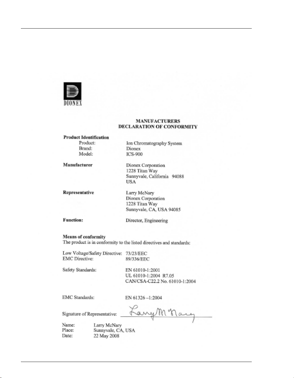
1.3.3 Declaration of Conformity
The cETLus and CE marks on the ICS-900 model/data label indicate that
the ICS-900 is in compliance with the following standards.
6 Doc. 065215-02 9/09
Page 15
2.1 Operating Features
2.1.1 Front Door and Top Cover
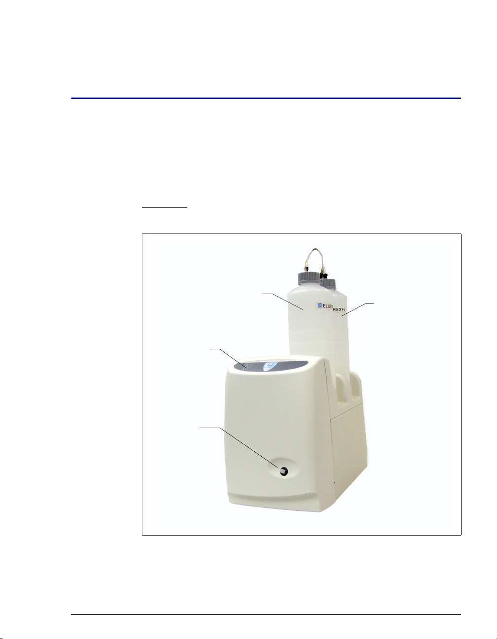
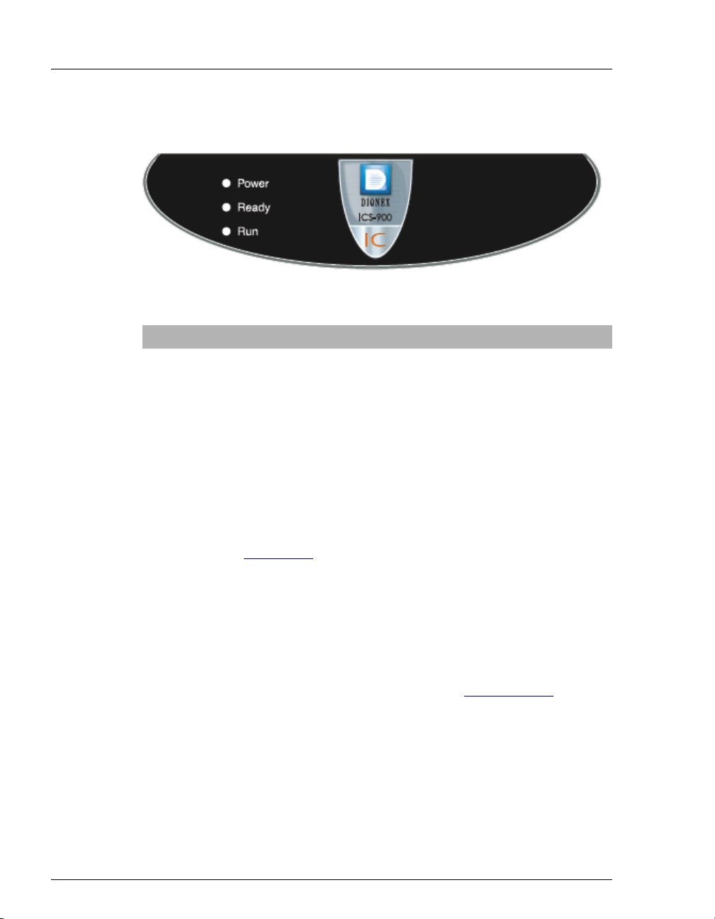
Figure 2-1 illustrates the front door and top cover of the ICS-900 Ion
Chromatography System (ICS-900).
2 • Description
Status LEDs
Injection
Port
Figure 2-1. ICS-900 Ion Chromatography System
Eluent Bottle
Regenerant
Bottle
Doc. 065215-02 9/09 7
Page 16
ICS-900 Operator’s Manual
LEDs
Three status LEDs (described below) are on the ICS-900 front door.
LED Label If On (Green) If Flashing
Power ICS-900 power is on Does not flash
Ready System check passed, but
sequence not yet started
(LED stays on until run starts
or sequence is aborted)
Run Running/acquiring data Error/alarm/fault (including
System check failed (occurs if
system check executes for
10 minutes without success)
injection valve position)
Other status information and alarm messages are displayed in the Audit
Trail in Chromeleon or Chromeleon Xpress. For a description of these
messages, see Section 4.1
Injection Port
The injection port can be connected to the injection valve inside the
ICS-900. The sample to be analyzed is injected into the injection port
using a syringe. For automated sample injections, the ICS-900 injection
valve can be connected to an autosampler, instead of to the injection port.
For more information about sample injection, see Section 3.11.5
Eluent and Regenerant Bottles
.
The ICS-900 top cover is molded to hold one eluent bottle assembly
(P/N 062510) and one regenerant bottle assembly (anion, P/N 068222;
cation, P/N 068223).
• Eluent carries the sample through the ICS-900 and facilitates the ion
separation process. The type of eluent used depends on the analyses
8 Doc. 065215-02 9/09
Page 17
performed. For example, an ICS-900 configured for anion analyses
r
uses carbonate eluent, while an ICS-900 configured for cation
analyses uses methanesulfonic acid (MSA) eluent.
• Regenerant renews the suppressor’s ability to suppress eluent
conductivity. An ICS-900 configured for anion analyses uses dilute
sulfuric acid regenerant. An ICS-900 configured for cation analyses
uses tetrabutylammonium hydroxide (TBAOH) regenerant. For more
information about suppressor regeneration, see Section 2.3.5
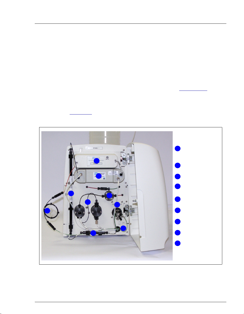
2.1.2 Component Mounting Panel
Figure 2-2 shows the components installed on the component panel
behind the ICS-900 front door.
1
2 • Description
.
Conductivity Cell
1
(Housed in DS5
Detection Stabilize
MMS 300
2
Suppressor
2
3
4
9
8
5
6
7
3
Separator Column
Pump Heads
4
Pressure
5
Transducer
Injection Valve
6
Tubing Chase
7
Guard Column
8
Backpressure
9
Tub ing
Figure 2-2. ICS-900 Component Mounting Panel
Doc. 065215-02 9/09 9
Page 18

ICS-900 Operator’s Manual
Conductivity Cell
The flow-through heated conductivity cell measures the electrical
conductance of analyte ions as they pass through the cell. A heat
exchanger inside the cell regulates the temperature to 40 °C (104 °F). The
cell is housed inside a DS5 Detection Stabilizer (P/N 067761). For details
about the conductivity cell and DS5 Detection Stabilizer, see
Section 2.3.1
MMS™ 300 MicroMembrane Suppressor
The MMS 300 suppressor reduces the eluent conductivity and enhances
the conductivity of the sample ions, thereby increasing detection
sensitivity. For details about the MMS 300 suppressor, see Section 2.3.4
Separator and Guard Columns
Both the separator and guard columns are packed with resin and perform
the separation of the sample ions. The main function of the guard column
is to trap contaminants and remove particulates that might damage the
separator column.
.
.
Pressure Transducer
The pressure transducer measures the system backpressure. See
Section 2.3.2
Pump Heads
for details about the pressure transducer.
The ICS-900 includes a dual-piston serial pump. The flow rate can be set
from 0.01 mL/min to 5.00 mL/min. However, for optimum performance,
set the flow rate to between 0.20 and 3.00 mL/min. Setting the flow rate
to 0.00 mL/min turns off the pump. For details about the pump, see
Section 2.3.1
Injection Valve
.
The injection valve is a six-port, electrically-activated valve. For details
about the injection valve, see Section 2.3.3
10 Doc. 065215-02 9/09
.
Page 19
Tubing Chase
The tubing chase routes tubing from the component panel, through the
ICS-900 interior, to the rear panel.
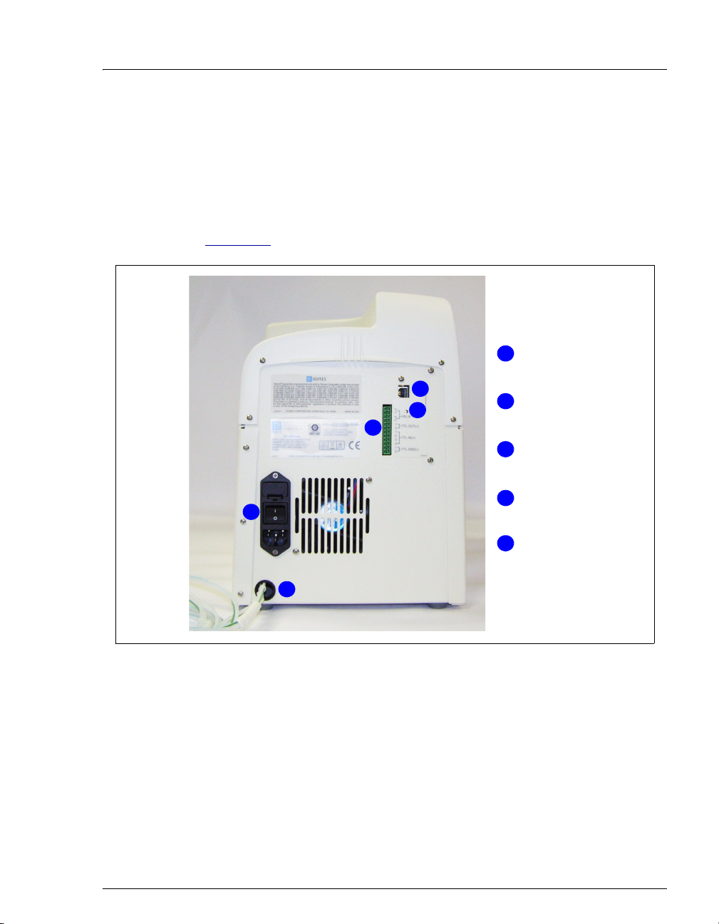
2.1.3 Rear Panel
Figure 2-3 illustrates the ICS-900 rear panel.
2 • Description
USB Connector
1
1
2
3
4
5
Link LED
2
TTL and Relay
3
Connector
Fuse Holder,
4
Power Switch, and
Power Receptacle
Plumbing and
5
Waste Lines
Figure 2-3. ICS-900 Rear Panel
USB Connector
The USB connector connects the ICS-900 to the PC on which
Chromeleon or Chromeleon Xpress is installed. For the standard system
configuration of one ICS-900 connected to a PC, connect a USB cable
between the USB connector on the ICS-900 and a USB port on the PC.
For detailed connection instructions, refer to the ICS-900 Ion
Chromatography System Installation Instructions (Document
Doc. 065215-02 9/09 11
Page 20
ICS-900 Operator’s Manual
No. 065214), provided on the Dionex Reference Library CD-ROM
(P/N 053891) and in the ICS-900 Ship Kit (P/N 067768).
Link LED
The Link LED indicates the communication status
between the ICS-900 and the PC on which
Link
Chromeleon or Chromeleon Xpress is installed.
LED Status Description
On The ICS-900 and the PC are linked, but no data is currently
being transmitted or received
Flashing The ICS-900 and the PC are linked and data is being
transmitted
Off The ICS-900 and the PC are not currently linked
TTL and Relay Connector
The TTL and Relay connector strip provides two TTL outputs, two relay
outputs, and four TTL inputs. The outputs can be used to control
functions in other TTL- or relay-controllable devices. The inputs can be
used to switch the injection valve position, turn the pump on and off, and
perform an autozero command. For connection instructions, see
Appendix C
Fuse Holder, Power Switch, and Power Receptacle
.
• The fuse holder contains two fast-blow IEC 127 fuses rated 3.15 A
(P/N 954745). For instructions on how to change the fuses, see
Section 5.13
.
• The power switch provides on/off control of power to the ICS-900.
• The power cord plugs into the IEC 320 three-prong receptacle.
The power supply cord is used as the main disconnect device. Make
sure the socket-outlet is located near the ICS-900 and is easily
accessible.
Le cordon d'alimentation principal est utilisé comme dispositif
principal de débranchement. Veillez à ce que la prise de base soit
située/installée près du module et facilement accessible.
12 Doc. 065215-02 9/09
Page 21

2 • Description
Das Netzkabel ist das wichtigste Mittel zur Stromunterbrechung.
Stellen Sie sicher, daß sich die Steckdose nahe am Gerät befindet und
leicht zugänglich ist.
Plumbing and Waste Lines
The following lines exit the ICS-900 through the tubing chase on the
lower left corner of the rear panel.
• Eluent
• Regenerant
• Cell outlet
• Waste (sample, regenerant, and pump priming)
Doc. 065215-02 9/09 13
Page 22
ICS-900 Operator’s Manual
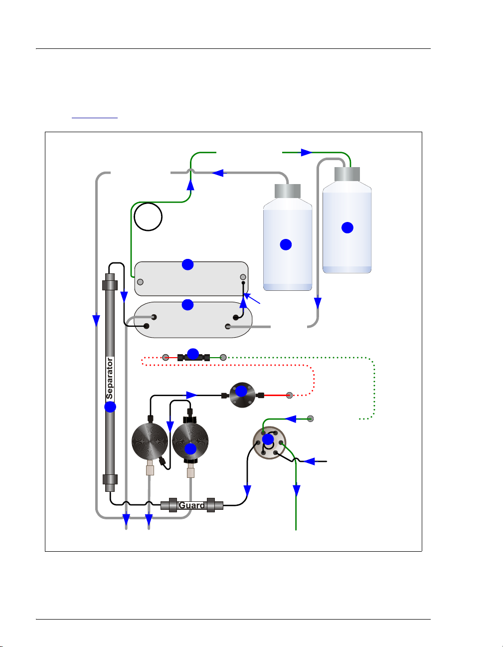
2.2 Fluid Schematic
Figure 2-4 shows the flow path through the ICS-900.
To pump inlet
From cell outlet
6
Backpressure Coil
(1 or 2, depending on
flow rate)
8
Conductivity Cell
(in DS5 Detection Stabilizer)
Regen Out Eluent Out
Eluent In
Secondary
7
MMS 300
Pulse Damper
4
Primary
2
Pump
Heads
Regen In
Transducer
Eluent
To cell inlet
To MMS
Regen In
Pressure
3
LP
5
CW
L
S
Injection
Valve
Regenerant
9
1
Eluent in
from pulse
damper
Sample in
To Waste
To Waste
Figure 2-4. ICS-900 Flow Schematic
14 Doc. 065215-02 9/09
Page 23
2 • Description
Liquid flows through the ICS-900 along the following flow path. Refer to
Figure 2-4
for the flow path number locations.
• Eluent from the eluent bottle is drawn into the pump . The pump pushes
the eluent through the pressure transducer , which measures the system
pressure, and through a pulse damper , which smooths minor pressure
1 2
3
4
variations from the pump to minimize baseline noise.
• The eluent then flows into the injection valve . After sample is loaded into
5
the sample loop and the injection valve is toggled to the Inject position, eluent
passes through the sample loop pushing the sample into the eluent stream.
• The eluent/sample mixture is pumped through the guard and separator
columns , where the ions are separated by the ion exchange process.
• The eluent/sample mixture then flows through the suppressor , which
suppresses the conductivity of the eluent and enhances the conductivity of the
analyte. Regenerant flows continuously through the suppressor, restoring the
ion exchange sites to their original state.
• The eluent/sample mixture then flows through the conductivity cell , where
the analytes are detected. A signal is produced and sent to Chromeleon or
Chromeleon Xpress software.
• Finally, the eluent flows out of the cell and into the regenerant bottle , where
it pressurizes the regenerant and forces it into the suppressor.
6
7
8
9
Doc. 065215-02 9/09 15
Page 24
ICS-900 Operator’s Manual
2.3 System Component Details
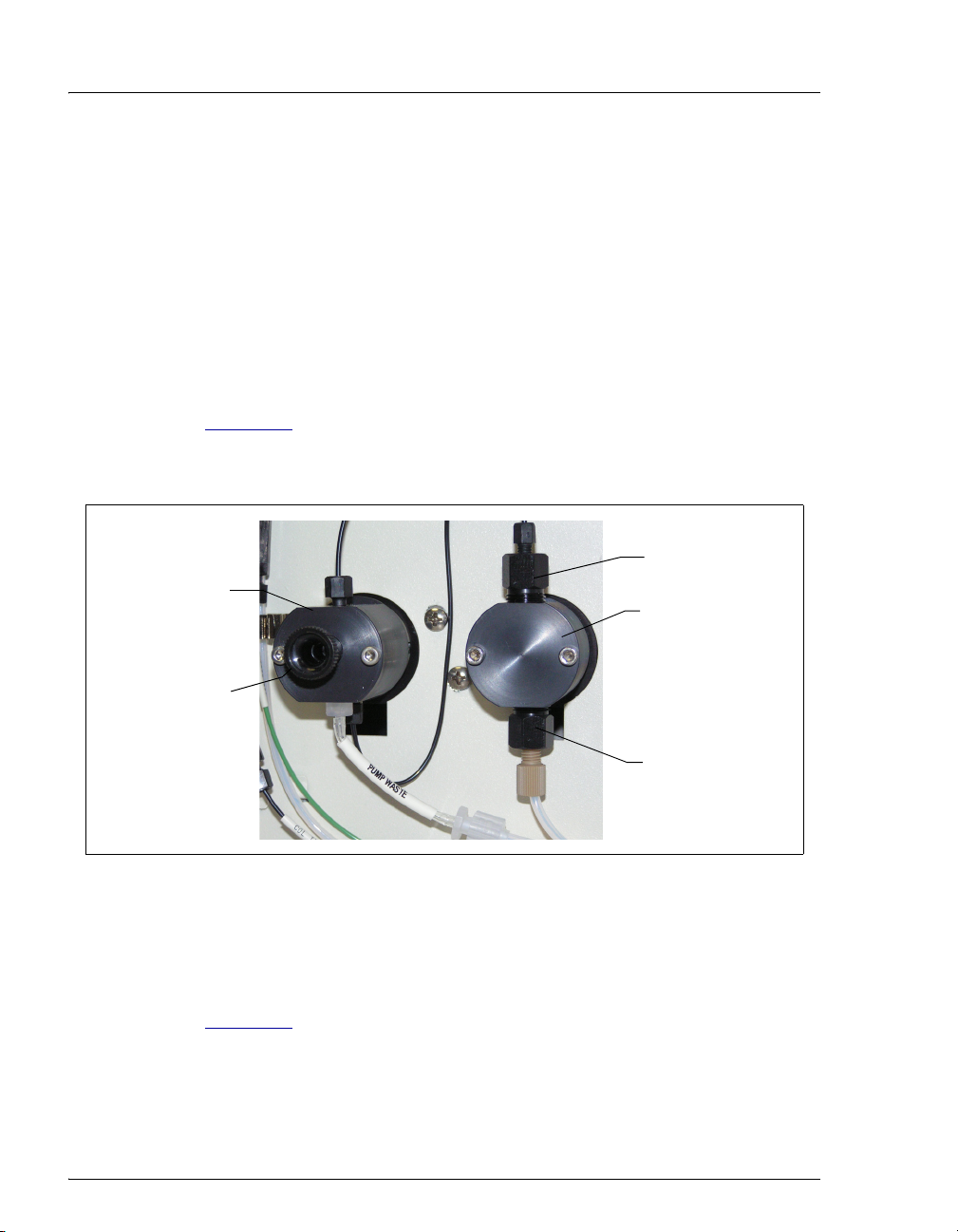
2.3.1 Pump
The ICS-900 pump is a microprocessor-based isocratic eluent delivery
system. Its variable speed, dual-piston series design ensures pulse-free
pumping for the most demanding applications.
Primary Pump Head
The primary pump head pumps eluent into the secondary head (see
Figure 2-5
pump, are located on the bottom (inlet) and top (outlet) of the primary
pump head.
Secondary
Pump Head
). The check valves, which prevent reverse flow through the
Outlet Check
Valve
Primary Pump
Head
Waste Valve
Inlet Check
Valve
Figure 2-5. ICS-900 Pump Components
Secondary Pump Head
The secondary pump head delivers eluent to the pressure transducer. The
waste valve is located on the front of the secondary pump head (see
Figure 2-5
).
To open the waste valve, turn the knob one-half turn counterclockwise.
When the waste valve is in the open position, all output is directed to
waste.
16 Doc. 065215-02 9/09
Page 25

2.3.2 Pressure Transducer
The pressure transducer measures the system pressure at the point that the
eluent flows from the pump head outlet check valve. Pressure readings
indicate that the pumping system is delivering smooth, accurate flow.
Pressure readings can be monitored from Chromeleon or Chromeleon
Xpress.
The system pressure should remain consistent (no more than a 3%
difference from one pressure reading to the next). High and low pressure
limits can be used to stop the pump flow if a limit is exceeded. The
pressure limits can be set from Chromeleon (in the Server Configuration
Properties dialog box or in the Chromeleon or Chromeleon Xpress
program). For troubleshooting information if a pressure limit is exceeded,
see Section 4.7
Pulse Damper
Flow output from the pressure transducer continues to the pulse damper,
which smooths minor pressure variations. From there, flow is directed to
the injection valve and then to the remainder of the chromatography
system.
.
2 • Description
Doc. 065215-02 9/09 17
Page 26
ICS-900 Operator’s Manual
C
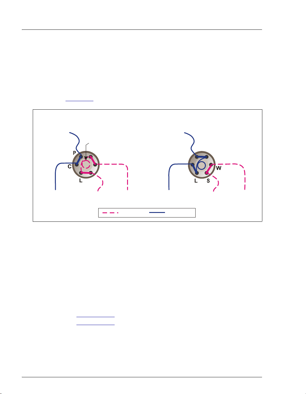
2.3.3 Injection Valve with Sample Loop
The injection valve is a six-port, electrically-activated Rheodyne valve. A
10 μL sample loop (P/N 042949) is installed on the valve at the factory.
The valve has two operating positions: Load and Inject. Eluent flows
through either the Load or Inject path, depending on the valve position.
From Pump
To Column
Figure 2-6
LOAD POSITIONINJE
shows flow schematics for the valve.
T POSITION
From Pump
Sample Loop
L
W
S
Sample In
Figure 2-6. Injection Valve Flow Schematics
To Waste
= Sample
= Eluent
P
C
L
Sample InTo Column
To Waste
• In the Load position, sample is loaded into the sample loop, where it
is held until injection. Eluent flows from the pump, through the valve,
and to the column, bypassing the sample loop. Sample flows from the
syringe or autosampler line (if installed), through the valve, and into
the sample loop. Excess sample flows out to waste.
• In the Inject position, sample is swept to the column for analysis.
Eluent flows from the pump, through the sample loop, and on to the
column, carrying the contents of the sample loop with it.
Section 3.11.2
Section 3.11.3
18 Doc. 065215-02 9/09
describes how to inject samples manually;
describes how to inject samples with an autosampler.
Page 27
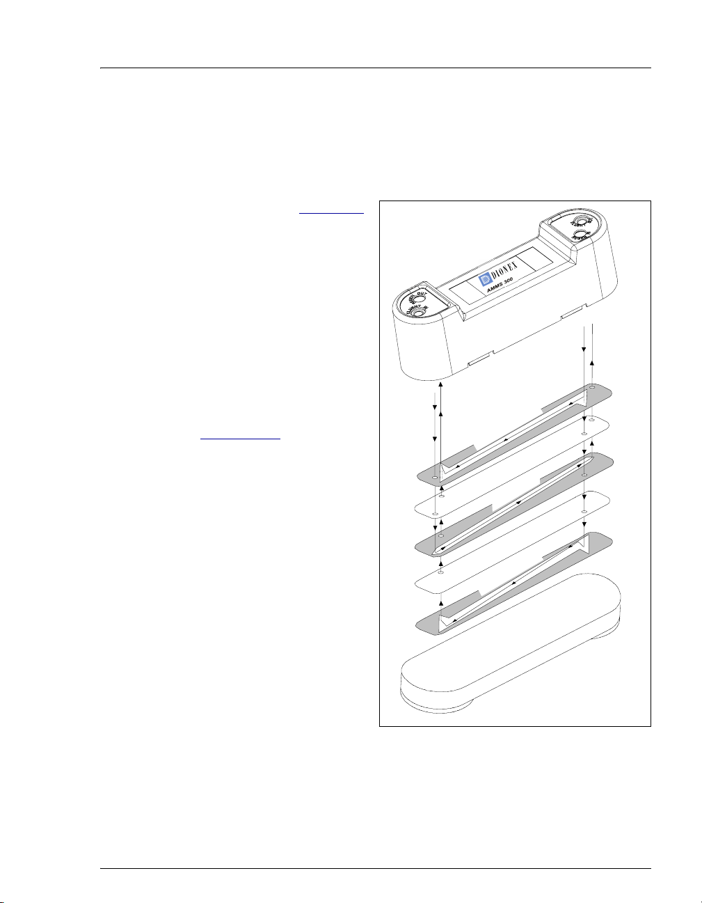
2.3.4 MMS 300 MicroMembrane Suppressor
E
T
The MMS 300 suppressor reduces the eluent conductivity and enhances
the conductivity of the sample ions, thereby increasing detection
sensitivity.
2 • Description
As illustrated in Figure 2-7
,
a constant flow of
regenerant over the
membrane continually
restores the suppression
ability of the MMS 300.
A process called
Displacement Chemical
Regeneration (DCR)
pushes regenerant from the
regenerant bottle through
the suppressor. See
Section 2.3.5
for details.
N
I
T
N
E
U
L
N
E
G
E
R
R
For more information about
the MMS 300, refer to the
suppressor manual.
Suppressor manuals are
included on the Dionex
Reference Library CDROM (P/N 053891).
m
m
-
4
U
O
T
N
E
U
L
E
N
I
N
E
G
E
R
T
U
O
n
e
e
r
c
S
t
n
a
r
e
n
e
g
e
n
a
h
c
x
E
n
o
I
n
e
u
l
E
n
a
h
c
x
E
n
o
I
a
r
e
n
e
g
e
R
e
n
a
r
b
m
e
M
e
g
n
e
e
r
c
S
t
e
n
a
r
b
m
e
M
e
g
n
e
e
r
c
S
t
n
Figure 2-7. MMS 300 Suppressor Flow
Doc. 065215-02 9/09 19
Page 28
ICS-900 Operator’s Manual
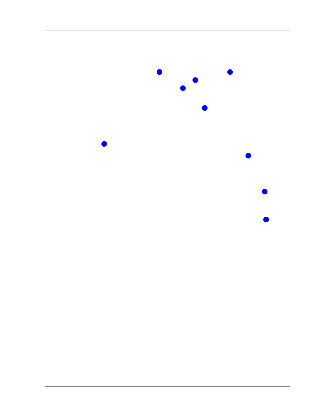
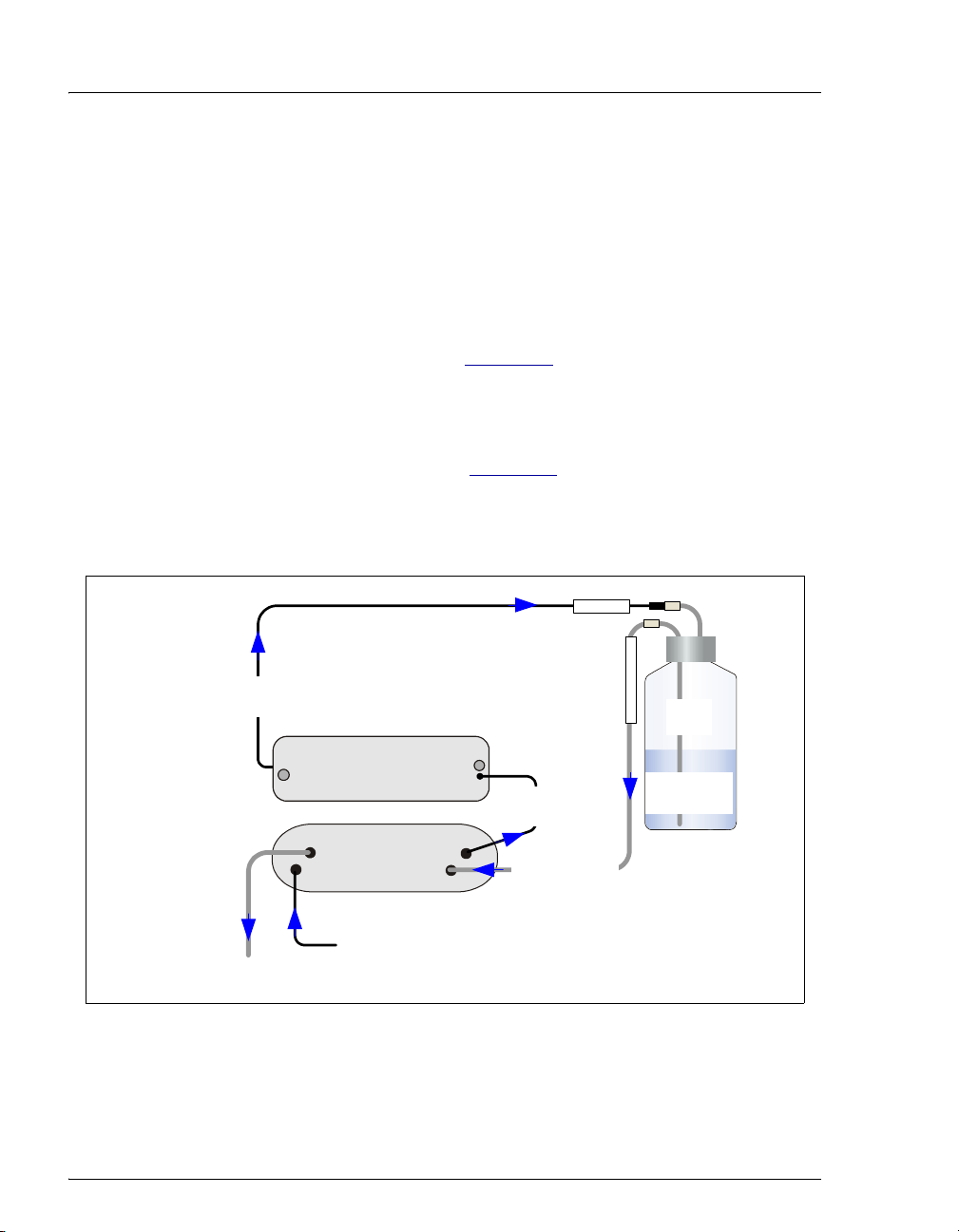
2.3.5 Displacement Chemical Regeneration (DCR)
Displacement Chemical Regeneration (DCR) is the process that restores
the ability of the MMS 300 suppressor to suppress eluent. In DCR, the
eluent that exits the cell is pumped into the regenerant bottle. The eluent
pressurizes the bottle and pushes the regenerant into the suppressor.
However, because the eluent is a different density than the regenerant, it
remains separate.
In the anion DCR process (see Figure 2-8
), the eluent is less dense than
the regenerant and it remains on the top of the bottle, forcing the
regenerant into the regenerant line at the bottom of the bottle and out into
the suppressor.
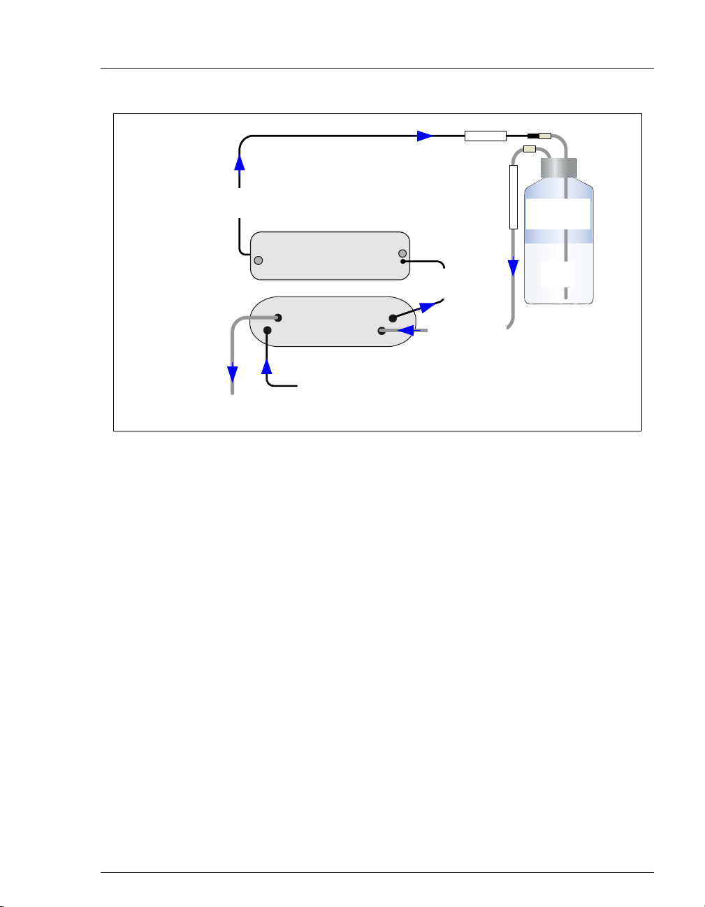
In the cation DCR process (see Figure 2-9
), the eluent is denser than the
regenerant and it flows to the bottom of the bottle. This displaces the
regenerant, pushing regenerant out of the regenerant line at the top of the
bottle and out into the suppressor.
Regen In
Used eluent out to
regenerant reservoir
(in DS5 Detection Stabilizer)
Regen Out Eluent Out
Eluent In
Conductivity Cell
AMMS 300
Regen In
Eluent
out to cell
Regenerant in
from reservoir
Used
Regen Bottle Out
Eluent
Anion
Regenerant
Eluent in from column
Regenerant out to waste
Figure 2-8. Anion ICS-900 Displacement Chemical Regeneration (DCR)
20 Doc. 065215-02 9/09
Page 29
Regen In
2 • Description
Used eluent out to
regenerant reservoir
Conductivity Cell
(in DS5 Detection Stabilizer)
Regen Out Eluent Out
Eluent In
Regenerant out to waste
CMMS 300
Regen In
Eluent in from column
Eluent
out to cell
Regenerant in
from reservoir
Cation
Regenerant
Regen Bottle Out
Used
Eluent
Figure 2-9. Cation ICS-900 Displacement Chemical Regeneration (DCR)
Connections to the regenerant bottle differ depending on whether the
system will run an anion or a cation application. Regenerant bottles for
each type of application are available (anion regenerant bottle assembly,
P/N 068222; cation regenerant bottle assembly, P/N 068223). For detailed
installation instructions, refer to the DCR Kit Installation Instructions
(Document No. 031664), provided on the Dionex Reference Library CDROM (P/N 053891).
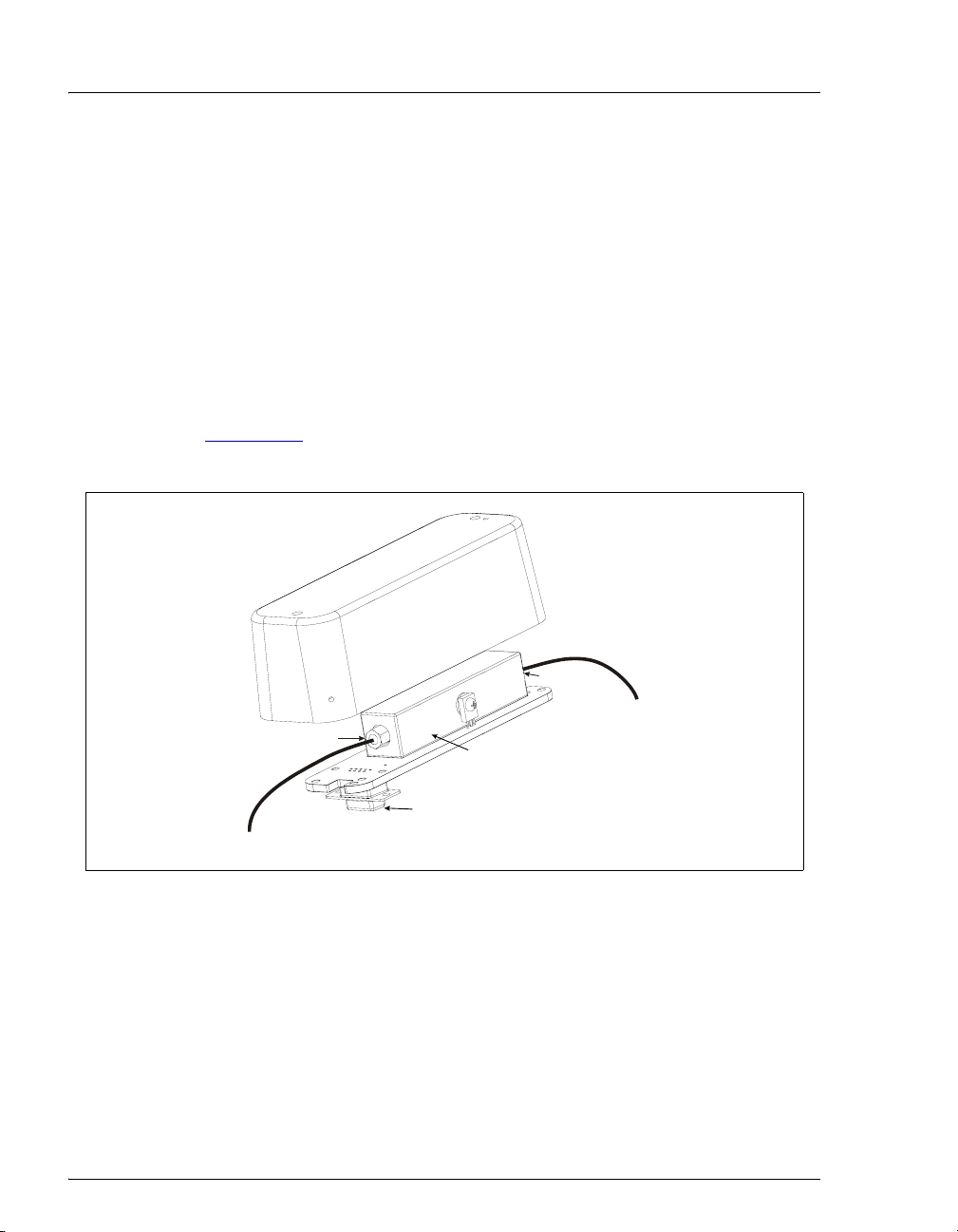
2.3.6 Conductivity Cell and DS5 Detection Stabilizer
The flow-through heated conductivity cell contains two 316 stainless steel
electrodes that are permanently sealed into the PEEK cell body. The cell
measures the electrical conductance of analyte ions as they pass through
the cell.
Temperature directly affects the conductivity of a solution. For example,
laboratory heating and air conditioning systems can cause a regular slow
cycling in the baseline. This, in turn, can affect the reproducibility of an
analysis. The higher the conductivity, the more pronounced the effect.
Doc. 065215-02 9/09 21
Page 30
ICS-900 Operator’s Manual
t
In ion analysis, the effect of temperature variation is minimized by
suppressing eluent conductivity. Built-in preset temperature
compensation also ensures that there is no major change in the baseline or
in peak heights. Temperature compensation
stability.
Direct conductive heating is used in the ICS-900 conductivity cell to
provide temperature control and compensation. A heat exchanger inside
the ICS-900 cell regulates the temperature. All data is collected at 40 °C
(104 °F).
The cell is housed inside a DS5 Detection Stabilizer (P/N 067761) (see
Figure 2-10
temperature.
), which helps to insulate the cell from fluctuations in ambient
further improves baseline
r
e
z
i
l
i
b
a
t
S
n
o
i
t
c
e
t
e
D
5
S
D
Cell Inlet
From suppressor
Cell Outlet
To r egenerant reservoir
Conductivity Cell
Connector to component
mounting panel
ELUENT OUT por
Figure 2-10. Conductivity Cell and DS5 Detection Stabilizer
The conductivity cell has two detection limit ranges: 0 to 500
10,000
for the application. The default range of 0 to 500
μS. Select the range depending on the expected detector readings
μS is appropriate for
μS or 0 to
most applications. The detection limit range is set in the Properties dialog
box of the Chromeleon Server Configuration program. For details, refer
to the ICS-900 Ion Chromatography System Installation Instructions
(Document No. 065214), provided on the Dionex Reference Library CDROM (P/N 053891) and in the ICS-900 Ship Kit (P/N 067768).
22 Doc. 065215-02 9/09
Page 31
2 • Description
2.4 Chromeleon and Chromeleon Xpress Software
The ICS-900 is controlled by a PC configured with Chromeleon Chromatography
Management System or Chromeleon Xpress. Chromeleon
Management System provides complete instrument control, data acquisition, and
data management. Chromeleon Xpress provides real-time control and monitoring
of Dionex chromatography instruments, but does not include data management
capabilities.
2.4.1 The Panel Tabset
The Chromeleon and Chromeleon Xpress panel tabset provides a
centralized location for controlling system functions. A panel tabset for
an ICS-900 system typically includes the following Control panels:
• An ICS-900 Control panel (see Figure 2-11) provides access to
ICS-900 functions. The label on the tab for this panel is the name of
the timebase in which the ICS-900 is configured.
Chromatography
Figure 2-11. ICS-900 Panel on the Panel Tabset
Doc. 065215-02 9/09 23
Page 32

ICS-900 Operator’s Manual
• A Sequence Control provides controls for defining and running
sequences (groups of sample injections to be analyzed in the order in
which they are listed).
• A Status panel shows the overall system status.
• An autosampler panel provides access to autosampler functions.
This panel is present only if the timebase in which the ICS-900 is
configured includes an autosampler.
To open the panel tabset, use one of the methods below:
• If Chromeleon is installed,
start Chromeleon and click
the Default Panel Tabset
toolbar button, or select
View > Default Panel
Tab se t.
• If Chromeleon Xpress is
installed, start the application; this automatically displays the
ICS-900 panel tabset.
2.4.2 Software Control Modes
Two modes of software control are available: direct control and
programmed control.
• With direct control, you select operating parameters and commands
from the Control panels. Direct control commands are executed as
soon as they are entered. See Section 3.11.2
control.
for details about direct
• With programmed control, you create a list of control commands to
be executed in chronological order. Programs can be created
automatically (with the help of a software wizard). See Section 3.11.3
for details about programmed control.
24 Doc. 065215-02 9/09
Page 33

2 • Description
2.4.3 System Wellness and Predictive Performance
System Wellness monitors the overall “health” of a chromatographic
system. It provides built-in diagnostic and calibration features that help
prevent unscheduled system shutdowns and assure reliable operation of
system devices. For details about System Wellness, see Section 5.1
Predictive Performance provides functions for monitoring the usage of
replaceable parts and for planning service procedures. Predictive
Performance lets you monitor the following functions:
• The number of hours the ICS-900 has been in use
• The number of times the injection valve has cycled
• The number strokes performed by the pump pistons
• The estimate of the amount of wear to the piston seal
• The volume of eluent pumped through the suppressor and column
You can set limits for injection valve cycles, piston strokes, piston seal
wear, suppressor usage, and column usage. Two limits can be set for each
parameter. When the first limit is reached, a warning message is displayed
in the Chromeleon or Chromeleon Xpress Audit Trail. When the second
limit is reached, an error message is displayed in the Audit Trail. After
replacing a part, reset the limit counters to zero.
.
Different applications cause different rates of wear on the consumable
parts in your instrument. Experience will help you determine the
appropriate limits to set to predict when the next maintenance will be
required.
Predictive Performance commands and parameters are available in the
Commands dialog box in Chromeleon or Chromeleon Xpress. To open
the Commands dialog box, press F8. Expand the list of commands under
Pump_ECD and scroll to the Predictive Performance commands
Doc. 065215-02 9/09 25
Page 34

ICS-900 Operator’s Manual
(InjectValveCycles, PumpPistonStrokes, SealWear,
SuppressorVolume, ColumnVolume) (see Figure 2-12
).
Figure 2-12. Predictive Performance Commands: InjectValveCycles
If you do not wish to receive these warning or error messages, you can
disable them by setting the Warning and Limit parameter for each
Predictive Performance function to Off.
26 Doc. 065215-02 9/09
Page 35

3 • Operation and Maintenance
This chapter describes routine operating and maintenance procedures for the ICS900 Ion Chromatography System (ICS-900).
3.1 Operation Overview
Figure 3-1 illustrates the basic steps for routine operation of the ICS-900.
Turn on the ICS-900
power
Connect to
Chromeleon
Prepare the eluent
and regenerant
Prime the pump
Equilibrate the
system
Prepare samples
Process samples
Figure 3-1. ICS-900 Operation Flow Chart
Doc. 065215-02 9/09 27
Page 36

ICS-900 Operator’s Manual
3.2 Turning On the ICS-900 Power
Press the power switch on the ICS-900 rear panel (see Figure 2-3) to turn on the
system power. These are the conditions at power-up:
• The pump is off.
• The injection valve is in the Load position.
• The conductivity detector begins reading the current conductivity.
3.3 Connecting to Chromeleon or Chromeleon Xpress
1. Turn on the PC.
2. Start the Chromeleon Server, if it is not already running.
a. Check the Chromeleon Server Monitor icon on the Windows taskbar.
• When the server is running, the icon is gray .
• When the Server is not running, the icon is crossed out in red . To
start the server, right-click the icon and select Start Server.
b. If the Server Monitor icon is not on the Windows taskbar, click Start and
select All Programs (or Programs) > Chromeleon > Server Monitor.
The Server Monitor opens. Click Start to start the server.
3. To start the Chromeleon client, click Start and select All Programs (or
Programs) > Chromeleon > Chromeleon.
4. If Chromeleon is installed, display
the panel tabset by selecting View >
Default Panel Tabset or by
clicking the Default Panel Tabset
toolbar button.
If Chromeleon Xpress is installed,
starting the application
automatically displays the panel tabset.
5. To display the ICS-900 Control panel, select the tab labeled with the ICS-900
timebase name (see Figure 3-2
28 Doc. 065215-02 9/09
).
Page 37

3 • Operation and Maintenance
Figure 3-2. ICS-900 Control Panel on Panel Tabset
3.4 Preparing the Eluent
1. Prepare the eluent. For instructions refer to the column manual. Column
manuals are included on the Dionex Reference Library CD-ROM (P/N
053891).
2. Fill the eluent bottle with the prepared eluent, insert the stopper assembly
tubing into the bottle, and hand tighten the cap.
Set the Eluent Level
After filling the bottle, move the Eluent Remaining slider on the ICS-900
Control panel (see Figure 3-3) to indicate the volume of liquid in the bottle.
The ICS-900 determines the eluent usage by monitoring the flow rate and the
length of time the pump is on. As the eluent is used up, the ICS-900 updates the
Eluent Remaining slider and gauge. A warning appears in the Audit Trail when
the level falls below 200 mL, and then again when the level falls bellow 100 mL.
Doc. 065215-02 9/09 29
Page 38

ICS-900 Operator’s Manual
For the eluent level to be accurate, you must enter the level each time
the bottle is filled.
Figure 3-3. Setting the Eluent Level
3.5 Preparing the Regenerant
After filling the eluent
bottle, move the slider to
indicate the volume of
liquid in the bottle
Note: The Eluent
Remaining slider and
gauge are updated as the
liquid is used up.
The type of regenerant used with the ICS-900 depends on the type of analysis to
be run. A dilute sulfuric acid regenerant is used for anion analyses; a
tetrabutylammonium hydroxide (TBAOH) regenerant is used for cation analyses.
Follow the instructions below to prepare either anion or cation regenerant.
Use ASTM Type I (18 megohm-cm) filtered and deionized water to prepare the
regenerant.
1. Verify that you have the correct regenerant bottle assembly (P/N 068222 for
anion analyses; P/N 068223 for cation analyses):
• For anions, verify that the cap is labeled ANION and the REGEN BOTTLE
line extends to the bottom of the bottle.
OUT
• For cations, verify that the cap is labeled CATION and the REGEN BOTTLE
OUT line extends only about 1 cm (0.4 in) into the bottle.
2. Rinse the regenerant bottle with deionized water.
3. Fill the bottle about halfway with deionized water.
30 Doc. 065215-02 9/09
Page 39
3 • Operation and Maintenance
4. Determine the regenerant concentration required for the application. To
estimate the regenerant concentration required for an eluent strength, use the
following formulas:
Anion Regenerant Concentration = (mM eluent) x 2
Cation Regenerant Concentration = (mM eluent) x 5
For example, if you are using 20 mM methanesulfonic acid (MSA) as the
eluent for cation analysis, use a regenerant concentration of 100 mM
tetrabutylammonium hydroxide (TBAOH).
For additional details, refer to the Displacement Chemical Regeneration
(DCR) kit installation instructions and the suppressor manual.
5. Empty the required amount of concentrate (sulfuric acid for anions; TBAOH
for cations) into the bottle.
For acid concentrates (such as the anion regenerant), always pour the
concentrate into deionized water, not into the empty bottle.
Pour les concentrés acides (comme le régénérant anionique), versez toujours le
concentré dans de l'eau désionisée et non dans le réservoir vide.
Gießen Sie säurehaltige Konzentrate (beispielsweise den Anionregenerenten)
das Konzentrat immer in entionisiertes Wasser und nicht in den leeren Behälter.
6. Fill the bottle almost to the top with deionized water and then place the bottle
in the tray on the top of the ICS-900.
NOTE To avoid staining the ICS-900, be careful not to spill
TBAOH on the instrument.
7. Using the concentrate bottle, pour additional deionized water into the bottle
until it is completely filled to the top. If a few drops spill over, then it is full
enough.
The regenerant bottle must be filled all the way to the top at all times.
8. Insert the stopper assembly tubing into the bottle and hand-tighten the cap.
9. Invert the bottle three or four times to disperse the concentrate.
Doc. 065215-02 9/09 31
Page 40

ICS-900 Operator’s Manual
After the analysis begins, do not mix the contents of the regenerant bottle.
10.Verify that the liquid lines from the ELUENT and REGEN bottles are
connected to the corresponding lines from the ICS-900 (see Figure 3-4
ELUENT Bottle Out
).
Figure 3-4. Eluent and Regenerant Bottle Liquid Line Connections
3.6 Priming the Pump
Prime the pump if the eluent has been changed, the eluent line contains air, or the
pump heads are dry (for example, after servicing).
NOTE If the eluent line is empty or the pump heads are
completely dry, you can use a 10 cc syringe (P/N 054578)
to prime the pump (see page 34
REGEN
Bottle In
REGEN Bottle Out
).
1. Verify that the ELUENT and REGEN bottles are filled, the bottle caps are
installed and hand-tightened, and the liquid lines are connected to the bottles.
2. Verify that the waste lines are directed to a waste container.
32 Doc. 065215-02 9/09
Page 41
3 • Operation and Maintenance
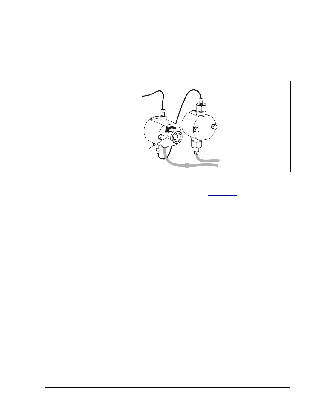
3. Open the waste valve on the secondary (left) pump head by turning the knob
one-half turn counterclockwise (see Figure 3-5
eluent flow path to waste and eliminates backpressure.
Secondary
Pump Head
Waste Valve
(Open)
Figure 3-5. Priming the Pump
). Opening the valve directs the
4. Click
Prime on the ICS-900 Control panel (see Figure 3-2), or open the
Commands dialog box (press F8), select the Pump command, and select the
Prime option. The pump will begin pumping at approximately 3 mL/min.
5. Continue priming the ICS-900 until no air bubbles are exiting the pump waste
line.
6. Click
Pump Off.
7. Close the waste valve. Do not overtighten. The pump is now ready for
operation.
NOTE A convenient way to verify that the waste valve is closed
is to select the pump flow rate required for your
application, turn on the pump, and then close the valve.
The pressure should rise to the value expected for the
application and quickly stabilize.
Doc. 065215-02 9/09 33
Page 42
ICS-900 Operator’s Manual
Priming the Eluent Line with a Syringe (Optional)
A syringe can be used to facilitate priming when the eluent line is empty or the
pump heads are completely dry.
1. Verify that the pump is turned off.
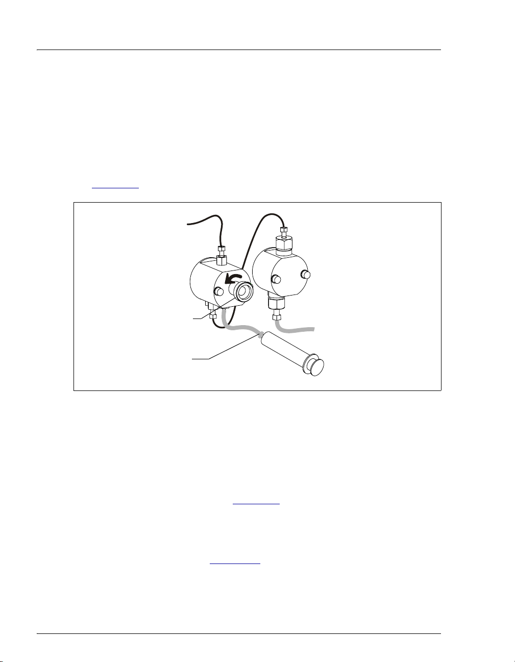
2. Disconnect the waste line from the luer fitting on the secondary (left) pump
head and connect a 10 mL syringe (P/N 054578) to the luer fitting (see
Figure 3-6
).
Secondary
Pump Head
Waste Valve
(Open)
Luer Fitting
Figure 3-6. Priming the Eluent Lines
10 mL Syringe
(P/N 054578)
3. Open the waste valve by turning it one-half turn counterclockwise.
4. Draw the syringe back to begin removing air from the flow path.
NOTE When the line already contains liquid, the syringe will be
difficult to draw back. In this case, prime with the prime
command only (see Section 3.6
).
5. When a small amount of liquid enters the syringe, remove the syringe from
the luer fitting, and reconnect the waste line to the luer fitting.
6. Follow the instructions in Section 3.6
34 Doc. 065215-02 9/09
to finish priming.
Page 43

3.7 Equilibrating the System
1. Turn on the pump and run at the flow rate recommended for the column.
2. Allow the system to equilibrate. The ICS-900 Control panel displays the
background conductivity (the conductivity of the eluent without the offset
performed by the autozero command).
3. Offset the background and zero the conductivity reading by clicking the
Autozero
4. Monitor the system pressure to make sure it is at the expected pressure for the
installed column (refer to the column manual for details) and is stable.
Column manuals typically provide pressure specifications for systems that do
not include a guard column. Expect the ICS-900 system pressure (with a
guard column) to be 15% to 20% higher than the specification in the column
manual.
• If the pressure is less than expected, air may be trapped in the system.
button on the ICS-900 Control panel.
Release the air by temporarily removing the pump fitting (P) on the
injection valve. Allow the air to escape, and then reconnect the fitting.
3 • Operation and Maintenance
• If the pressure is too high, there may be a restriction in the system
plumbing. Refer to the Section 4.7
5. Check for leaks in the regenerant bottle.
6. Check that liquid is flowing out of the suppressor
7. Monitor the baseline conductivity. In general, it should be <30
set up for anion analyses, and <2
Equilibration time varies and it can take some time to reach these expected
values.
If the conductivity is too high, see Section 4.12
information. If the baseline is drifting or has excessive “noise” (large
fluctuations in readings), see Section 4.13
μS for a system set up for cation analyses.
3.8 Verifying Operational Status
After the system has equilibrated, verify the actual pump pressure and stability by
monitoring the pump pressure. Record the short-term pressure fluctuations; they
should be less than 0.13 MPa (20 psi). If the pressure fluctuates by more than this
amount, prime the pump (see Section 3.6
for troubleshooting information.
REGEN OUT waste line.
μS for a system
for troubleshooting
.
).
Doc. 065215-02 9/09 35
Page 44

ICS-900 Operator’s Manual
3.9 Configuring Standby Mode
You can configure the ICS-900 to enter standby mode after a period of inactivity
(a period of time in which no data collection and no input from Chromeleon or
Chromeleon Xpress has occurred). In standby mode, the pump flow rate is
reduced.
To configure standby mode:
1. Start the Chromeleon Server Configuration program (click Start on the
Windows taskbar and select All Programs (or Programs) > Chromeleon >
Server Configuration).
2. Right-click the ICS-900 device in the timebase and select Properties.
3. Click Options (see Figure 3-7
Figure 3-7. ICS-900 Properties Dialog Box: Options Tab Page
4. Enter the desired Standby Flow Rate and select the Inactivity Time Out
Period. If you select (0, Off), the ICS-900 does not enter standby mode when
it is idle.
To cancel standby mode and return the pump to the normal flow rate, either turn
on the pump from the ICS-900 Control panel or start a new sequence.
).
36 Doc. 065215-02 9/09
Page 45

3.10 Preparing Samples
NOTE Sample preparation can be performed while the system
is equilibrating.
3.10.1 Collecting and Storing
Collect samples in high density polyethylene containers that have been
thoroughly cleaned with ASTM Type I (18 megohm-cm) filtered and
deionized water. Do not clean containers with strong acids or detergents
because these will leave traces of ions on the container walls. The ions
may interfere with the analysis.
If samples will not be analyzed on the day they are collected, filter them
through clean 0.45 μm filters immediately after collection; otherwise,
bacteria in the samples may cause the ionic concentrations to change over
time. Refrigerating the samples at 4
eliminate, bacterial growth.
Analyze samples containing nitrite or sulfite as soon as possible. Nitrite
oxidizes to nitrate, and sulfite to sulfate, thus increasing the measured
concentrations of these ions in the sample. In general, samples that do not
contain nitrite or sulfite can be refrigerated for at least one week with no
significant changes in anion concentrations.
3 • Operation and Maintenance
°C (39 °F) will reduce, but not
3.10.2 Pretreating
Analyze rainwater, drinking water, and air particulate leach solutions
directly with no sample preparation (other than filtering and possibly
diluting).
Filter groundwater and wastewater samples through 0.45 μm filters
before injection, unless samples were filtered after collection.
A Dionex High Pressure Inline Filter (P/N 044105) is available for
removing particulates down to 0.45 micron from samples. Connect the
inline filter between the autosampler outlet and the sample inlet port on
the injection valve. For details, see the printed installation instructions
provided with the inline filter.
Before injection, pretreat samples that may contain high concentrations of
interfering substances by putting them through Dionex OnGuard™
Doc. 065215-02 9/09 37
Page 46

ICS-900 Operator’s Manual
cartridges. For instructions, refer to Installation and Troubleshooting
Guide for OnGuard Cartridges (Document No. 032943). The manual is
included on the Dionex Reference Library CD-ROM (P/N 053891).
3.10.3 Diluting
Because the concentrations of ionic species in different samples can vary
widely from sample to sample, no single dilution factor can be
recommended for all samples of one type. In some cases (for example,
many water samples), concentrations are so low that dilution is not
necessary.
Use eluent or ASTM Type I (18 megohm-cm) filtered and deionized
water to dilute the sample. When using carbonate eluents, diluting with
eluent minimizes the effect of the water dip at the beginning of the
chromatogram. If you dilute the sample with eluent, also use eluent from
the same lot to prepare the calibration standards. This is most important
for fluoride and chloride, which elute near the water dip.
To improve the accuracy of early eluting peak determinations, such as
fluoride, at concentrations below 50 ppb, dilute standards in eluent or
spike the samples with concentrated eluent to minimize the water dip. For
example, spike a 100 mL sample with 1.0 mL of a 100 X eluent
concentrate.
38 Doc. 065215-02 9/09
Page 47

3.11 Processing Samples
3.11.1 Overview
Samples can be run manually (one at a time), or they can be grouped and
run automatically in batches. Figure 3-8
manual and batch sample processing.
3 • Operation and Maintenance
shows the typical steps for
Manual Sample
Processing
Load the sample
Autozero
Start data
acquisition
Inject the sample
Monitor
chromatogram
Stop data
acquisition
Batch Sample
Processing
Create a program*
Create a sequence
Load the
sequence
Start the batch
*Includes commands
for sample loading,
autozero, injection,
and data acquisition.
Figure 3-8. Sample Processing Overview
Doc. 065215-02 9/09 39
Page 48

ICS-900 Operator’s Manual
3.11.2 Manually Processing Samples
To manually process a sample, select operating parameters and
commands from the Chromeleon or Chromeleon Xpress panel tabset.
Commands are executed as soon as they are entered.
Summary of Manual Sample Processing
1. Complete the instructions in Section 3.2 through Section 3.10 to
prepare the ICS-900 for operation and to prepare the sample for
processing.
2. Load the sample into the injection valve sample loop with an
autosampler (see Section 3.11.4
) or a syringe (see Section 3.11.5).
3. On the ICS-900 Control panel, click the Autozero
button.
4. On the Sequence Control panel, click the Acq On button (or click
the Acquisition On/Off button on the Chromeleon toolbar).
5. Switch the injection valve to the Inject position. The method used to
switch the injection valve depends on whether you are using an
autosampler (see Section 3.11.4
) or a syringe (see Section 3.11.5).
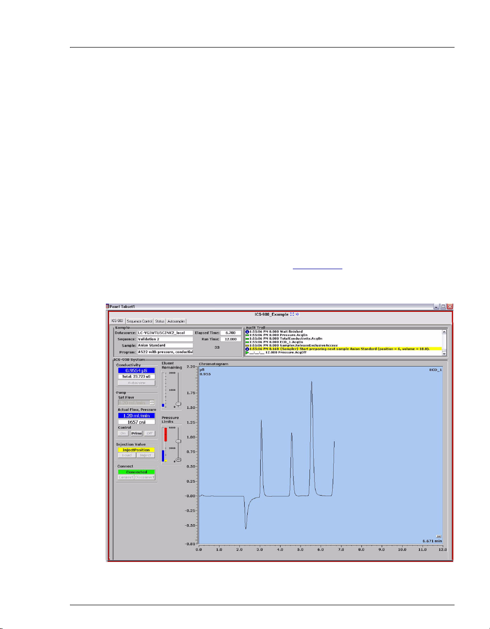
6. The signal plot is displayed on the ICS-900 Control panel (see
Figure 3-9
). Monitor the chromatogram and when sample data has
been collected, click the Acq Off button on the Sequence Control
40 Doc. 065215-02 9/09
Page 49

3 • Operation and Maintenance
panel (or click the Acquisition On/Off button on the Chromeleon
toolbar).
Figure 3-9. Manual Data Acquisition
Saving Manual Data
NOTE Chromeleon Xpress does not allow data to be saved.
If you are using Chromeleon, data from manual processing is saved in the
manual sequence under the timebase folder in the local datasource.
To save the data from a manual run:
1. Select the manual folder and select File>Save As.
2. Enter a new name for the sequence.
3. Select the Save raw data check box.
Doc. 065215-02 9/09 41
Page 50

ICS-900 Operator’s Manual
4. Click Save.
3.11.3 Automatically Processing Samples (Batch Processing)
You can use Chromeleon or Chromeleon Xpress to create a list of samples
(a sequence) to be processed automatically. For each sample, the
sequence includes the following:
• A program with commands and parameters for controlling the
ICS-900 and autosampler (if installed), and for acquiring sample data.
• A quantification method for peak identification and area
determination. The quantification method is not included with
Chromeleon Xpress.
• Additional sample processing parameters (sample name, sample type,
injection volume, etc.).
After creating the sequence, you can start batch processing.
Summary of Automatic Sample Processing
1. Complete the instructions in Section 3.2 through Section 3.10 to
prepare the ICS-900 for operation and to prepare the samples for
processing.
2. If an autosampler is installed, prepare and fill the sample vials and
place them in the autosampler tray or cassette. Refer to the
autosampler manual for detailed instructions. Autosampler manuals
are provided on the Dionex Reference Library CD-ROM
(P/N 053891).
3. If an autosampler is not installed, load the sample into the injection
valve sample loop through the sample port on the ICS-900 front door
(see Section 3.11.5
4. Use the Application Wizard to specify a program and quantitation
method, and create a sequence:
a. On the Sequence Control panel, click Application Wizard.
).
42 Doc. 065215-02 9/09
Page 51

3 • Operation and Maintenance
b. Select an application template from the list (see Figure 3-10).
Figure 3-10. Application Wizard
c. Click Next> and select the in a new sequence via Sequence
Wizard option.
d. Click Next> to go to the Sequence Wizard.
e. Complete the steps in the Sequence Wizard, adding the desired
number of samples and standards to the list. For help, click the
Help button on the Sequence Wizard page.
After you click Finish, a sequence is created and a program
appropriate for the selected application is copied to the sequence. If
you are using Chromeleon, a quantification method is also copied to
the sequence
.
5. Load the sequence and start batch processing:
a. On the Sequence Control panel, click Load Sequence.
b. Select the sequence created in Step 4
and click Open.
c. Click Start Batch.
Doc. 065215-02 9/09 43
Page 52

ICS-900 Operator’s Manual
3.11.4 Loading and Injecting Samples with an Autosampler
1. Verify that the autosampler output line is connected to port S (5) on
the injection valve. Direct the injection valve waste line as required
for the installed autosampler model.
For details about connecting an autosampler, refer to the ICS-900
Installation Instructions (Document No. 065214) and the autosampler
operator’s manual. The manuals are included on the Dionex
Reference Library CD-ROM (P/N 053891). The ICS-900 Installation
Instructions are also included in the ICS-900 Ship Kit (P/N 067768).
2. Prepare and fill the sample vials and place them in the autosampler
tray or cassette. Refer to the autosampler manual for detailed
instructions.
3. Use one of the following methods to load sample into the injection
valve sample loop and inject it onto the column:
• Automatically: Include the Load and Inject commands in a
Chromeleon or Chromeleon Xpress program. See the examples in
Section 3.11.6
processing samples.
. See Section 3.11.3 for details about automatically
• Manually with an AS40: Start the AS40 load cycle (either
manually or with a relay). When the AS40 load cycle is complete,
click the Inject button on the ICS-900 Control panel (see
Figure 3-11
processing samples.
Figure 3-11. ICS-900 Control Panel Load and Inject Buttons
). See Section 3.11.2 for details about manually
• Manually with an AS or AS-DV: Click the Inject icon on the
Chromeleon tool bar or select Control>Inject. On the Inject
dialog box, enter the Position and Vo lu me and click OK.
44 Doc. 065215-02 9/09
Page 53

3 • Operation and Maintenance
Autosampler Setup Notes
Follow the steps below to verify that the ICS-900 injection valve is
controlled by the correct device.
1. Open the Chromeleon Server Configuration program.
2. Open the ICS-900 Properties dialog box and click Inject Valve.
3. Under Controlled by, check the device selected for
Pump_InjectValve:
• For an AS or AS-DV, verify that the AS is shown (see
Figure 3-12
).
Figure 3-12. ICS-900 Properties: Inject valve controlled by AS
• For an AS40, verify that the ICS-900 is shown (see Figure 3-13).
Figure 3-13. ICS-900 Properties: Inject Valve Controlled by ICS-900
4. To change the controlling device, select the Pump_InjectValve name
and press the F2 key. On the Device Configuration dialog box, select
the correct device from the Controlled By list. Click OK.
5. For an AS40, also verify that there is a relay connection from the
AS40 Load relay to the ICS-900 RELAY OUT 1. Refer to the
connection instructions in Section C.5
Doc. 065215-02 9/09 45
for details.
Page 54

ICS-900 Operator’s Manual
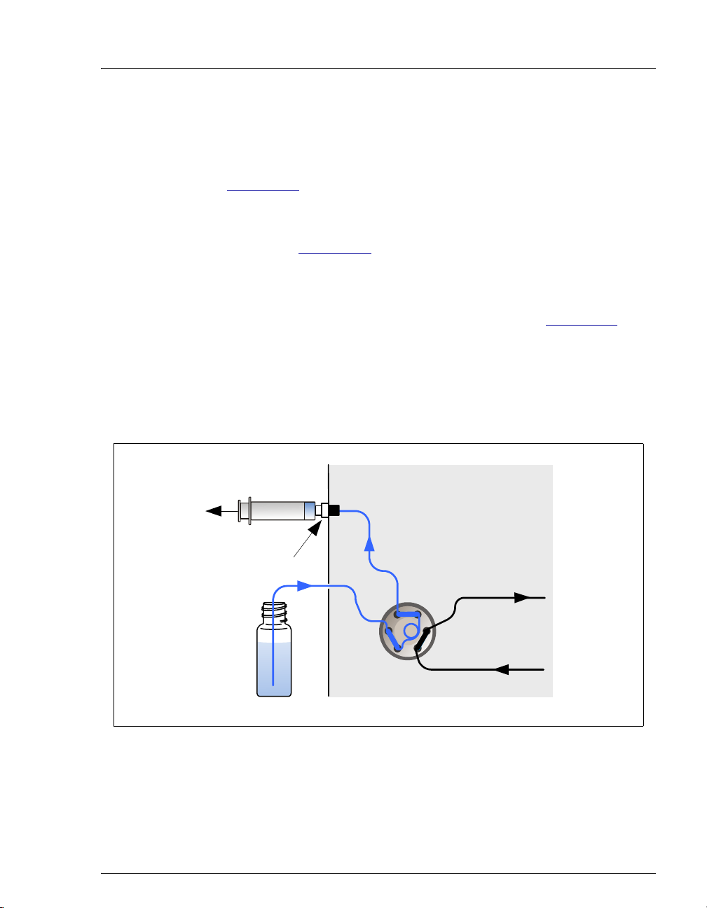
3.11.5 Loading and Injecting Samples with a Syringe
This section describes two methods for loading sample into the injection
valve sample loop with a syringe:
• Loading sample with a syringe through the sample loading port on the
front of the ICS-900 (push method)
• Loading sample with a vacuum syringe through the sample loading
port on the front of the ICS-900 (pull method)
NOTE For instructions on how to load and inject
samples with an autosampler, see Section 3.11.4
Loading Samples with a Syringe (Push Method)
1. Verify that the sample loading port on the front of the ICS-900 is
connected to sample port
Figure 3-14
).
2. Fill a syringe with a calibration standard or sample.
S (5) on the injection valve (see
.
3. Insert the syringe into the sample loading port on the front of the
ICS-900.
4. Verify that the injection valve is in the Load position. If it is not, click
the Load button on the ICS-900 Control panel (see Figure 3-11
).
5. Overfill the sample loop with five sample loop volumes. Remember
that the line from the syringe to the valve must be filled first before
the sample loop can be filled. Excess sample will exit through the
injection valve waste line.
6. Leave the syringe in the port. This prevents the sample from
siphoning out of the loop before injection.
7. Use one of the following methods to inject the sample onto the
column:
• Manually: Click the Inject button on the ICS-900 Control panel.
See Section 3.11.2
for details about manually processing samples.
• Automatically: Include the Inject command in a Chromeleon or
Chromeleon Xpress program. See the examples in Section 3.11.6
See Section 3.11.3
samples.
for details about automatically processing
.
46 Doc. 065215-02 9/09
Page 55
3 • Operation and Maintenance
Loading Samples with a Vacuum Syringe (Pull Method)
1. Verify that the sample loading port on the front of the ICS-900 is
connected to sample port
Figure 3-14
).
S (5) on the injection valve (see
2. Disconnect the waste line from port
W (6) on the injection valve and
attach a shorter line: 25 to 30 cm (10 to 12 in) of PEEK or Teflon®
tubing (see Figure 3-14
).
3. Place the free end of this line into the sample.
4. Verify that the injection valve is in the Load position. If it is not, click
the Load button on the ICS-900 Control panel (see Figure 3-11
).
5. Insert a syringe into the sample loading port on the front door and pull
out the plunger to draw the sample into the injection valve. Draw at
least five times the sample loop volume. Remember that the line from
the sample to port
W (6) on the injection valve must be filled first
before the sample loop can be filled.
Syringe
Sample
Loading Port
(on front door)
(4)(5)
L
S
C
(3)
(2)
P
Sample
W
(6)
(1)
L
Injection Valve
Figure 3-14. Loading Sample with a Vacuum Syringe (Pull Method)
Doc. 065215-02 9/09 47
Page 56

ICS-900 Operator’s Manual
6. Use one of the following methods to inject the sample onto the
column:
• Manually: click the Inject button on the ICS-900 Control panel.
See Section 3.11.2
for details about manually processing samples.
• Automatically: Include the Inject command in a Chromeleon or
Chromeleon Xpress program. See the examples in Section 3.11.6
See Section 3.11.3
for details about automatically processing
samples.
3.11.6 Example Chromeleon Commands for Loading and Injecting Samples
The following examples show commands for loading and injecting
samples using an AS, AS-DV, or AS40 autosampler.
Example AS Program Commands
0.000 Pump_ECD.Autozero ;Zero the baseline.
.
Load ;Switch the valve to Load.
Wait CycleTimeState ;Wait for cycle time (if any).
Inject ;Switch the valve to Inject.
Wait InjectState ;Wait for injection to complete.
ECD_1.AcqOn ;Start data acquisition.
14.000 ECD_1.AcqOff ;Stop data acquisition.
Example AS-DV Program Commands
Sampler.LoadPosition ;Switch the valve to Load.
DeliverSample ;Deliver sample to the valve.
0.000 Autozero ;Zero the baseline.
Wait CycleTimeState ;Wait for cycle time (if any).
Inject ;Switch the valve to Inject.
ECD_1.AcqOn ;Start data acquisition.
14.000 ECD_1.AcqOff ;Stop data acquisition.
48 Doc. 065215-02 9/09
Page 57

3 • Operation and Maintenance
Example AS40 Program Commands
-2.300 Pump_ECD_Relay_1.Closed Duration=138.00 ;Note 1
0.000 Pump_ECD.Autozero ;Note 2
ECD_1.AcqOn ;Note 3
Pump_InjectValve.InjectPosition Duration=30.00 ;Note 4
30.00 ECD_1.AcqOff ;Note 5
AS40 Program Command Notes:
1. Close the ICS-900 RELAY OUT 1, which is connected to the AS40
LOAD relay. This signals the AS40 to load the sample.
2. Zero the baseline.
3. Start data acquisition.
4. Switch the valve to Inject for 30 seconds.
5. Stop data acquisition.
3.12 Maintenance
This section describes routine maintenance procedures for the ICS-900 that users
may perform. All other maintenance procedures must be performed by Dionex
personnel.
As Needed
• Make fresh eluent.
• Regularly check the eluent bottle and refill it when needed.
• Every time you refill the eluent bottle, also empty the regenerant bottle, rinse
it, and refill it with fresh regenerant. Reset the Eluent Remaining slider on
the ICS-900 Control panel (see page 29
Doc. 065215-02 9/09 49
).
Page 58

ICS-900 Operator’s Manual
Daily
• Check the ICS-900 component mounting panel (see Figure 2-2) for leaks or
spills. Wipe up spills. Isolate and repair leaks (see Section 4.2
dried eluent or regenerant with deionized water.
• Check the waste container and empty when needed.
Weekly
• Check fluid lines for crimping or discoloration. Relocate any pinched lines.
Replace damaged lines.
• Check the back of the pump head and underneath the head for evidence of
liquid leaks. Normal friction and wear may gradually result in small liquid
leaks around the piston seal. If unchecked, these leaks can gradually
contaminate the piston housing, causing the pump to operate poorly. If leaks
occur, replace the piston seals (see Section 5.7
Annually
• Change the pump seals (see Section 5.7).
• Rebuild the injection valve (see Section 5.10).
). Rinse off any
).
• If an AS or AS-DV autosampler is installed, perform the preventive
maintenance procedure. Kits are available for this purpose: AS Preventive
Maintenance Kit (P/N 060581), AS-DV Preventive Maintenance Kit
(P/N 072678).
• If an AS40 Automated Sampler is installed, replace the sample tip and tubing.
The ASM/AS40 Sample Tip Replacement Kit (P/N 040835) contains all of
the components required to replace the sampling tip and the tubing between
the tip and the injection valve. For instructions on how to replace the sampling
tip, see the AS40 Automated Sampler Operator’s Manual (Document No.
034970). The manual is included on the Dionex Reference Library CD-ROM
(P/N 053891).
50 Doc. 065215-02 9/09
Page 59

This chapter is a guide to troubleshooting problems that may occur while
operating the ICS-900 Ion Chromatography System (ICS-900).
• Section 4.1 describes the error messages displayed in the Chromeleon or
Chromeleon Xpress Audit Trail.
• Section 4.2 through Section 4.13 describe other operating problems and how
to resolve them.
If you are unable to eliminate a problem, contact Dionex for help. In the U.S., call
Dionex Technical Support at 1-800-346-6390. Outside the U.S., call the nearest
Dionex office.
4.1 Alarms and Error Conditions
If any of the following alarm conditions occurs, an error message is displayed in
the Chromeleon or Chromeleon Xpress Audit Trail. Each error message is
preceded by an icon that identifies the seriousness of the underlying problem (see
the table below).
4 • Troubleshooting
Icon Severity Level Description
Warning A message is displayed in the Audit Trail, but the
current run is not interrupted.
Error A message is displayed in the Audit Trail and the
system attempts to correct the problem (sometimes
by using an alternative parameter). An Error never
interrupts the current analysis; however, if it occurs
during the Ready Check, the analysis will not be
started.
Abort A message is displayed in the Audit Trail and the
running batch is aborted.
Doc. 065215-02 9/09 51
Page 60

ICS-900 Operator’s Manual
The table below lists the ICS-900 error messages. For troubleshooting assistance,
refer to the page indicated in the table
Alarms and Error Conditions See
Conductivity exceeds limit.
Flow rate calibration error.
Load/inject valve error.
Module data buffer overflow. Data may have been lost.
Pump motor lost control.
Pump pressure hardware error.
Pump pressure slope calibration error.
Remaining eluent below 200 mL.
The system pressure is below the low pressure limit.
The system pressure has exceeded the high pressure limit.
Conductivity exceeds limit.
.
page 52
page 53
page 53
page 54
page 54
page 54
page 55
page 55
page 56
page 56
This message may appear at when the ICS-900 power is turned on. If the
message appears at other times, it indicates a problem.
To troubleshoot:
1. Perform the suppressor inline quick start procedure:
a. Disconnect the separator column outlet line from the suppressor
ELUENT IN port and disconnect the cell inlet line from the suppressor
ELUENT OUT port. Use a union to connect these two lines.
b. Turn on the pump flow and allow the suppressor to regenerate for
10 minutes.
c. Turn off the pump and allow the suppressor to hydrate for 20 minutes.
d. Reconnect the separator column outlet line and cell inlet line to the
suppressor ports.
2. If the high background persists:
• Prepare fresh eluent (see Section 3.4).
• Prepare fresh regenerant (see Section 3.5).
52 Doc. 065215-02 9/09
Page 61

4 • Troubleshooting
• Verify the cell calibration by pumping deionized water through the
cell (bypassing the column(s) and suppressor). The total background
should be less than 1.0
μS.
• Perform the suppressor off-line regeneration procedure.
a. Disconnect the liquid lines from the suppressor and remove the
suppressor from the ICS-900.
b. Use a syringe to push the following types and amounts of fluid
into the suppressor ports:
• AMMS® 300: Push about 3 mL of 100 mM H
ELUENT OUT port and about 5 mL of 100 mM H
REGEN IN port.
through the
2SO4
2SO4
through the
• CMMS® 300: Push about 3 mL of 200 mM NaOH through the
ELUENT OUT port and about 5 mL of 200 mM NaOH through the
REGEN IN port.
c. Allow the suppressor to sit for at least 20 minutes to fully hydrate
it.
• If the problem persists, replace the suppressor (see Section 5.12).
Flow rate calibration error.
This error occurs if you try to calibrate the flow rate when the pump is off, or
it is on, but the flow rate is not 1 mL/min.
To troubleshoot:
• Before calibrating the flow rate, be sure to press the Start Calibration
button on the Wellness panel. This will automatically start the pump and
set the flow rate to 1 mL/min. For flow rate calibration instructions, see
Section 5.1.5
.
Load/inject valve error.
If the injection valve fails to switch positions within 1 second of being
toggled, the ICS-900 Moduleware reports an error to Chromeleon or
Chromeleon Xpress and this error message is displayed.
Doc. 065215-02 9/09 53
Page 62
ICS-900 Operator’s Manual
To troubleshoot:
1. If a sequence is being executed, terminate the sequence by selecting Stop
on the Batch menu.
2. Turn off the ICS-900 power briefly and then restart.
3. Try to toggle the valve from Load to Inject by clicking the Inject button
on the ICS-900 Control panel.
4. If the problem persists, contact Dionex for assistance.
Module data buffer overflow. Data may have been lost.
Various electronics-related problems can cause this error message to be
displayed.
If this warning appears, contact Dionex for assistance. The ICS-900
electronics components cannot be serviced by the user.
Pump motor lost control.
This error indicates a problem in the pump controller electronics.
To troubleshoot:
• Contact Dionex for assistance. The ICS-900 electronics components
cannot be serviced by the user.
Pump pressure hardware error.
This error indicates a problem in the pump controller electronics.
To troubleshoot:
• Contact Dionex for assistance. The ICS-900 electronics components
cannot be serviced by the user.
54 Doc. 065215-02 9/09
Page 63
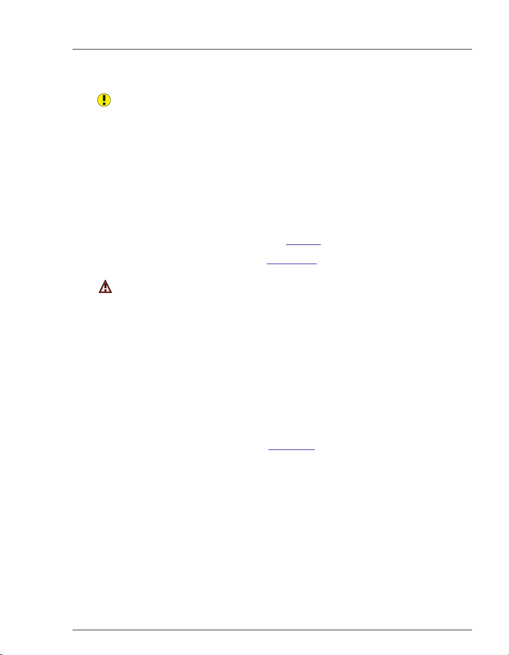
4 • Troubleshooting
Pump pressure slope calibration error.
This error occurs if you try to calibrate the pressure slope when the pressure is
less than 3 MPa (500 psi).
To troubleshoot:
• Verify that the pump is on and the flow rate is at the rate required for the
application.
• Verify that the pressure gauge is working correctly.
• Verify that the correct number and type of backpressure coils are
installed. Refer to the tables on page 63
.
• Check for liquid leaks (see Section 4.2).
Remaining eluent below 200 mL.
-or-
Remaining eluent below 100 mL.
These errors occur when the ICS-900 determines that the eluent bottle
contains less than the volume specified in the message.
To troubleshoot:
• The ICS-900 determines the eluent usage by monitoring the flow rate and
the length of time the pump is on. For the eluent level to be accurate, you
must enter the level on the ICS-900 Control panel each time the bottle is
filled. After filling the bottle, move the Eluent Remaining slider on the
ICS-900 Control panel (see Figure 3-3
the bottle.
) to indicate the volume of liquid in
Doc. 065215-02 9/09 55
Page 64

ICS-900 Operator’s Manual
The system pressure is below the low pressure limit.
If the system pressure falls below the minimum pressure limit for 0.5 second,
Chromeleon or Chromeleon Xpress stops the pump and displays this error
message. The minimum pressure limit can be set to between 0 and 33.7 MPa
(0 and 4900 psi) in the Chromeleon Server Configuration Properties dialog
box or the Chromeleon or Chromeleon Xpress program.
To troubleshoot:
1. Make sure the eluent bottle is full.
2. Check for liquid leaks (see Section 4.2
3. Prime the pump (see Section 3.6
4. Restart the pump from the ICS-900 Control panel (see Section 3.6
For additional troubleshooting information about pump priming, see
Section 4.3
The system pressure has exceeded the high pressure limit.
If the system pressure exceeds the maximum pressure limit for 0.5 second,
Chromeleon or Chromeleon Xpress stops the pump and display this error
message. The maximum pressure limit can be set to between 0.7 and
34.4 MPa (100 and 5000 psi) in the Chromeleon or Chromeleon Xpress
Server Configuration or control program.
To troubleshoot:
1. Check for blockages in the liquid lines by working your way backward
from the cell to the pump (see Figure 2-4
2. Restart the pump from the ICS-900 Control panel.
For additional troubleshooting information about system pressure, see
Section 4.7
.
.
).
).
).
for the flow schematic).
56 Doc. 065215-02 9/09
Page 65

4.2 Liquid Leaks
• Leaking fitting
Locate the source of the leak. Tighten or, if necessary, replace the liquid line
connection (see Section 5.2
Installation of Dionex Liquid Line Fittings (Document No. 031432), provided
on the Dionex Reference Library CD-ROM (P/N 053891).
• Broken liquid line
4 • Troubleshooting
). For tightening requirements, refer to the
Replace the line and fittings (see Section 5.2
).
• Blocked or improperly installed line
Make sure the lines are not crimped or otherwise blocked. Also, if the blocked
line is a waste line, make sure it is not elevated at any point after it exits the
ICS-900. If a line is blocked, replace it (see Section 5.2
).
• Loose pump check valve housing
Make sure the check valves are firmly seated in the pump head. If they are
not, tighten them carefully with an open-end wrench just until the leak stops.
• Damaged pump piston seal
1. Replace the piston seal (see Section 5.7
2. If the problem persists, replace the piston (see Section 5.8
).
).
• Pump head not tight
Carefully tighten the pump head mounting screws just until the leak stops.
DO NOT OVERTIGHTEN!
• Leaking pressure transducer
Make sure the liquid line connections into the pressure transducer are tight.
Refer to Installation of Dionex Liquid Line Fittings (Document No. 031432),
included on the Dionex Reference Library CD-ROM (P/N 053891), for
tightening requirements. Replace any damaged fittings.
Doc. 065215-02 9/09 57
Page 66

ICS-900 Operator’s Manual
• Leaking pump head waste valve
Make sure the waste valve is closed. To close the valve, turn the knob
clockwise, just until tight. DO NOT OVERTIGHTEN! Overtightening
may damage the valve and the pump head.
Inspect the pump head. If the waste valve is the source of the leak, replace the
waste valve seal (see Section 5.9
• Leaking MMS 300
Refer to the suppressor manual for troubleshooting procedures. Suppressor
manuals are included on the Dionex Reference Library CD-ROM
(P/N 053891).
• Leaking injection valve
Make sure the liquid line connections to the valve are tight. Replace any
damaged fittings. Refer to Installation of Dionex Liquid Line Fittings
(Document No. 031432) for tightening requirements. The manual is included
on the Dionex Reference Library CD-ROM (P/N 053891).
Liquid leaks from behind the valve stator may indicate a scratched rotor seal.
Rebuild the injection valve (see Section 5.10
).
).
• Leaking conductivity cell
Check the waste lines for blockage; trapped particles can plug the lines and
cause a restriction and/or leak. If necessary, clear the waste lines by reversing
the direction of flow.
Make sure the plumbing downstream from the cell is clear; a blockage may
overpressurize the cell, causing it to leak. If the problem continues, contact
Dionex for assistance.
4.3 Pump Difficult to Prime or Loses Prime
• Empty eluent bottle and/or no eluent connected
Fill the bottle. Make sure all connections are secure.
• Dirty check valve
Clean or replace the pump check valve (see Section 5.6
58 Doc. 065215-02 9/09
).
Page 67

4 • Troubleshooting
• Liquid leaks at junction between pump head and pump housing
Replace the piston seal (see Section 5.7
4.4 Pump Does Not Start
• No power (front door Power LED indicator fails to light)
Check that the power cord is plugged in.
Check the main power fuses and replace if needed (see Section 5.13
• No communication between ICS-900 and Chromeleon or Chromeleon
Xpress (
The USB cable is not connected correctly. For connection instructions, see the
ICS-900 Ion Chromatography System Installation Instructions (Document
No. 065214), provided on the Dionex Reference Library CD-ROM (P/N
053891) and in the ICS-900 Ship Kit (P/N 067768).
Link LED on rear panel fails to light)
4.5 No Flow
• Pump not primed
Prime the pump (see Section 3.6
• Broken pump piston
).
).
).
Replace the piston (see Section 5.8
).
4.6 Erratic Flow/Pressure Reading
• Pump needs priming
Prime the pump (see Section 3.6
• Damaged piston seal
Replace the piston seal (see Section 5.7
• Dirty pump check valve
Clean or replace the check valve (see Section 5.6
Doc. 065215-02 9/09 59
).
).
).
Page 68

ICS-900 Operator’s Manual
4.7 Excessive System Backpressure
• Restriction in system plumbing
Check all liquid lines for crimping or blockage. Make sure the ferrule fittings
are not overtightened onto tubing. Refer to Installation of Dionex Liquid Line
Fittings (Document No. 031432) for details. The manual is included on the
Dionex Reference Library CD-ROM (P/N 053891).
• Plugged or damaged fitting
Isolate the faulty fitting by loosening fittings, one by one, until the pressure
returns to normal. Repair or replace the fitting (see Section 5.2
• Flow rate through columns too high
Check the pump flow rate.
• Clogged column bed supports
Refer to the instructions in the column manual for troubleshooting guidance.
Column manuals are included on the Dionex Reference Library CD-ROM
(P/N 053891).
).
• Contaminated columns
Clean the columns as instructed in the column manual. Column manuals are
included on the Dionex Reference Library CD-ROM (P/N 053891).
• Plugged Injection valve passages
Rebuild the injection valve (see Section 5.10
4.8 Peak “Ghosting”
Ghosting is the appearance of extraneous peaks in a chromatogram. These may be
late-eluting peaks from a previous injection or they may result from a
contaminated, malfunctioning, or incorrectly installed injection valve. These
peaks may co-elute with peaks of interest, resulting in nonreproducible peak
heights/areas.
• Insufficient time between sample injections
Wait until the previous sample has been completely eluted before making
another injection.
).
60 Doc. 065215-02 9/09
Page 69

4 • Troubleshooting
• Insufficient flush between samples
Flush the sample loop with at least 10 loop volumes of deionized water or
sample between sample injections.
• Incorrect or contaminated standards
Remake standards.
• Incorrect or contaminated eluent
Remake the eluent (see Section 3.4
).
• Malfunctioning injection valve
Contact Dionex for assistance.
4.9 Nonreproducible Peak Height or Retention Time
• Column overloading
Dilute the sample (see Section 3.10.3
).
• Liquid leaks
Locate and eliminate the leaks (see Section 4.2
).
• Incomplete or imprecise filling of the sample loop
1. Fill the sample loop until excess sample exits the waste line.
2. Inspect the 1 cc syringe (P/N 016388) and replace if damaged.
• Pump not primed properly
Prime the pump (see Section 3.6
).
4.10 Abnormal Retention Time or Selectivity
• Contaminated or incorrect eluent
Remake the eluent, using concentrated eluent and ASTM Type I (18megohm) filtered and deionized water (see Section 3.4
).
• Contaminated or degraded sample
Take appropriate precautions when preparing and storing samples to prevent
contamination and degradation (see Section 3.10
Doc. 065215-02 9/09 61
).
Page 70

ICS-900 Operator’s Manual
• Contaminated column
1. Clean the column as instructed in the column manual. Column manuals
are included on the Dionex Reference Library CD-ROM (P/N 053891).
2. If cleaning is unsuccessful, replace the column.
4.11 No Detector Response
• Cell not properly installed
Check that the cell is plugged into the component mounting panel and the cell
housing is screwed down until the bottom of the housing is flush against the
sheet metal panel (see Figure 2-2
• No flow from pump
and Figure 2-10).
Several conditions may cause this condition; see Section 4.4
for details.
• Cell electronics malfunctioning
Use the Wellness panel to test the electronics with a dummy cell (see
Section 5.1
reading with the dummy cell is outside the tolerance range, the electronics are
malfunctioning. Contact Dionex for assistance.
and the Chromeleon Help for instructions). If the conductivity
4.12 High Detector Output
• Background not suppressed by suppressor
If
Conductivity exceeds limit is displayed in the Chromeleon or Chromeleon
Xpress Audit Trail, follow the instructions in Section 4.1
troubleshooting guidance, refer to the suppressor manual. Suppressor manuals
are included on the Dionex Reference Library CD-ROM (P/N 053891).
• Sample concentration too high
Dilute the sample (see Section 3.10.3
• Wrong eluent or regenerant
Check that you are using the correct eluent and regenerant for your system
(see Section 3.4
).
and Section 4.5
. For additional
).
62 Doc. 065215-02 9/09
Page 71

• Cell out of calibration
4 • Troubleshooting
Recalibrate the cell from the Wellness panel (see Section 5.1
4.13 Baseline Noise or Drift
• Flow system leak; erratic baseline
Check all fittings and liquid lines for leaks. Tighten or, if necessary, replace
all liquid line connections. Refer to Installation of Dionex Liquid Line Fittings
(Document No. 031432) for tightening requirements. The manual is included
on the Dionex Reference Library CD-ROM (P/N 053891).
• Trapped gases
Release any trapped gases in the cell by loosening the lines to and from the
cell and then retightening them. Also loosen and retighten the fittings to and
from the MMS eluent ports.
• Pump not properly primed
Prime the pump (see Section 3.6
• Contaminated or incorrect eluent and/or regenerant
Remake the eluent and regenerant (see Section 3.4
• Rapid changes in ambient temperature
).
).
).
If the ambient temperature does not meet the specification of 10 to 35 °C (50
to 95 °F), verify that air conditioning and heating vents are directed away
from the ICS-900 and the ICS-900 front door is closed.
• Insufficient conductivity cell backpressure
Verify that the correct backpressure coils are installed:
Standard bore systems: Use one or two black backpressure coils
(P/N 045877) supplied in the ICS-900 Ship Kit (P/N 067768).
Flow Rate Number of Coils
1.5 to 3.0 mL/min
0.5 to 1.5 mL/min
Doc. 065215-02 9/09 63
1 (black)
2 (black)
Page 72

ICS-900 Operator’s Manual
Microbore systems: Use one or two red backpressure coils (P/N 045878)
supplied in the microbore tubing kit (P/N 052324).
Flow Rate Number of Coils
0.3 to 0.5 mL/min
Less than 0.3 mL/min
Install the tubing between the cell outlet and the regenerant bottle inlet. For
connection instructions, see the ICS-900 Ion Chromatography System
Installation Instructions (Document No. 065214), provided on the Dionex
Reference Library CD-ROM (P/N 053891) and in the ICS-900 Ship Kit
(P/N 067768).
• Insufficient system equilibration following changes to operating
parameters; especially apparent when operating at high sensitivities
Allow a longer system equilibration time (up to 3 hours) before starting to
inject samples.
• Incorrect suppressor operating conditions
Refer to the suppressor manual for troubleshooting information. Suppressor
manuals are included on the Dionex Reference Library CD-ROM
(P/N 053891).
1 (red)
2 (red)
• Cell above or below temperature
Contact Dionex for assistance.
• Damaged piston seal
Replace the piston seal (see Section 5.7
).
• DCR backpressure tubing not installed or incorrectly installed
Install the tubing on the end of the suppressor waste line. For connection
instructions, see the ICS-900 Ion Chromatography System Installation
Instructions (Document No. 065214), provided on the Dionex Reference
Library CD-ROM (P/N 053891) and in the ICS-900 Ship Kit (P/N 067768).
64 Doc. 065215-02 9/09
Page 73

5•Service
This chapter describes ICS-900 Ion Chromatography System (ICS-900) service
and repair procedures that users may perform. Procedures not included here,
including electronics-related repair procedures, must be performed by Dionex
personnel. For assistance, contact Dionex Technical Support. In the U.S., call 1800-346-6390. Outside the U.S., call the nearest Dionex office.
Before replacing any part, refer to the troubleshooting information in Chapter 4
correctly identify the cause of the problem.
Substituting non-Dionex parts may impair system performance,
thereby voiding the product warranty. Refer to the warranty statement
in the Dionex Terms and Conditions for more information.
5.1 Diagnostics and Calibrations
The Wellness panel (see Figure 5-2) provides controls for performing diagnostic
and calibration functions. This section provides an overview of Wellness panel
features. For calibration procedures, see the following sections:
• “Calibrating the Pressure Transducer” (Section 5.1.3)
• “Calibrating the Cell” (Section 5.1.4)
• “Calibrating the Flow Rate” (see Section 5.1.5)
5.1.1 Opening the Wellness Panel
1. In the Chromeleon Browser, expand the Dionex
Templates\Panels\Wellness folder.
to
Doc. 065215-02 9/09 65
Page 74
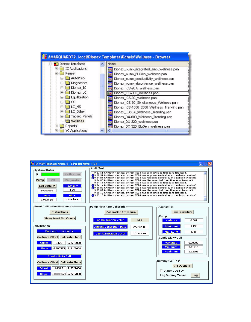
ICS-900 Operator’s Manual
2. Double-click Dionex_ICS-900_wellness.pan (see Figure 5-2).
Figure 5-1. Opening the Wellness Panel
The Wellness panel opens (see Figure 5-2
Figure 5-2. ICS-900 Wellness Panel
).
66 Doc. 065215-02 9/09
Page 75

5•Service
3. If the controls on the Wellness panel are disabled, select Connect to
timebase on the Control menu and select the ICS-900 timebase.
5.1.2 Wellness Panel Features
The Wellness panel provides the following features:
System Status • The check box indicates whether the ICS-900 is connected to
Chromeleon or Chromeleon Xpress. When there is no
connection, the check box is clear and the remaining controls
on the Wellness panel are disabled.
• Click the Pump button to turn the pump on and off.
• Click the Log Serial # button to record the ICS-900 serial
number in the Audit Trail.
• The Calibration or Diagnostic box is green while a
calibration or diagnostic procedure is running.
• The current total system Pressure, pump Flow rate, and
electrochemical detector (ECD) conductivity are displayed.
Audit Trail
Reset
Calibration
Parameters
• The Audit Trail displays an account of every event that occurs
during ICS-900 operation. This includes errors, status
messages, operational events, etc.
• Click the View/Reset Cal Values button to open a window
that shows the current calibration values, the previous values,
and the factory-set values. You can reset the current
calibration values to the previous or factory-set values from
the window.
Doc. 065215-02 9/09 67
Page 76

ICS-900 Operator’s Manual
Calibration
Diagnostic
• Pressure Transducer
• Use the Calibrate Offset and Calibrate Slope buttons
when performing the pressure transducer calibration
procedure (see Section 5.1.3
).
• The Offset and Slope values and the date of the last
calibration are displayed.
• Conductivity Cell
• Use the Calibrate Offset and Calibrate Slope buttons
when performing the cell calibration procedure (see
Section 5.1.4
).
• The Offset and Slope values and the date of the last
calibration are displayed.
• Pump Flow Rate Calibration
• Click Calibration Procedure to perform the calibration
(see Section 5.1.5
).
• Click Log to record the calibration value in the Audit
Trail.
• The Pump and Conductivity Cell Variance values are a
measure of the noise of the respective channels. The values of
these measurements will vary with differing eluents, pump
seal age and wear, background conductivity, and so on. When
values (obtained under the same conditions) are compared
they can be used as a relative measure of the performance of
the system.
• The Variance, Minimum, and Maximum readings for the
last time the Pump and Conductivity Cell diagnostic tests
were run are displayed.
Dummy Cell
Test
• The Dummy Cell Test connects a fixed resistance in place of
the conductivity cell. A measured value outside the typical
range of the test indicates a failure in the detector electronics.
• Click Log to perform the test and record the value in the
Audit Trail. Clicking Log enables the dummy cell, logs the
value, and then disables the dummy cell.
• The Dummy Cell On check box enables and disables the
dummy cell.
68 Doc. 065215-02 9/09
Page 77
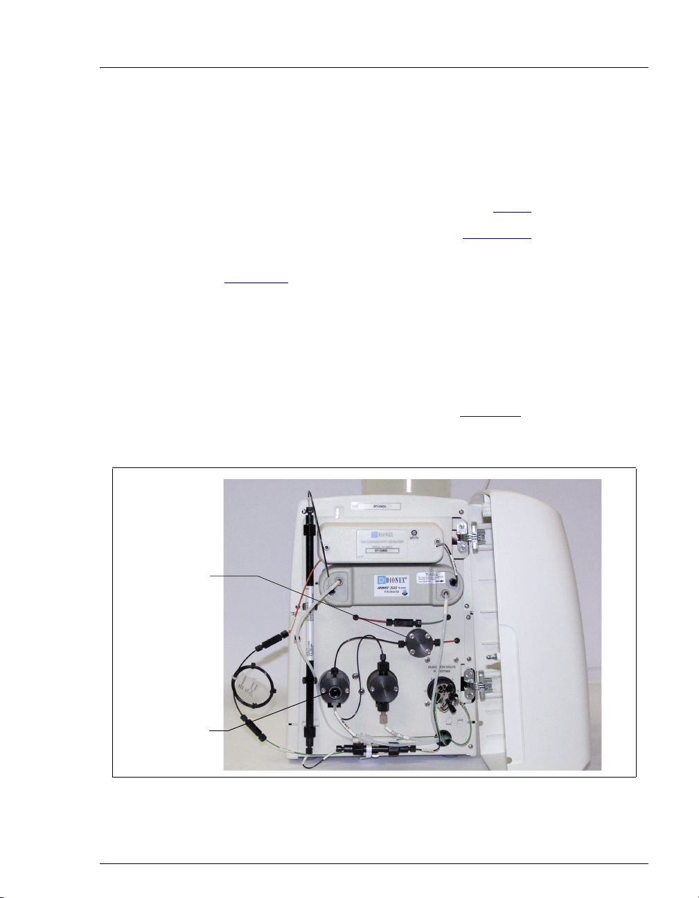
5.1.3 Calibrating the Pressure Transducer
1. Toggle the injection valve position a few times by clicking the Load
and Inject buttons on the ICS-900 Control panel. This removes any
air or contaminant buildup in the injection valve loop.
5•Service
Pressure
Transducer
2. Wait about 10 minutes and then continue to Step 3
3. Open the ICS-900 Wellness panel (see Section 5.1
.
).
4. Under Pressure Transducer, click the Calibrate Offset button (see
Figure 5-2
). A panel with instructions and command buttons will
open.
5. Follow the instructions on the panel to complete the transducer offset
calibration procedure. The new offset is determined and stored as the
current value.
NOTE To open the waste valve on the front of the
secondary pump head (see Figure 5-3
knob one-half turn counterclockwise.
), turn the
Waste Valve
Figure 5-3. ICS-900 Interior Components
Doc. 065215-02 9/09 69
Page 78
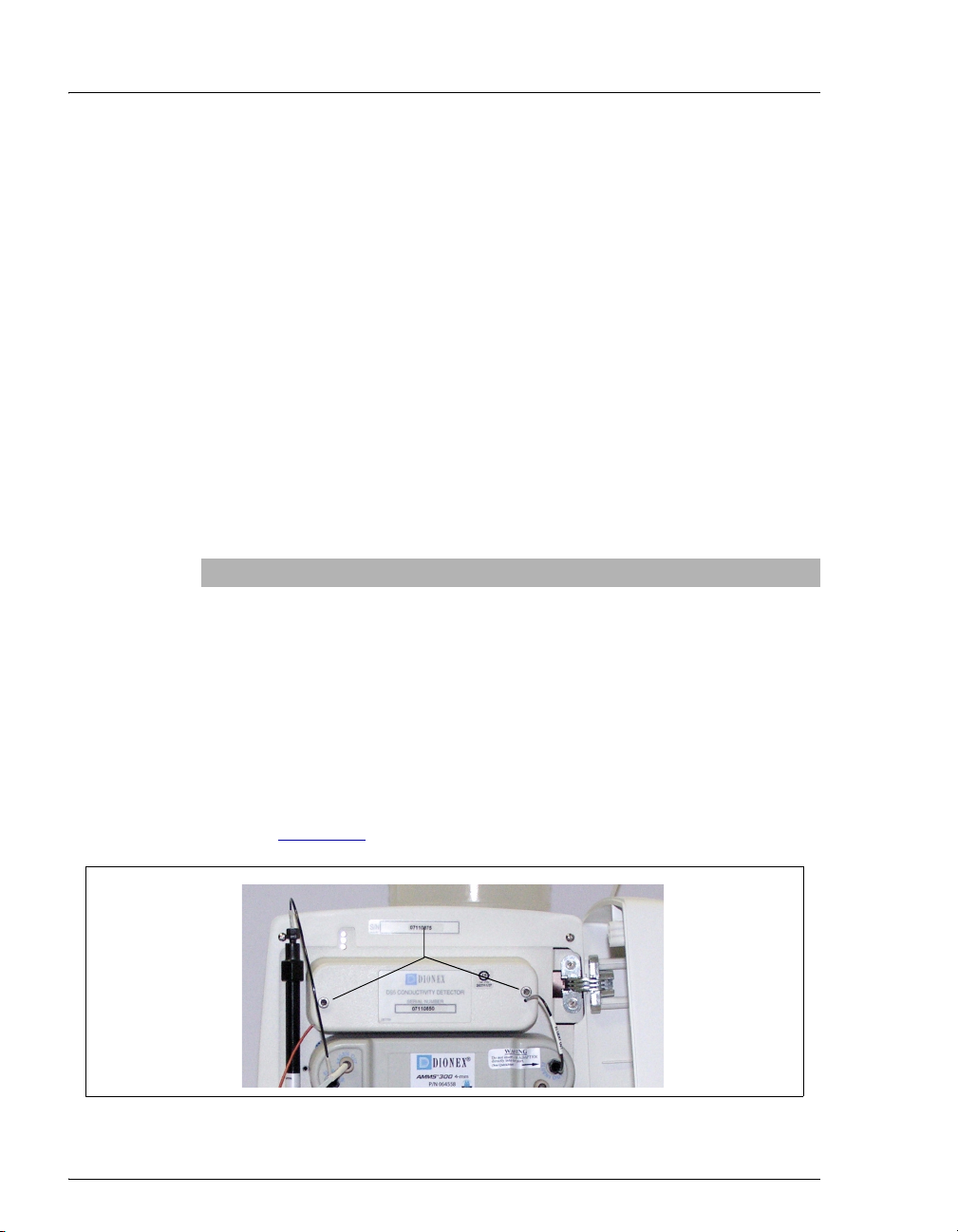
ICS-900 Operator’s Manual
6. Close the waste valve.
7. Under Pressure Transducer, click the Calibrate Slope
panel with instructions and command buttons will open.
8. Follow the instructions on the panel to complete the transducer slope
calibration procedure. The new slope is determined and stored as the
current value.
9. Turn off the pump.
10. Disconnect the pressure gauge and backpressure coil.
11. Reconnect the pressure transducer to the pump.
5.1.4 Calibrating the Cell
Calibrate the cell every 6 months or after installing a new conductivity
cell.
Items Needed Description
1.00 mM KCl solution Prepare by dissolving 0.0746 g of reagent-
Backpressure tubing to provide
at least 7 MPa (1000 psi)
button. A
grade KCl in one liter of ASTM Type I
(18 megohm-cm) filtered and deionized
(DI) water (use a volumetric flask).
Use 0.076-mm (0.003-in) ID yellow PEEK
tubing (P/N 049715).
1. Use an Allen wrench to remove the two screws securing the
conductivity cell housing to the ICS-900 component mounting panel
(see Figure 5-4
Figure 5-4. ICS-900 Interior Components: Removing the Conductivity Cell Housing
70 Doc. 065215-02 9/09
). Save the screws.
Remove Screws
Page 79

5•Service
2. Pull the cell housing straight out from the component mounting panel
to unplug the cell from its electronics. Let the cell housing hang by
the tubing.
3. Open the ICS-900 Wellness panel (see Section 5.1
).
4. Under Conductivity Cell, click the Calibrate Offset button (see
Figure 5-2
). A panel with instructions and command buttons will
open.
5. Follow the instructions on the panel to complete the conductivity cell
offset calibration procedure. The new offset is determined and stored
as the current value.
NOTE To reinstall the cell, on the mounting panel,
align the 9-pin connectors on the cell housing
with the component mounting panel and plug
the cell back into the electronics. Replace the
mounting screws (removed in Step 1
tighten.
) and
6. Under Conductivity Cell, click the Calibrate Slope button. A panel
with instructions and command buttons will open.
7. Follow the instructions on the panel to complete the conductivity cell
slope calibration procedure. The new slope is determined and stored
as the current value.
NOTE After calibration, the conductivity reading
should be 147.00 ± 2 μS/cm. If this is not the
case, call Dionex for assistance.
8. Flush the KCl solution from the system by pumping DI water through
the cell. When the conductivity drops to near zero, stop the pump
flow.
9. Reconnect the pump to the injection valve and reconnect the line
from the suppressor to the cell inlet.
Doc. 065215-02 9/09 71
Page 80

ICS-900 Operator’s Manual
5.1.5 Calibrating the Flow Rate
Calibrate the flow rate if the Operational Qualification or Performance
Qualification flow rate accuracy and precision test fails.
Items needed:
• 0.076-mm (0.003-in) ID yellow PEEK tubing (P/N 049715) to create
14 ± 2 MPa (2000 ± 300 psi) of backpressure (if needed)
• High purity ASTM Type I (18 megohm-cm) filtered and deionized
water
• Balance capable of weighing more than 10 g with 0.001 g readability
• Tared beaker
To calibrate:
1. Open the ICS-900 Wellness panel (see Section 5.1).
2. Under Pump Flow Rate Calibration, click Calibration Procedure.
A panel with instructions and command buttons will open.
3. Follow the instructions on the panel to complete the conductivity cell
slope calibration procedure. The new slope is determined and stored
as the current value.
NOTE Enter the weight of the collected water (in
grams, to the nearest milligram).
4. Click Log to record the new calibration value in the Audit Trail. This
value is stored as the current value.
72 Doc. 065215-02 9/09
Page 81

5.2 Replacing Tubing and Fittings
The ICS-900 is plumbed with the tubing and tubing assemblies listed below.
Tubing Size and Type Used For
0.125-mm (0.005-in) ID PEEK, red
(P/N 044221)
0.25-mm (0.010-in) ID PEEK, black
(P/N 042690)
0.50-mm (0.020-in) ID Tefzel®, light
blue (P/N 035519)
0.75-mm (0.030-in) ID PEEK, green
(P/N 044777)
1.6-mm (0.062-in) ID Teflon®,
natural (P/N 014157)
Microbore tubing kit (P/N 052324) Tubing for exchanging black 0.25-mm
Connection from pump pulse damper to
pressure transducer
Connections between all other system
components
Connection from injection port on door to
injection valve
Connections from injection valve to waste,
injection valve to pump pulse damper, and
cell to regenerant bottle
Connections from suppressor
to regenerant bottle,
pump to eluent bottle, and pump to waste
(0.010-in) ID PEEK lines with red 0.125-mm
(0.005-in) ID lines (to reduce delay volumes).
5•Service
Regen In port
Regen Out to waste,
• 10-32 fittings (P/N 062980) and ferrules (P/N 043276) are used for most
tubing connections. For tightening requirements, refer to Installation of
Dionex Liquid Line Fittings (Document No. 031432). The manual is included
on the Dionex Reference Library CD-ROM (P/N 053891).
• 1/8-in fittings (P/N 052267) and ferrules (P/N 048949) are used for
connections to the MMS 300 regen ports and the eluent and regenerant
bottles.
• 1/16-in fittings (P/N 052230) and ferrules (P/N 052231) are used for
connections from the front door injection port to the injection valve.
Doc. 065215-02 9/09 73
Page 82

ICS-900 Operator’s Manual
5.3 Isolating a Restriction in the Liquid Plumbing
A restriction in the liquid plumbing will cause excessive system backpressure.
1. Begin pumping eluent through the system (including the columns).
2. Follow the ICS-900 flow schematic (see Figure 2-4
through the system, beginning at the cell exit. One at a time, loosen each
fitting and observe the pressure. The connection at which the pressure drops
abnormally indicates the point of restriction.
If the restriction has caused such high pressure that the system cannot be
operated, you must work forward through the flow schematic, adding parts
one at a time until an abnormal pressure increase (and hence, the restriction) is
found.
3. If the restriction is in the tubing or fitting, remove the restriction by back
flushing or by replacing the tubing or fitting.
) and work backward
74 Doc. 065215-02 9/09
Page 83

To pump inlet
5•Service
From cell outlet
Backpressure Coil
(1 or 2, depending on
flow rate)
Conductivity Cell
(in DS5 Detection Stabilizer)
Regen Out Eluent Out
Eluent In
Pulse Damper
Secondary
Pump
Heads
To Waste
MMS 300
Primary
Regen In
Transducer
Eluent
To cell inlet
To MMS
Regen In
Pressure
LP
CW
L
S
Injection
Valve
To Waste
Regenerant
Eluent in
from pulse
damper
Sample in
Figure 5-5. ICS-900 Flow Schematic
Doc. 065215-02 9/09 75
Page 84

ICS-900 Operator’s Manual
5.4 Cleaning Eluent Bottles
Before preparing new eluent, all eluent bottles should be rinsed thoroughly (inside
and out) with ASTM Type I (18 megohm-cm) filtered and deionized water. If a
bottle still appears dirty, or has a slimy film on the inside, clean it as instructed
below.
1. Dispose of any remaining chemicals according to municipal regulations.
2. Rinse the bottle (inside and out) with ASTM Type I (18 megohm-cm) filtered
and deionized water.
3. Rinse the inside of the bottle with isopropyl alcohol or methanol.
4. If algae or bacteria have left a slimy film on the bottle, use an algicide or
disinfectant (dilute hydrogen peroxide, etc.).
5. Rinse cleaning chemicals out of the bottle with ASTM Type I (18 megohmcm) filtered and deionized water.
6. Dry the bottle with clean, particulate-free air.
5.5 Changing the Sample Loop
A 10 μL PEEK sample loop (P/N 042949) is installed on the injection valve at the
factory. Unless you are using a 2 mm column, replace the sample loop with
another 10 μL PEEK sample loop. If you are using a 2 mm column, refer to the
column manual for the size of loop required. Column manuals are included on the
Dionex Reference Library CD-ROM (P/N 053891)
1. Turn off the pump from
the ICS-900 Control
panel.
2. Open the ICS-900 front
door.
3. Disconnect the sample
loop from ports
the injection valve (see
Figure 5-6
L and L on
).
Figure 5-6. ICS-900 Injection Valve
Sample Loop
76 Doc. 065215-02 9/09
Page 85

4. Install the new sample loop between the two ports.
5. Make sure the loop is tightly coiled, so that the door can close securely.
6. Turn on the pump from the ICS-900 Control panel.
7. Check for leaking fittings and tighten if required.
8. Close the door.
5.6 Cleaning and Replacing Pump Check Valves
A dirty check valve causes erratic flow rates and pressures. In addition, it may
cause the pump to lose prime and/or be difficult to reprime. If possible, replace
dirty check valves. If new check valves are not available, follow the instructions
for cleaning.
To replace the check valves:
1. Turn off the ICS-900 power switch and disconnect the power cord.
2. To prevent contamination of pump parts, put on a pair of powder-free gloves
before disassembling the pump head.
5•Service
3. Disconnect the tube fittings from the inlet and outlet check valve assemblies
on the primary pump head (see Figure 5-7
4. Use a 1/2-inch wrench to loosen both check valve assemblies. Remove the
check valve assemblies from the pump head.
).
Doc. 065215-02 9/09 77
Page 86

ICS-900 Operator’s Manual
Outlet Check
Valve
Secondary
Pump Head
Figure 5-7. Pump Heads
NOTE The inlet check valve assembly housing has a 1/4-28 port.
The outlet check valve assembly housing has a 10-32 port.
5. Inspect the new inlet check valve
assembly (P/N 045722) to verify that the
double-hole end of the cartridge is
visible (see Figure 5-8
).
Primary
Pump Head
Inlet Check
Valve
Inlet Check Valve Outlet Check Valve
1/4-28 Port
10-32 Port
If the double-hole end is not visible,
remove the cartridge from the housing
and install it correctly.
Double-hole
Single-hole
6. Inspect the new outlet check valve
assembly (P/N 045721) to verify that the
Flow
single-hole end of the cartridge is visible.
If the single-hole end is not visible,
remove the cartridge from the housing
and install it correctly.
78 Doc. 065215-02 9/09
Flow
Figure 5-8. Check Valve Assemblies
Page 87

5•Service
NOTE The pump will not operate properly unless the cartridge
is installed in the housing in the correct orientation.
Liquid flows through the check valve in the large single
hole and out the small double holes.
7. Install the inlet check valve assembly on the bottom of the primary pump
head. Install the outlet check valve assembly on the top of the head. Tighten
the check valves fingertight, and then use a wrench to tighten an additional
one-quarter to one-half turn.
Overtightening may damage the pump head and check valve housing
and crush the check valve seats.
8. Reconnect the liquid lines and the power cord. Turn on the ICS-900 main
power.
9. Prime the pump (see Section 3.6
).
10. When the ICS-900 is at operating pressure, check for leaks from the check
valves. Tighten a check valve a little more only if it leaks.
To clean the check valves:
1. Follow Step 1 through Step 4 in the check valve replacement procedure to
remove the check valve cartridges from the valve housings.
2. Place the check valve housings and cartridges in a beaker with methanol.
Sonicate or agitate the parts for several minutes.
3. Rinse each check valve housing and cartridge thoroughly with filtered
deionized water.
4. Follow Step 5
through Step 10 in the check valve replacement procedure to
reinstall the check valves.
Doc. 065215-02 9/09 79
Page 88

ICS-900 Operator’s Manual
5.7 Replacing a Pump Piston Seal and Backup Seal
A damaged seal allows leakage past the piston, as well as leakage from the piston
seal wash housing. The pump may be difficult to prime, flow rates may be
unstable, and there may be baseline noise.
Preparation:
1. Rinse the pump flow path with deionized water. Direct the flow to waste by
opening the waste valve on the secondary pump head (see Figure 5-7
open the valve, turn the knob one-half turn counterclockwise.
2. After rinsing, close the waste valve.
3. To prevent contamination of pump parts, put on a pair of rubber gloves before
disassembling the pump head.
To remove the head and piston:
1. Turn off the power switch and disconnect the power cord.
2. Disconnect all tubing connections to the pump head.
). To
3. Using a 7/64-in hex key (P/N 068227), loosen the two screws on the pump
head with the defective seal. Remove the screws, and then carefully remove
the head and place it on a clean surface.
4. Slowly pull the head and allow it to separate from the housing. Carefully
disengage the head from the piston by pulling the head straight off and away
from its mounting studs.
Lateral motion while disengaging the pump head from the piston may
break the piston.
Un mouvement latéral pendant la séparation de la tête et du piston
peut casser le piston.
Vermeiden Sie Seitwärtsbewegungen, wenn Sie den Pumpenkopg
vom Kolben lösen. Andernfalls kann der Kolben brechen.
5. Place the head (front end down) on a clean work surface
6. The piston does not come off as part of the pump head assembly because it is
captured by a magnetic retention system. After removing the pump head, hold
80 Doc. 065215-02 9/09
Page 89

5•Service
(
)
(
)
S
the shaft of the piston (near the base), tilt the piston slightly, and pull the
piston away from the pump.
Refer to Figure 5-9
pump head.
(P/N 014895)
Spacer with Drain
(P/N 067705)
Backup Piston Seal
(P/N 063382)
or Figure 5-10 when disassembling and reassembling the
Outlet Check
Valve Assembly
(P/N 045721)
Piston Seal
(P/N 055870)
O-Ring
Primary Pump Head
(P/N 067702)
Inlet Check
Valve Assembly
(P/N 045722)
Seal Holder
Piston
P/N 052840
Figure 5-9. Primary Pump Head
(P/N 067706)
Piston Seal
(P/N 055870)
(P/N 014895)
Spacer with Drain
(P/N 067705)
Backup Piston Seal
(P/N 063382)
Piston
P/N 052840
O-Ring
Seal Holder
(P/N 067706)
(P/N 063382)
eal
Prime Valve
(P/N 063968)
Secondary Pump Head
(P/N 067704)
Figure 5-10. Secondary Pump Head
Doc. 065215-02 9/09 81
Page 90
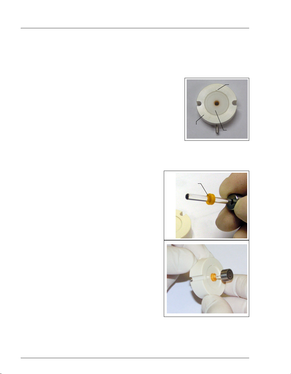
ICS-900 Operator’s Manual
To install the new backup piston seal:
1. Lift the spacer off the pump head.
2. To remove the seal holder from the spacer, use one of the following methods:
• With the seal holder facing up, cup the spacer
in your hand and blow clean laboratory air at
the spacer to dislodge the seal holder.
• Insert a thin object or pointed tool into the
small notch on the spacer and carefully pry out
the seal holder. Be careful not to scratch the
spacer.
3. To remove the backup piston seal from the spacer,
insert a thin object (for example, the straightened end of a paper clip) and
carefully pry out the backup piston seal. Be careful not to scratch the
spacer.
4. To install the new backup piston seal:
Grooved side
a. Hold the new backup piston seal
(P/N 063382) with the grooved side
facing down, and insert the shaft of the
piston through the seal.
b. Insert the piston into the center hole in
the spacer.
c. Push the piston into the spacer until
the top of the piston is flush with the
spacer. A clicking sound indicates that
the seal is correctly seated.
Spacer
of backup
piston seal
Notch
Seal
Holder
82 Doc. 065215-02 9/09
Page 91
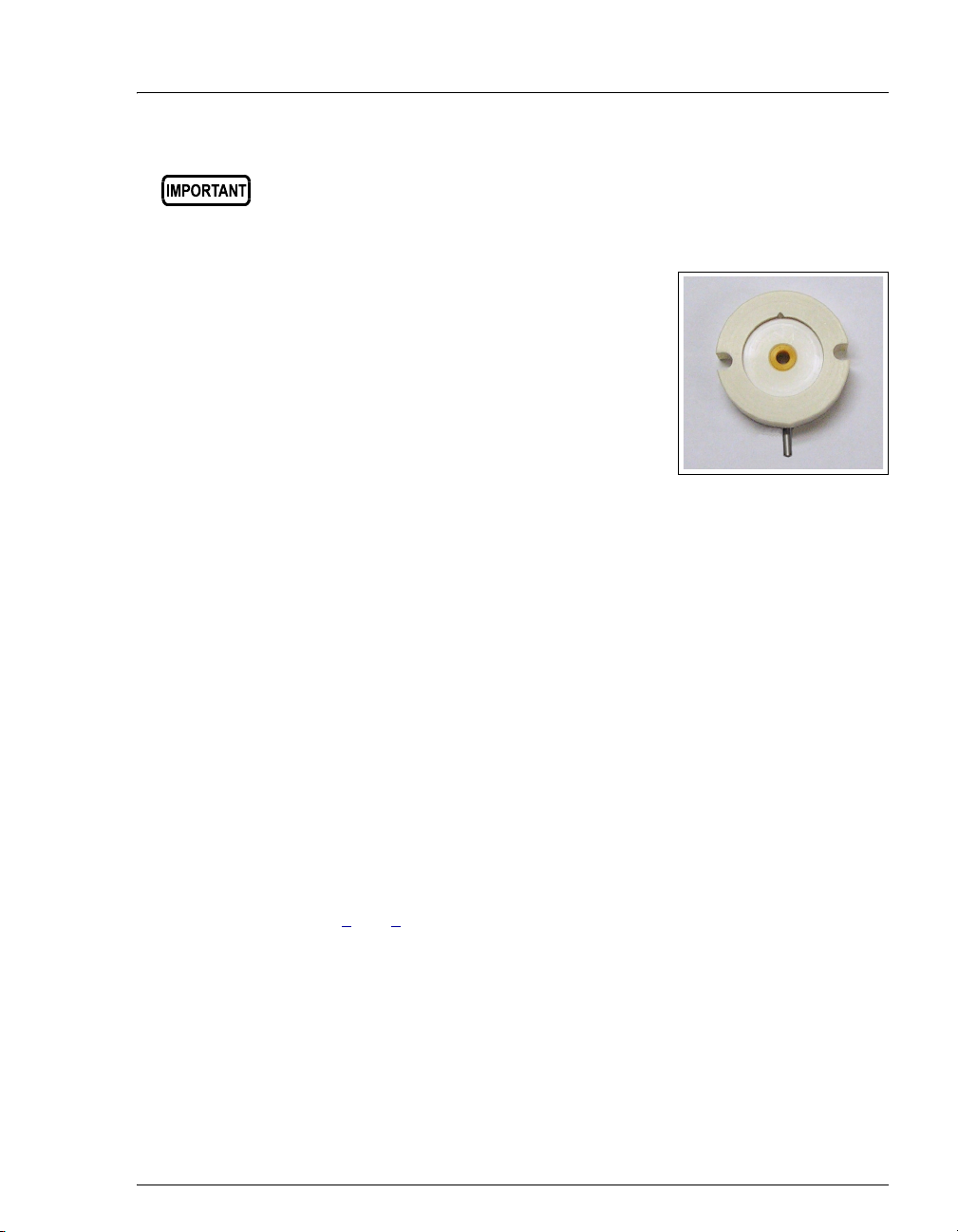
5•Service
The piston backup piston seal is made of soft plastic. Do not press on
the seal with anything hard or sharp, including your fingernail. If the
seal is nicked or gouged, it will not seal properly and may result in
leaks.
d. Pull out the piston. The top of the seal should
be flush with the surface of the spacer.
e. Press the seal holder onto the spacer.
To remove the old piston seal from the head:
1. Fill the head cavity with deionized water by injecting the liquid through the
piston opening.
2. Reinsert the piston approximately 3 mm (0.125 inch) into the seal.
3. If this is the primary pump head, install a 10-32 fitting plug (P/N 042772) on
the outlet check valve. Tighten the plug.
4. If this is the secondary pump head, install a 10-32 fitting plug (P/N 042772)
in both the inlet and outlet ports. Tighten the plugs.
5. Push the piston into the head. (This should hydraulically unseat the seal from
the head.) Remove the piston and pull off the seal.
NOTE If the piston seal is not removed, make sure the 10-32
fitting plug(s) are tight and add more water. Make sure
the head contains no air bubbles, and then repeat Steps
2
and 5.
6. Remove the 10-32 fitting plug(s).
Doc. 065215-02 9/09 83
Page 92

ICS-900 Operator’s Manual
To install the new piston seal:
1. If this is the secondary pump head, open the waste valve knob by turning the
knob one-half turn counterclockwise.
2. Lubricate the seal and the pump head
opening with a small amount of isopropyl
alcohol to facilitate insertion.
3. Push the piston through the spacer and
then through the new piston seal.
4. Insert the piston and seal into the pump
head.
Piston Seal
Piston
Spacer
5. To seat the seal, push down on the spacer
until it is flush with the head. A clicking
sound indicates that the seal is correctly
seated.
84 Doc. 065215-02 9/09
Page 93
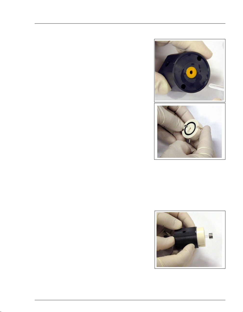
6. Remove the spacer and piston and verify
that the seal is flush with the surface of the
pump head.
7. Verify that the O-ring is installed in the
spacer.
5•Service
To reinstall the head and piston:
Dionex recommends reinstalling the head and piston as a single assembly, so that
the piston centers itself onto the magnetic follower.
1. Hold the assembled spacer and guide with the drain tube aligned vertically
and press the spacer into the head until it is flush with the indented surface of
the head.
2. Insert the piston so that about 1/4 inch of
the shaft is exposed. This ensures that the
magnet in the follower picks up the piston.
(The follower is the cylinder that holds the
piston in place as it moves in and out of the
pump head assembly.)
3. Reinstall the head and piston assembly;
tighten the screws evenly.
Doc. 065215-02 9/09 85
Page 94
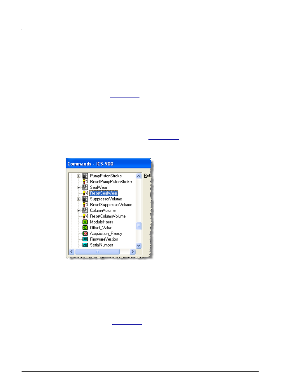
ICS-900 Operator’s Manual
To complete the procedure:
1. Reconnect all liquid lines to the pump head.
2. Close the waste valve knob.
3. Turn on the ICS-900 power switch.
4. Prime the pump (see Section 3.6
5. Reset the seal wear counter in Chromeleon or Chromeleon Xpress:
a. Press F8 to open the Commands dialog box.
b. Expand the list of commands under Pump_ECD and scroll to the
ResetSealWear command (see Figure 5-11
c. Select the command and click Execute.
Figure 5-11. Resetting the Seal Wear Counter
).
).
5.8 Replacing a Pump Piston
Continued leaking of the piston seal after installation of a new seal (assuming the
pump head is tight) indicates a dirty, scratched, or broken piston.
Follow the instructions in Section 5.7
piston seal (P/N 055870). Always replace the piston seal when replacing a piston.
After replacing the piston and seal, reset the seal wear and pump piston stroke
counters.
86 Doc. 065215-02 9/09
to install a new piston (P/N 052840) and
Page 95
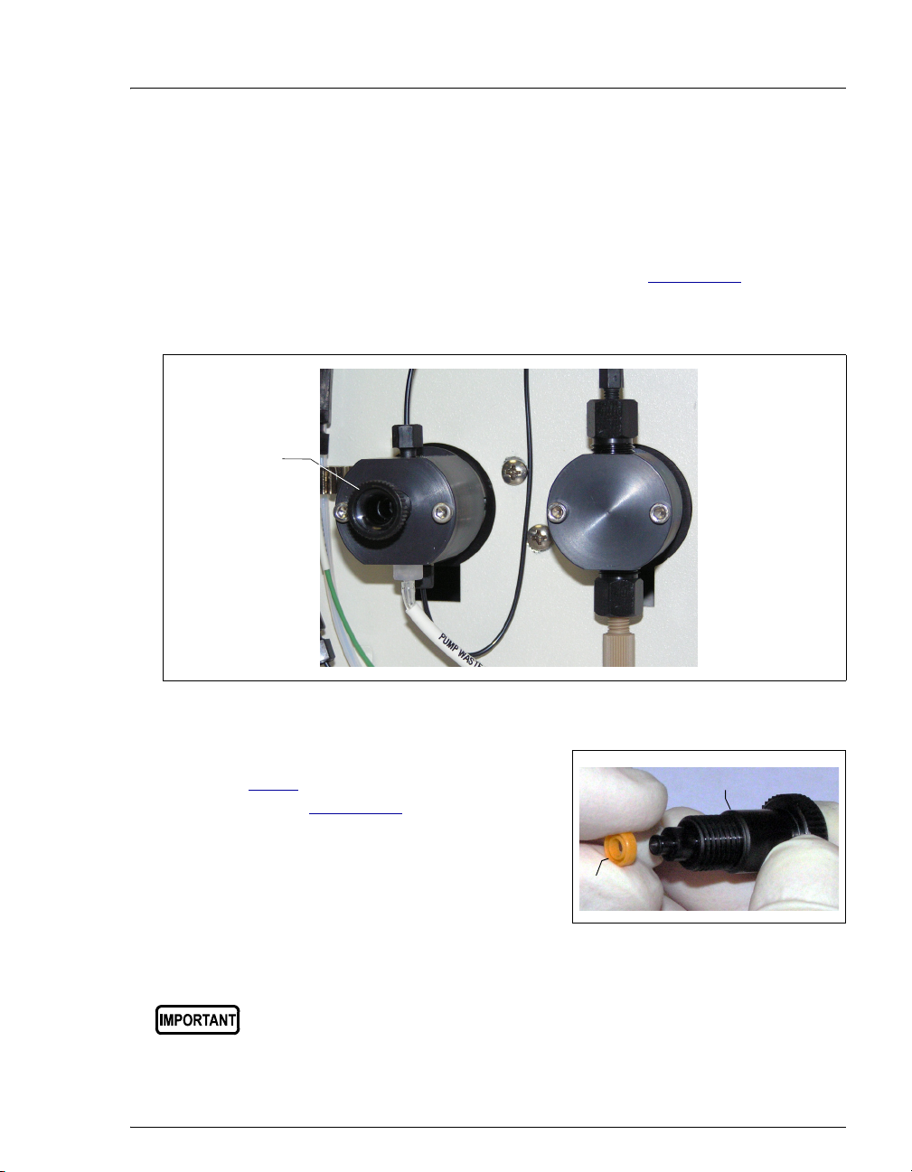
5.9 Replacing the Waste Valve Seal
A damaged seal causes leakage around the base of the waste valve knob.
1. Turn off the ICS-900 power switch.
5•Service
2. To remove the waste valve from the pump head (see Figure 5-12
), turn the
knob counterclockwise until it is loose, and then pull the knob straight out of
the cavity in the pump head.
Waste Valve
Figure 5-12. Waste and Priming Valves
3. If the seal is removed with the valve knob
in Step 2
, pull the seal off the end of the
knob (see Figure 5-13
). If the seal is not
Valve Knob
removed with the valve knob, insert a thin
object (for example, the straightened end
of a paper clip) into the cavity in the
Seal
pump head and carefully pull out the seal.
Do not scratch the cavity.
Figure 5-13. Waste Valve Seal Replacement
Scratches in the cavity will cause leaks around the base of the knob
while the pump is being primed.
Doc. 065215-02 9/09 87
Page 96

ICS-900 Operator’s Manual
4. Orient the new seal (P/N 063382) with the grooved side away from the valve
and slide it over the end of the valve.
5. Insert the valve with the new seal into the pump head opening and turn the
knob clockwise. Tighten fingertight.
6. Turn on the ICS-900 power switch.
7. Prime the pump (see Section 3.6
).
5.10 Rebuilding the Injection Valve
Dionex recommends rebuilding the injection valve annually. The Injection Valve
Rebuild Kit (P/N 057896) contains all required replacement parts.
NOTE Substitution of non-Dionex parts may impair valve
performance and void the product warranty.
1. Turn off the pump.
2. Open the front door of the ICS-900.
3. Disconnect each liquid line connected to the injection valve.
4. Follow the instructions provided in the Injection Valve Maintenance Kit to
replace the rotor seal, isolation seal, and stator face.
5. Reconnect all liquid lines to the injection valve.
6. Close the ICS-900 front door.
7. Turn on the pump from the ICS-900 Control panel.
88 Doc. 065215-02 9/09
Page 97

8. Reset the injection valve cycle counter in
Chromeleon or Chromeleon Xpress:
a. Press F8 to open the Commands dialog
box.
b. Expand the list of commands under
Pump_ECD and scroll to the
ResetInjValveCounter command (see
Figure 5-14
).
c. Select the command and click Execute.
Figure 5-14. Resetting the Injection Valve Counter
5•Service
Doc. 065215-02 9/09 89
Page 98

ICS-900 Operator’s Manual
r
(
)
5.11 Replacing the Conductivity Cell
1. Turn off the ICS-900 power switch.
1. Disconnect the power cord.
2. Open the ICS-900 front door.
3. Disconnect the black
suppressor (see Figure 5-15
t
e
D
5
S
D
CELL OUT (orange)
to CELL OUT
Figure 5-15. Conductivity Cell Assembly
4. Disconnect the orange
CELL OUT line.
black
ELUENT OUT line from the ELUENT OUT port on the
).
r
e
z
i
l
i
b
a
t
S
n
o
i
t
c
e
ELUENT OUT
to suppresso
Connector to component
mounting panel
black
CELL OUT line from the union that connects it to the
5. Use an Allen wrench to remove the two screws on the top of the cell housing.
6. Remove the cell by unplugging it from the component mounting panel.
7. Plug the new conductivity cell (P/N 067761) into its mounting location.
8. Replace the screws on the top of the cell housing and tighten.
9. Attach the orange
CELL OUT line. Attach the ELUENT OUT line to the ELUENT OUT port on
black
the suppressor.
CELL OUT line from the cell to the union attached to the
10. Close the front door.
90 Doc. 065215-02 9/09
Page 99

11. Reconnect the power cord and turn on the ICS-900 power.
5•Service
12. Calibrate the cell (see Section 5.1.4
5.12 Replacing the Suppressor
Refer to the suppressor manual for guidance about when to replace a suppressor.
Suppressor manuals are included on the Dionex Reference Library CD-ROM
(P/N 053891).
1. Turn off the pump.
2. Open the front door of the ICS-900.
3. Disconnect the four eluent and regenerant lines from the suppressor.
4. Slide the suppressor to the left to detach it from the component mounting
panel.
5. Slide the new suppressor to the right until it locks into place on the mounting
panel.
6. Connect the four eluent and regenerant lines to the new suppressor.
7. Close the ICS-900 front door.
8. Prime the pump (see Section 3.6
).
).
Doc. 065215-02 9/09 91
Page 100

ICS-900 Operator’s Manual
5.13 Changing the Main Power Fuses
1. Turn off the ICS-900 power switch.
2. Disconnect the power cord.
HIGH VOLTAGE—Disconnect the main power cord from its source and
also from the rear panel of the ICS-900.
HAUTE TENSION—Débranchez le cordon d'alimentation principal de
sa source et du panneau arrière du ICS-900.
HOCHSPANNUNG—Ziehen Sie das Netzkabel aus der Steckdose und
der Netzbuchse auf der Rückseite des ICS-900.
3. The fuse drawer is located above the
power switch (see Figure 5-16
tab locks the fuse drawer in place. Using
a small screwdriver, press the tab in and
then up to release the fuse drawer.
). A small
Fuse
Drawer
Tab
4. Pull the fuse drawer out of the rear panel
and remove the old fuses.
5. Replace the two fuses with new fast-blow
IEC 127 fuses rated 3.15 A
(P/N 954745). Dionex recommends
always replacing both fuses.
Figure 5-16. Fuse Drawer
6. Insert the fuse drawer into the rear panel and press until the drawer snaps into
place.
7. Reconnect the main power cord and turn on the power.
92 Doc. 065215-02 9/09
 Loading...