

Page 1

ICS-90 Ion Chromatography System
Installation Instructions
Document No. 031856
Revision 03
December 2006
Page 2

© 2006 by Dionex Corporation
All rights reserved worldwide.
Printed in the United States of America.
This publication is protected by federal copyright law. No part of this publication
may be copied or distributed, transmitte d, tr anscribed, stored in a retrieval system, or
transmitted into any human or computer language, in any form or by any means,
electronic, mechanical, magnetic, manual, or otherwise, or disclosed to third parties
without the express written permission of Dione x Corporation , 1228 Titan Way,
Sunnyvale, California 94088-3603 U.S.A.
DISCLAIMER OF WARRANTY AND LIMITED WARRANTY
THIS PUBLICATION IS PROVIDED “AS IS” WITHOUT WARRANTY OF
ANY KIND. DIONEX CORPORATION DOES NOT WARRANT,
GUARANTEE, OR MAKE ANY EXPRESS OR IMPLIED
REPRESENTATIONS REGARDING THE USE, OR THE RESULTS OF T HE
USE, OF THIS PUBLICA TION IN TERMS OF CORRECTNESS, ACCURACY,
RELIABILITY, CURRENTNESS, OR OTHERWISE. FURTHER, DIONEX
CORPORATION RESERVES THE RIGHT TO REVISE THIS PUBLICATION
AND TO MAKE CHANGES FROM TIME TO TIME IN THE CONTENT
HEREINOF WITHOUT OBLIGATION OF DIONEX CORPORATION TO
NOTIFY ANY PERSON OR ORGANIZATION OF SUCH REVISION OR
CHANGES.
TRADEMARKS
Chromeleon® is a registered trademark of Di onex Corporation.
Microsoft® Windows® XP and Windows® 2000 are registered trademarks of
Microsoft Corporation.
PRINTING HISTORY
Revision 01, April 2002
Revision 02, November 2005
Revision 03, December 2006
Page 3

1 • Unpacking the ICS-90 System
1.1 Facility Requirements . . . . . . . . . . . . . . . . . . . . . . . . . . . . . . . . . . . . . . . 1
1.2 Unpacking the ICS-90 System . . . . . . . . . . . . . . . . . . . . . . . . . . . . . . . . 2
1.2.1 Unpacking the ICS-90 . . . . . . . . . . . . . . . . . . . . . . . . . . . . . . . . 2
1.2.2 Removing the Pump Shipping Screw . . . . . . . . . . . . . . . . . . . . . 3
2 • Installing the ICS-90 System
2.1 Installing the Chromatography Software . . . . . . . . . . . . . . . . . . . . . . . . . 5
2.1.1 Installing the Software . . . . . . . . . . . . . . . . . . . . . . . . . . . . . . . . 5
2.1.2 Installing the Software License . . . . . . . . . . . . . . . . . . . . . . . . . 7
2.1.3 Starting the Chromeleon Server Monitor . . . . . . . . . . . . . . . . . 10
Contents
2.2 Connecting the ICS-90 to the Computer . . . . . . . . . . . . . . . . . . . . . . . . 11
2.3 Connecting the Power Cord . . . . . . . . . . . . . . . . . . . . . . . . . . . . . . . . . . 13
2.4 Turning on the ICS-90 Power . . . . . . . . . . . . . . . . . . . . . . . . . . . . . . . . 14
2.5 Setting Up the Chromatography Software . . . . . . . . . . . . . . . . . . . . . . 15
2.5.1 Creating a Timebase . . . . . . . . . . . . . . . . . . . . . . . . . . . . . . . . . 15
2.5.2 Connecting to the Control Panel . . . . . . . . . . . . . . . . . . . . . . . 18
2.5.3 Verifying Communication with the ICS-90 . . . . . . . . . . . . . . . 20
2.6 Connecting the Waste Lines . . . . . . . . . . . . . . . . . . . . . . . . . . . . . . . . . 21
2.7 Connecting the Gas Source . . . . . . . . . . . . . . . . . . . . . . . . . . . . . . . . . . 22
2.8 Setting Up the Eluent and Regenerant Reservoirs . . . . . . . . . . . . . . . . 23
Doc. 031856-03 12/06 i
Page 4

ICS-90 Installation Instructions
2.9 Installing and Plumbing the Columns and Suppressor . . . . . . . . . . . . . .25
2.10 Pressurizing the Eluent Reservoir . . . . . . . . . . . . . . . . . . . . . . . . . . . . . .28
2.11 Priming the Pump . . . . . . . . . . . . . . . . . . . . . . . . . . . . . . . . . . . . . . . . . .29
2.12 Setting the Pump Flow Rate (ICS-90 only) . . . . . . . . . . . . . . . . . . . . . .30
2.12.1 Setting the Flow Rate . . . . . . . . . . . . . . . . . . . . . . . . . . . . . . . .30
2.12.2 Recording the Measured Flow Rate . . . . . . . . . . . . . . . . . . . . .33
2.13 Setting the Pump Flow Rate (ICS-90A only) . . . . . . . . . . . . . . . . . . . . .34
2.14 Equilibrating the System . . . . . . . . . . . . . . . . . . . . . . . . . . . . . . . . . . . .34
2.15 Verifying Operational Status . . . . . . . . . . . . . . . . . . . . . . . . . . . . . . . . .35
2.16 Connecting the AS40 Automated Sampler (Optional) . . . . . . . . . . . . . .35
2.17 Operating the ICS-90 . . . . . . . . . . . . . . . . . . . . . . . . . . . . . . . . . . . . . . .36
2.18 Installation Troubleshooting . . . . . . . . . . . . . . . . . . . . . . . . . . . . . . . . . .36
ii Doc. 031856-03 12/06
Page 5
1 • Unpacking the ICS-90 System
This manual provides instructions for the initial installation of the ICS-90 Ion
Chromatography System (ICS-90). Follow these installation instructions step-bystep, in the order specified.
A newer version of the ICS-90, called the ICS-90A, has a feature that allows the
approximate flow rate to be displayed in Chromeleon
Management System or Chromeleon Xpress. Unless otherwise specified, all of the
information in this manual applies to both the ICS-90 and the ICS-90A. If you are
unsure which system you have, check the model data label on the rear panel.
It is especially important to install Chromeleon or Chromeleon Xpress
before connecting the USB cable from the computer to the ICS-90 and
before turning on the ICS-90 power.
1.1 Facility Requirements
• Make sure the ICS-90 installation site meets the following environmental
specifications:
Operating Temperature: 10 to 35 °C (50 to 95 °F)
® Chromatography
Humidity: 5% to 95% relative humidity, noncondensing
• The ICS-90 requires a sturdy workbench of a height that ensures convenient
access to the interior.
• Allow at least 15 cm (6 in) behind the ICS-90 for power connections and
ventilation. For optimal performance, install the ICS-90 in a draft-free
location, out of the path of air conditioning and heating vents.
• A clean gas source regulated to between 0.55 and 0.83 MPa (80 and 120 psi)
is required for pressurization of the eluent reservoir.
• Use ASTM filtered, Ty pe I (18-megohm) deionized water when preparing
eluent and regenerant.
Doc. 031856-03 12/06 1
Page 6
ICS-90 Installation Instructions
1.2 Unpacking the ICS-90 System
1.2.1 Unpacking the ICS-90
1. Open the shipping box.
2. Remove the eluent reservoir assembly and the ICS-90 Ship Kit
059947).
(P/N
3. Remove the foam cover.
4. Using the cardboard side handles, carefully remove the ICS-90 from
the box. You may need to remove the foam at the sides of the ICS-90
before you can lift the instrument from the box.
Lift the ICS-90 only from each side of the cabinet bottom. Lifting from
the front door will damage the door hinges. Use caution when lifting
the module: it weighs 19 kg (42
Ne soulevez le ICS-90 que par le fond ou les côtés. Son soulèvement
par la porte du panneau avant endommagera les charnières de la
porte. Soyez prudent lorsque vous soulevez le ICS-90: il pèse 19 kg
lb).
(42
lb).
Heben Sie das ICS-90 nur an, indem Sie von beiden Seiten unter den
Boden greifen. Wenn Sie das Gerät an der Vordertür anheben,
beschädigen Sie die Türangeln. Vorsicht beim Heben des Moduls: Es
wiegt 19 kg.
5. Set the ICS-90 on a workbench and cut the tape to remove the plastic
surrounding the instrument.
6. Inspect the ICS-90 for any shipping damage.
2 Doc. 031856-03 12/06
Page 7
1 • Unpacking the ICS-90 System
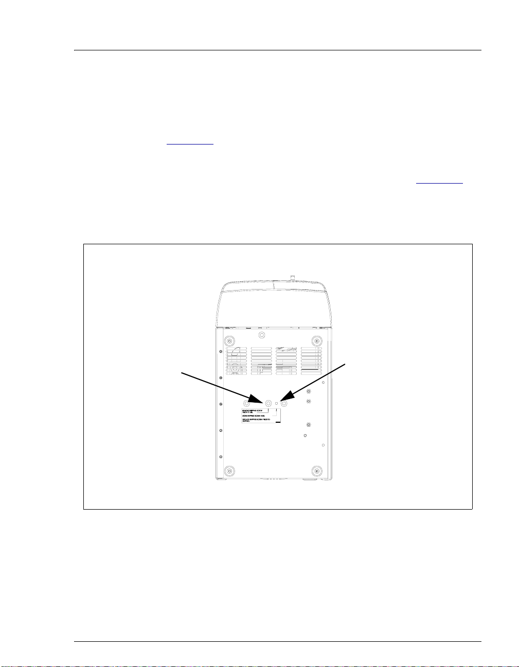
1.2.2 Removing the Pump Shipping Screw
1. Carefully lay the ICS-90 on its back or side.
2. Locate the middle screw on the bottom of the ICS-90 (see
Figure 1-1). This screw secures the pump in place during shipment.
3. Use a Phillips screwdriver to remove the shipping screw.
4. A screw holder is located to the right of the screw (see Figure 1-1).
Place the screw in the holder for safekeeping. You will need to
reinstall the screw if the ICS-90 is shipped to another location.
5. Return the ICS-90 to an upright position.
Front
Shipping Screw
Screw Holder
Bottom View of ICS-90
Rear
Figure 1-1. Pump Shipping Screw Removal
Doc. 031856-03 12/06 3
Page 8

ICS-90 Installation Instructions
1.2.3 Unpacking the Computer
Outside North America
1. Remove the computer and all documentation from the computer box
and place them on a workbench.
2. Chromeleon and Chromeleon Xpress run under the Microsoft®
Windows® XP and Windows® 2000 operating systems. Refer to
http://www.dionex.com to verify that the PC meets current system
specifications.
3. Follow the instructions in the computer installation guide to hook up
the PC components.
4. When you finish, go to Section 2.1 to install the chromatography
software.
North America Only
NOTE These instructions assume that Chromeleon or
Chromeleon Xpress and the software license were
installed on the PC before shipment from Dionex.
1. Remove the computer and all documentation from the computer box
and place them on a workbench.
2. Follow the instructions in the computer installation guide to hook up
the PC components.
3. When you finish, go to Section 2.2 to connect the PC to the ICS-90.
4 Doc. 031856-03 12/06
Page 9

2 • Installing the ICS-90 System
2.1 Installing the Chromatography Software
2.1.1 Installing the Software
NOTE Dionex strongly recommends installing Chromeleon
or Chromeleon Xpress chromatography software
before connecting the ICS-90 to the computer on
which the software is installed. When the
chromatography software is installed first, USB
driver information is loaded automatically and the
Windows operating system will detect the ICS-90
when the power is turned on.
The SETUP.EXE file on the Chromeleon CD-ROM installs Chromeleon
or Chromeleon Xpress. After presenting a series of options for your
consideration, the Setup program then copies the software onto the hard
disk.
1. If this is a local computer, log onto W indows XP or Windows 2000 as
an administrator. If this is a network computer, log on as a user with
local computer administrator privileges.
If necessary, ask the computer systems administrator for temporary
administrator privileges. (Administrator privileges are required to
install Chromeleon or Chromeleon Xpress, but not to operate it.)
2. Verify that the drive on which you plan to install the Chromeleon or
Chromeleon Xpress application has at least 250
MB of free disk
space. This is the amount of free disk space required for operation.
Chromeleon only: 250 MB may not be enough disk space to store
the large amounts of data that Chromeleon can generate. If necessary ,
you can store data at a different location (for example, on a network).
Doc. 031856-03 12/06 5
Page 10

ICS-90 Installation Instructions
3. Insert the Chromeleon CD-ROM into the PC drive. The Chromeleon
Setup menu should appear.
If the Setup menu does not appear automatically, go to the Autorun
folder on the Chromeleon CD-ROM and double-click autorun.exe.
(The .exe extension is not always visible; it depends on the computer
settings.)
4. Select Launch Chromeleon Setup.
5. Setup now guides you through the installation procedure; follow the
on-screen instructions as they appear.
6. When prompted whether to add the Server Monitor program to the
Startup group, select Yes if the computer will be physically connected
to devices or No if the computer will never be connected to devices.
When Yes is sele cted, the Server Monitor automatically starts when
the computer is started and the program icon is displayed on the
taskbar.
7. After installing the software, restart the computer.
8. Microsoft Windows should automatically detect the ICS-90 and
launch the Found New Hardware Wizard. (If this does not happen,
refer to the
Troubleshooting Tip below.) Complete the wizard by
selecting the following options:
a. If asked whether Windows can connect to Windows Update to
search for software, select No, not this time.
b. Accept the default option (Install the software automatically)
and click Next >.
c. When the wizard reports that the software for the module has
been installed, click Finish.
Troubleshooting Tip
If a Microsoft Windows message box asks for the USB configuration file
(cmwdmusb.inf), it indicates that you connected the ICS-90 to the PC and
turned on the ICS-90 power before installing Chromeleon or Chromeleon
Xpress.
Follow these steps to resolve the problem:
1. Click Cancel in the Windows message box.
6 Doc. 031856-03 12/06
Page 11

2 • Installing the ICS-90 System
2. Turn off the power to the ICS-90 and unplug the USB cable from the
computer.
3. Install Chromeleon or Chromeleon Xpress.
4. Reconnect the USB cable to the computer and turn on the power to
the ICS-90. Windows will now automatically recognize the ICS-90.
2.1.2 Installing the Software License
In order for the Chromeleon or Chromeleon Xpress computer to control
the ICS-90, a valid software license must be installed. To install the
license, you must first install a dongle on the computer and then enter a
license Key Code in Chromeleon. (A dongle is an adapter that is
connected to the parallel PC interface or USB port. The dongle stores the
serial number of a Chromeleon computer.)
NOTE If the software license is managed via a License
Server, a dongle is not required.
1. Plug the dongle into the appropriate port on the computer (either a
parallel or USB port, depending on the type of dongle). For a parallel
port dongle, be sure to tighten the connector screws.
2. If it is not already running, start the Chromeleon Server Monitor
(select Start
> Chromeleon > Server Monitor).
The Server Monitor window opens.
Doc. 031856-03 12/06 7
Page 12
ICS-90 Installation Instructions
• If Chromeleon or Chromeleon Xpress was installed on the
computer before shipping, the Server Monitor status will display
“Chromeleon Server is running idle.” (This is because the license
Key Code was entered before shipping.) If this is the case, click
Close and go
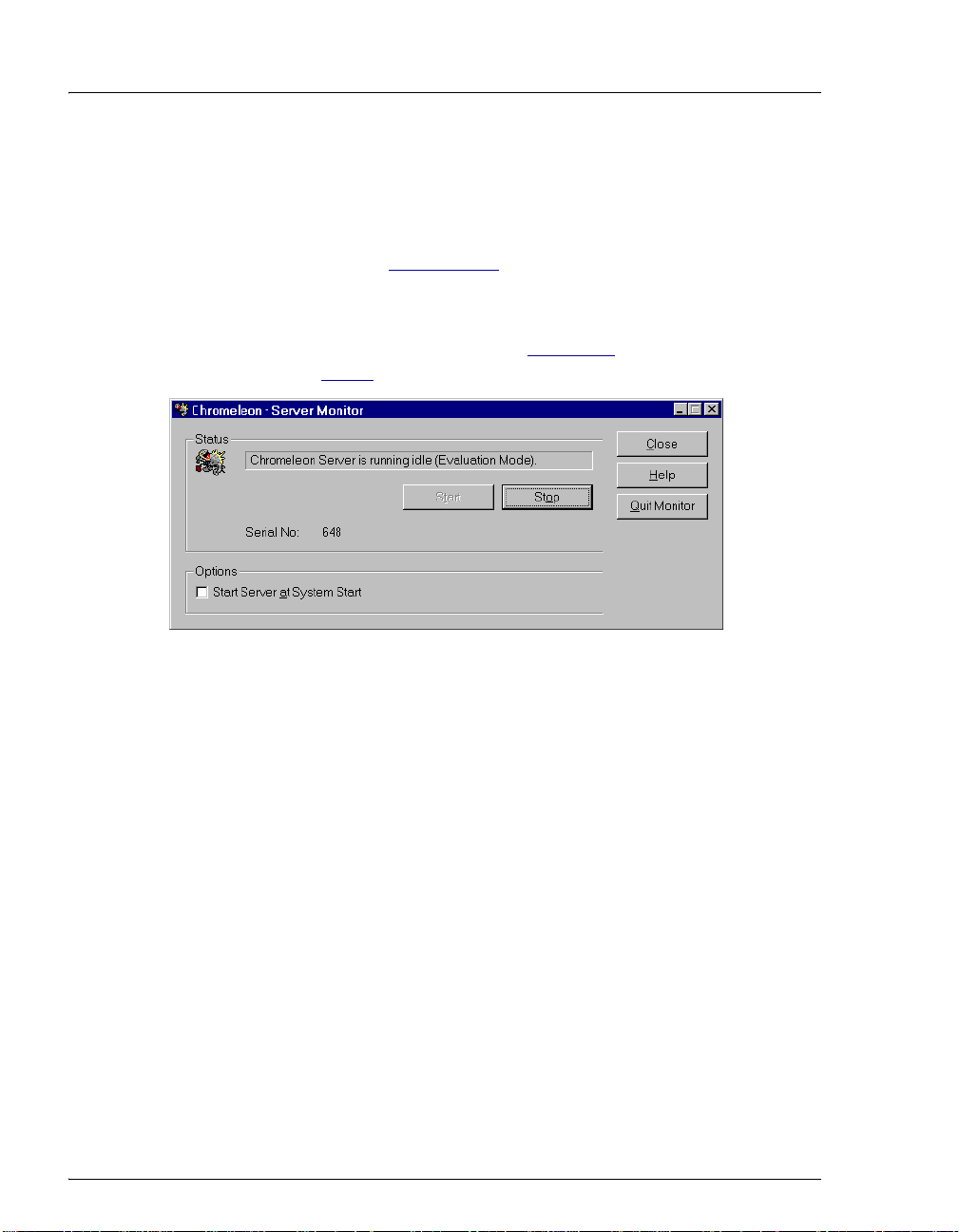
• If Chromeleon or Chromeleon Xpress was not pre-installed, the
Server Monitor status displays “Chromeleon Server is running
idle (Evaluation Mode).”
on to Step 3.
Section 2.5.1 to create a timebase.
(see Figure 2-1). If this is the case, go
Figure 2-1. Server Evaluation Mode
3. Open the Chromeleon Server Configuration program (select Start >
Chromeleon
> Server Configuration).
8 Doc. 031856-03 12/06
Page 13

2 • Installing the ICS-90 System
4. Select Edit > Properties to open the Server Configuration properties
dialog box
Code provided with the Chromeleon license. Click OK.
(see Figure 2-2). Click Dongle and then enter the Key
Figure 2-2. Server Configuration Properties
5. Check the Server Monitor status. It should now display “Chromeleon
Server is running idle.”
Figure 2-3. Server Running
(see Figure 2-3).
6. Click Close to close the Server Monitor window.
Doc. 031856-03 12/06 9
Page 14

ICS-90 Installation Instructions
2.1.3 Starting the Chromeleon Server Monitor
1. If the Chromeleon Server Monitor program did not start
automatically , start it now by double-clicking the Serv er Monitor icon
on the Windows taskbar.
If the Server Monitor icon is not on the taskbar, click Start on the
taskbar and select All Programs (or Programs, depending on the
operating system) > Chromeleon > Server Monitor.
2. If the server is not already running, start it by clicking Start.
3. Click Close to close the Server Monitor program window.
The Server Monitor icon appears on the taskbar.
NOTE Clicking the Quit Monitor button quits (or
exits) the Server Monitor program, but does not
stop the server. To stop the server, click the Stop
button.
10 Doc. 031856-03 12/06
Page 15

2 • Installing the ICS-90 System
2.2 Connecting the ICS-90 to the Computer
The ICS-90 rear panel (see Figure 2-4) provides one USB receptacle. Select one
of the following methods for connecting the ICS-90 to the PC on which
Chromeleon or Chromeleon Xpress is installed:
• Connect the ICS-90 directly to a USB port on the PC.
• If there are no unused USB ports on the PC, connect the ICS-90 to an external
USB hub (P/N 060392) and connect the PC to the hub.
If the dongle provided with Chromeleon or Chromeleon Xpress is for a USB port,
remember to reserve a USB port on either the PC or the hub for the dongle.
Before connecting the USB cable and turning on the ICS-90 power,
verify that Chromeleon or Chromeleon Xpress is installed on the PC
(see Section 2.1.1).
USB
Receptacle
TTL
Connector
Power Switch
Main Power
Receptacle
Waste Lines
Liquid Lines
Figure 2-4. ICS-90 Rear Panel
Doc. 031856-03 12/06 11
Page 16

ICS-90 Installation Instructions
To connect the ICS-90 directly to the PC:
1. Locate the USB cable (P/N 960777) provided in the ICS-90 Ship Kit
059947).
(P/N
2. Plug the “A” connector of the USB cable into the USB port on the PC
(see Figure 2-5).
3. Plug the “B” connector of the USB cable into the USB receptacle on
the ICS-90 rear panel
ICS-90
B
(P/N 960777)
(see Figure 2-5).
USB Cable
Plug the “B”
connector
receptacle on the ICS-90.
USB cable’s
into the USB
A
Plug the “A”
connector the
port on the PC.
PC
USB cable’s
into USB
Figure 2-5. Example Connections: One ICS-90 Connected to the Computer
To connect the ICS-90 to an external hub (P/N 060392):
The ICS-90 Ship Kit (P/N 059947) includes one USB cable
(P/N
960777). You must o r der another USB cable for this configuration.
The USB standard limits the USB cable length to 5 m (5.5 yds). Each
USB device can be separated from the PC by no more than five hubs.
Thus, each USB device can be located no more than 30
from the PC.
Carefully secure all USB cables, the external hub, and the hub po wer
cable so that they cannot be accidentally disconnected.
m (32 yds)
1. Plug the “A” connector of a USB cable into a port on the external
USB hub
(see Figure 2-6).
2. Plug the “B” connector of the cable into the USB receptacle on the
ICS-90 rear panel
(see Figure 2-6).
12 Doc. 031856-03 12/06
Page 17

2 • Installing the ICS-90 System
USB
Device
B
A
A
B
Plug the USB cable’s “A” connector
into the USB port on the PC.
Plug the USB cable’s “B” connector
into the “B” port on the USB hub.
PC
ICS-90
B
Plug the USB cable’s “B” connector
into the USB receptacle on the ICS-90.
Plug the USB cable’s “A” connector
into the “A” port on the USB hub.
USB
Device
B
USB Cables
A
A
USB Hub
Figure 2-6. Example Connections: Multiple Modules Connected to an External Hub
3. Plug the “A” connector of a USB cable into a USB port on the
computer
(see Figure 2-6).
4. Plug the “B” connector of the cable into a port on the USB hub.
2.3 Connecting the Power Cord
1. A label on the ICS-90 rear panel indicates the line frequency (60 Hz or 50 Hz)
and voltage (110 to 120 VAC or 220 to 240 VAC) for which the system is
designed. Make sure the frequency and voltage are appropriate for your
location. If you are unsure, consult an electrician.
2. Connect the power cord (IEC 320 C13) from the main power receptacle on
the rear panel
SHOCK HAZARD—To avoid electrical shock, use a grounded
receptacle. Do not operate the ICS-90 or connect it to AC power mains
without an earthed ground connection.
The power supply cord is used as the main disconnect device. Make
sure the socket-outlet is located near the ICS-90 and is easily
accessible.
Doc. 031856-03 12/06 13
(see Figure 2-4) to a grounded power source.
Page 18

ICS-90 Installation Instructions
Operation at AC input levels outside of the specified operating voltage
range may damage the ICS-90.
DANGER D'ÉLECTROCUTION—Pour éviter toute électrocution, il faut
utiliser une prise de courant avec prise de terre. Ne l'utilisez pas et ne
le branchez pas au secteur C.A. sans utiliser de branche ment m is à la
terre.
Le cordon d'alimentation principal est utilisé comme dispositif
principal de débranchement. Veillez à ce que la prise de base soit
située/installée près du module et facilement accessible.
STROMSCHLAGGEFAHR—Zur Vermeidung von elektrischen
Schlägen ist eine geerdete Steckdose zu verwenden. Das Gerät d arf
nicht ohne Erdung betrieben bzw. an Wechselstrom angeschlossen
werden.
Das Netzkabel ist das wichtigste Mittel zur Stromunterbrechung.
Stellen Sie sicher, daß sich die Steckdose nahe am Gerät befindet und
leicht zugänglich ist.
2.4 Turning on the ICS-90 Power
Before turning on the ICS-90 power, verify that Chromeleon or
Chromeleon Xpress is installed. If the chromatography software is not
installed first, the Windows operating system will be unable to identify
the new USB device.
1. Turn on the computer power. If this is a local computer, log onto Windows XP
or Windows 2000 as an administrator. If this is a network computer, log on
as a user with local computer administrator privileges.
2. Turn on the power to the ICS-90. The operating system automatically detects
the new USB device. A message flashes on the screen to inform you that the
device was detected.
14 Doc. 031856-03 12/06
Page 19

2 • Installing the ICS-90 System
2.5 Setting Up the Chromatography Software
2.5.1 Creating a Timebase
1. In the Server Configuration program, select Edit > Add Timebase.
2. A clock icon appears under the server name with a default name
highlighted. To use the default name, press Enter. To use a different
name, type the name and press Enter.
timebase named ICS-90.
Figure 2-7 shows an example
Figure 2-7. Example: Creating a Timebase
3. Select Edit > Add Device. The Add device to timebase dialog box
appears.
Figure 2-8. Add Device to Timebase Dialog Box
Doc. 031856-03 12/06 15
Page 20

ICS-90 Installation Instructions
4. Select ICS-90 IC System from the list and click OK. A dialog box
appears.
Figure 2-9. ICS-90 Configuration Properties: Live Mode
5. On the General tab page, Live Mode is selected by default. Select
the ICS-90 serial number from the drop-down list. If you are
installing more than one ICS-90, you can verify the serial number for
each system by checking the label at the top of the component panel
(see Figure 2-16).
16 Doc. 031856-03 12/06
Page 21

2 • Installing the ICS-90 System
6. Click Options to display the Options tab page.
7. Select the conductivity range (0 to 500 μS or 0 to 10,000 μS) from the
drop-down list under Set Detection Limits. Selecting the larger
(coarse) range reduces the detector’s resolution by a factor of 20.
NOTE The Set Detection Limits option is not enabled
unless Moduleware version >1.3 is installed in
your ICS-90.
8. Click OK to close the properties dialog box.
9. Save the configuration (select File > Save Installation).
10. The Server Configuration Check message window appears. You can
ignore the “no inject device installed” warning, if it appears. This
simply means that the timebase does not include an autosampler.
Click Close.
11. Exit the Server Configuration program.
Doc. 031856-03 12/06 17
Page 22

ICS-90 Installation Instructions
2.5.2 Connecting to the Control Panel
1. Click Start on the Windows taskbar and select All Programs (or
Programs) > Chromeleon > Chromeleon to start the Chromeleon
client.
2. If Chromeleon is installed, select View > Default Panel Tabset or
click
on the toolbar to display the panel tabset.
NOTE If Chromeleon Xpress is installed, starting the
client automatically displays the panel tabset.
3. To display the ICS-90 (or ICS-90A) Control panel (see Figure 2-10),
select the ICS-90 tab on the panel tabset. (The ICS-90A Control
panel includes a Wellness Panel button; otherwise, the panels are
identical.)
Figure 2-10. ICS-90 Control Panel on the Panel Tabset
18 Doc. 031856-03 12/06
Page 23

2 • Installing the ICS-90 System
4. If a “Cannot connect to timebase…” message appears, click OK to
close it.
NOTE If the timebase was named “ICS-90” when it
was created, the Control panel opens and
connects automatically to the ICS-90 timebase.
5. If the Control panel opens with the controls not yet active, connect the
ICS-90 to the Control panel by clicking the Connect button.
A dialog box appears (see Figure 2-11).
Figure 2-11. Connect to Timebase
6. Click the plus sign beside My Computer on the right side of the
dialog box and select the timebase you created in
Section 2.5.1. Click
OK to close the dialog box.
The controls on the panel are now connected
Doc. 031856-03 12/06 19
Page 24

ICS-90 Installation Instructions
2.5.3 Verifying Communication with the ICS-90
T o verify that Chromeleon or Chromeleon Xpress is communicating with
the ICS-90, click the
Control panel while observing the ICS-90 front panel LEDs.
If the ICS-90 and the chromatography software are communicating
correctly, the
Power and Ready LEDs are on when the ICS-90 is
connected to Chromeleon or Chromeleon Xpress, and only the
LED is on when it is disconnected.
Figure 2-12. ICS-90 LEDs Connected and Disconnected States
Disconnect and then the Connect button on the
Power
20 Doc. 031856-03 12/06
Page 25

2 • Installing the ICS-90 System
2.6 Connecting the Waste Lines
Untape the coiled waste and liquid lines from the rear panel. Place the ends of the
three waste lines into a waste container. The waste lines siphon off prime waste
from the pump head, sample overflow from the injection valve, and system waste
from the suppressor.
NOTE To prevent waste from siphoning back into the system,
check the lines periodically to be sure they are not bent,
pinched, or elevated at any point.
A DCR waste backpressure tubing assembly (P/N 060214) is installed
on the free end of the MMS III waste line
assembly consists of a coupler and a 6-inch length of 0.25-mm
(0.010-in) ID black tubing.
The tubing assembly provides a small amount of backpressure to
compress any air bubbles formed in the suppressor’s regenerant
chamber. If you shorten or replace the MMS III waste line, remember to
reinstall the backpressure tubing assembly. Failure to do so will result
in high baseline drift.
(see Figure 2-13). The
Coupler
Suppressor
Waste Line
0.25-mm (0.010-in) ID
Black Tubing
Figure 2-13. DCR Waste Backpressure Tubing Assembly
Doc. 031856-03 12/06 21
Page 26

ICS-90 Installation Instructions
2.7 Connecting the Gas Source
1. Locate the barbed fitting (P/N 030071), pipe thread reducer (P/N 030087),
3-mm (1/8-in) ID tubing (P/N 040793), and ICS-90 air regulator accessory
060054) in the ICS-90 Ship Kit.
(P/N
2. Use the barbed fitting and pipe thread reducer to connect the 3-mm (1/8-in)
ID tubing to a clean gas source. The gas source should be regulated to
between 0.55 and 0.83 MPa (80 and 120
3. Push the other end of the tubing onto the inlet of the air regulator (see
Figure 2-14).
NOTE Do not turn on the gas source. Do not pressurize until
the eluent is prepared and the ICS-90 is plumbed.
psi).
Eluent Gas Line
Gas Inlet Line
3-mm (1/8-in) ID
Connect to gas
source
Figure 2-14. ICS-90 Air Regulator Accessory
22 Doc. 031856-03 12/06
Page 27

2 • Installing the ICS-90 System
2.8 Setting Up the Eluent and Regenerant Reservoirs
1. Rinse the eluent and regenerant reservoirs.
2. Prepare 2 L of eluent. For instructions, see the manual for the column being
installed. The column manual is included on the Dionex Reference Library
CD-ROM (P/N 055405), located in the Ship Kit.
3. Follow the instructions below to prepare either anion (dilute sulfuric acid) or
cation (tetrabutylammonium hydroxide (TBAOH)) regenerant.
a. Fill the regenerant reservoir (anion, P/N 057712; cation, P/N 057713)
about halfway with ASTM filtered, Ty pe I (18-megohm) deionized (DI)
water.
For acid concentrates (such as the anion regenerant), always pour the
concentrate into deionized water, not into the empty reservoir.
Pour les concentrés acides (comme le régénérant an ionique), versez
toujours le concentré dans de l'eau désionisée et non dans le
réservoir vide.
Gießen Sie bei säurehaltigen Konzentraten (beispielsweise dem
Kationenelutionsmittel) das Konzentrat immer in entionisiertes
Wasser und nicht in den leeren Behälter.
b. Empty the entire bottle of concentrate into the reservoir.
c. Fill the concentrate bottle with DI water and empty the contents into the
reservoir.
d. Continue to pour DI water into the reservoir until it is filled all the way to
the top. If a few drops spill over, then it is full enough.
The regenerant reservoir must be filled all the wa y to the top at all
times.
e. Insert the stopper assembly tubing into the reservoir and tighten the
stopper.
Do not shake the regenerant reservoir to mix the contents. The ICS-90
will stratify the content s .
Doc. 031856-03 12/06 23
Page 28

ICS-90 Installation Instructions
For additional information, refer to the Installation Instructions and
Troubleshooting Guide for the Displacement Chemical Regeneration
(DCR) Kit (Document No. 031664). The manual is included on the
Dionex Reference Library CD-ROM (P/N 055405), located in the ICS-90
Ship Kit.
4. Make sure the regenerant reservoir is filled almost to overflowing.
5. Slip the air regulator accessory bracket over the neck of the eluent reservoir.
6. Install the caps on the eluent and regenerant reservoirs and hand tighten.
7. Place the reservoirs in the holders on the top cover of the ICS-90.
8. Connect the liquid lines from the ICS-90 to the lines exiting the eluent and
regenerant reservoir caps
a. Connect the two lines labeled Eluent Bottle Out.
b. Connect the two lines labeled Regen Bottle Out.
c. Connect the line labeled Regen In to the green Regen Bottle In line from
the ICS-90.
(see Figure 2-15) as follows:
Eluent Bottle
Out Line
Eluent Gas
Line
Regen Bottle
Out Line
Regen Bottle
In Line
Gas Inlet Line
(from gas source)
Figure 2-15. Reservoir Connections
24 Doc. 031856-03 12/06
Page 29

2 • Installing the ICS-90 System
9. To ensure the correct operating pressure for the suppressor, either one or two
backpressure coil(s) (P/N 045877) must be installed between the cell outlet
and the regenerant reservoir inlet. The number of coils required depends upon
the application flow rate:
Application Flow Rate Number of Required
Backpressure Coils
Less than 2 mL/min 2
2 mL/min or more 1
a. For flow rates less than 2 mL/min, verify that two coils are installed.
b. For flow rates of 2 mL/min or more, remove one of the backpressure
coils.
NOTE Refer to the flier Backpressure Coil Pressure Test for
Dionex Suppressors (Document No. 031759)
(shipped with the suppressor) for details about
suppressor operating pressure requirements.
10. Connect the orange gas line from the eluent reservoir to the gas line on the air
regulator outlet.
2.9 Installing and Plumbing the Columns and Suppressor
NOTE This section provides brief installation and plumbing
instructions for the columns and suppressor. For
detailed installation information, refer to the column
and suppressor manuals provided on the Dionex
Reference Library CD-ROM (P/N 055405).
1. Remove the guard column, separator column, and MMS III suppressor from
their boxes. Remove the fitting plugs from the ends of each column and from
all ports on the suppressor. Discard the tubing that temporarily connected the
suppressor ports.
2. Plumb the guard and separator columns. Refer to the labels on the tubing, to
Figure 2-16, and to the following instructions.
Doc. 031856-03 12/06 25
Page 30

ICS-90 Installation Instructions
a. Remove the union connecting GUARD IN and GUARD OUT and connect
GUARD IN to the guard column inlet. Check the arrow on the column
label; it should point away from the injection valve.
b. Connect GUARD OUT to the guard column outlet.
c. Push the guard column onto the clips.
d. Remove the union connecting COL IN and COL OUT and connect COL IN to
the separator column inlet. Connect
outlet. Check the arrow on the column label. It should point toward the
cell (DS5).
e. Push the column onto the clips.
COL OUT to the separator column
Serial Number
Eluent
In/Out
Union
(remove)
Cell Out
Union
Verify that 1
or 2 back-
pressure
coils are
installed (not
shown in
photo)
Column
In/Out
Union
(remove)
Regen In/Out
Union (remove)
Suppressor
Brackets
Do not
remove
Guard In/Out Union (remove)
Figure 2-16. ICS-90 Component Panel (Door not shown)
26 Doc. 031856-03 12/06
Page 31

3. Plumb the MMS III suppressor as follows:
a. Install the suppressor onto the brackets located below the DS5 (see
Figures 2-16
and 2-17).
b. Remove the union connecting ELUENT IN and ELUENT OUT and connect
ELUENT IN
and ELUENT OUT to the corresponding ports on the suppressor.
c. Remove the union connecting REGEN IN and REGEN OUT and connect
REGEN IN and REGEN OUT to the corresponding ports on the suppressor.
MMS III
Suppressor
Separator
Column
2 • Installing the ICS-90 System
Side slot for
Guard Column
autosampler
line
Figure 2-17. ICS-90 with Columns and Suppressor Installed
4. To ensure the correct operating pressure for the suppressor, either one or two
backpressure coil(s) (P/N 045877) must be installed between the cell outlet
and the regenerant reservoir inlet. The number of coils required depends upon
the application flow rate:
Application Flow Rate Number of Required
Backpressure Coils
Less than 2 mL/min 2
2 mL/min or more 1
Doc. 031856-03 12/06 27
Page 32

ICS-90 Installation Instructions
a. For flow rates less than 2 mL/min, verify that two coils are installed.
b. For flow rates of 2 mL/min or more, remove one of the backpress ure
coils.
NOTE Refer to the flier Backpressure Coil Pressure Test for
Dionex Suppressors (Document No. 031759)
(shipped with the suppressor) for details about
suppressor operating pressure requirements.
2.10 Pressurizing the Eluent Reservoir
NOTE Do not pressurize the regenerant reservoir.
1. Pull out the air regulator knob and turn it fully counterclockwise to ensure
there is no pressure to the reservoir when the gas source is turned on.
2. Turn on the gas source.
3. Pull out the air regulator knob and turn it clockwise to pressurize the eluent
reservoir.
4. Adjust the pressure to between 30 and 40 kPa (5 and 6 psi). Push the regulator
knob back in.
Do not pressurize the eluent reservoir above 70 kPa (10 psi).
Ne mettez jamais les réservoirs d'éluants sous une pression
supérieure à 0,07 MPa (10 lb/po²).
Setzen Sie den Eluentbehälter auf keinen Fall einem Druck über
0,07
MPa aus.
28 Doc. 031856-03 12/06
Page 33

2.11 Priming the Pump
1. Verify that the eluent and regenerant reservoirs are filled, the reservoir caps
are installed and hand-tightened, and the gas and liquid lines are connected to
the reservoirs
2. Verify that the gas supply is turned on, the eluent reservoir is pressurized (see
Section 2.10), and the regenerant reservoir is unpressurized. Note: The
regenerant reservoir is unpressurized if the reservoirs are connected as
described in
3. Verify that the waste lines are directed to a waste container.
4. To start the liquid flow, open the pump head waste valve (see Figure 2-18) by
turning the knob counterclockwise two turns. When the valve is open, eluent
flows directly from the pump to waste.
(see Section 2.8).
Section 2.8.
2 • Installing the ICS-90 System
Pulse
Damper
Pump Head
Waste Valve
Pump Flow
Rate Knob
Figure 2-18. ICS-90 Interior Components
5. Let the liquid flow for at least 2 to 3 minutes to ensure that there are no
trapped gas bubbles in the line from the eluent reservoir to the pump head.
Doc. 031856-03 12/06 29
Page 34

ICS-90 Installation Instructions
6. Turn on the pump from the ICS-90 (or ICS-90A) Control panel in
Chromeleon or Chromeleon Xpress. Allow the pump to run with the waste
valve open for 30 seconds.
7. Close the waste valve knob.
2.12 Setting the Pump Flow Rate (ICS-90 only)
The instructions in this section apply to the ICS-90 only. If you are unsure
whether your system is an ICS-90 or ICS-90A, check the model data label on the
rear panel.
2.12.1 Setting the Flow Rate
1. Locate the production test chromatogram on the Dionex Quality
Assurance Report (supplied with the separator column). Note the
backpressure and flow rate listed for the column.
2. Pull out the flow rate knob on the component mounting panel (see
Figure 2-18) and turn the knob slowly to the right to begin adjusting
the pressure.
NOTES
• There is about a 10-second delay between adjusting the knob and
the pressure reading response on the ICS-90 Control panel in
Chromeleon or Chromeleon Xpress.
• The flow rate on the ICS-90 Control panel is a recorded value only
and does not change when the flow rate knob is adjusted.
3. Adjust the knob until the pump pressure reading on the ICS-90
Control panel reaches the figure listed on the production test
chromatogram.
NOTE The production test chromatogram is produced
without a guard column. If a guard column is
installed, adjust the knob until the pressure is about
1.4 to 2.1
backpressure listed for the separator column alone.
30 Doc. 031856-03 12/06
MPa (200 to 300 psi) above the
Page 35

2 • Installing the ICS-90 System
4. Measure the flow rate, using one of the following methods:
• Volumetrically (recommended for most applications): Measure
the volume of liquid collected over a measured time period. The
ICS-90 Ship Kit includes items for measuring the flow rate
volumetrically.
• Gravimetrically: Weigh the mass of liquid collected over a
measured time period. The gravimetric method is slightly more
accurate than the volumetric method.
Volumetric Method 1 (Recommended): Using a Syringe and Adapter
a. Locate the following items in the ICS-90 Ship Kit: luer fitting
(P/N 024305), luer coupler (P/N 042806), 1 mL syringe (P/N 016388),
and 10 mL syringe (P/N 016387). You will also need a stopwatch or a
clock or watch with a second hand (the computer’s clock can be used),
and a small beaker or other container for collecting waste.
b. Connect the luer coupler to the luer fitting.
c. Select the syringe to be used:
• For a 0.5 mL/min flow rate, use the 1 mL syringe.
• For a flow rate above 0.5 mL/min, use the10 mL syringe.
d. Disconnect the ELUENT IN line from the ELUENT IN port on the
ELUENT IN line, and connect
Syringe
suppressor. Connect the luer coupler to the
the syringe to the luer fitting
Figure 2-19. Assembled Syringe and Luer Adapter
(see Figure 2-19).
Eluent In
Line
Luer
Coupler
Luer
Fitting
Doc. 031856-03 12/06 31
Page 36

ICS-90 Installation Instructions
e. Using a stopwatch or clock’s second hand, time the flow of eluent into the
syringe for 60 seconds. Determine the volume collected by noting the
beginning and ending positions of the syringe plunger.
f. The volume of eluent collected in 60 seconds should be approximately
equal to the desired flow rate in milliliters per minute. For example, for a
flow rate of 1 mL/min, the volume should be 1.0
g. If necessary, adjust the flow rate knob, and then repeat the measurement.
Continue adjusting until the desired milliliters per minute is collected.
h. Reconnect the ELUENT IN line to the suppressor.
Volumetric Method 2: Using a Graduated Cylinder
a. Disconnect the ELUENT IN line from the ELUENT IN port on the
suppressor.
b. Using a clock or watch with a second hand (the computer’s clock can be
used), collect eluent from the
cylinder for 2 minutes.
c. The collected eluent should be approximately equal to the desired flow
rate in milliliters per minute. For example, for a flow rate of 1 mL/min,
± 0.2 mL should be collected in 2 minutes.
2.0
± 0.1 mL.
ELUENT IN line into a small graduated
d. If necessary, adjust the flow rate knob, and then repeat the measurement.
Continue adjustments until the desired eluent per minute is collected.
e. Reconnect the ELUENT IN line to the suppressor.
Gravimetric Method
a. Disconnect the ELUENT IN line from the ELUENT IN port on the
suppressor.
b. Using a tared beaker and a calibrated stopwatch, collect the eluent from
ELUENT IN line for 60 seconds.
the
c. Weigh the mass of the eluent. The mass (in grams) should be
approximately equal to the desired flow rate in milliliters per minute. For
example, for a flow rate of 0.5 mL/min, the mass of the collected eluent
should be 0.5
± 0.02 g.
d. If necessary, adjust the flow rate knob, and then repeat Steps b and c.
Continue adjusting until the desired mass per minute is collected.
e. Reconnect the ELUENT IN line to the suppressor.
32 Doc. 031856-03 12/06
Page 37

2 • Installing the ICS-90 System
2.12.2 Recording the Measured Flow Rate
1. From the ICS-90 Control panel, press the F8 key or select Control >
Command.
2. Expand the Pump_ECD group and select MeasuredFlowRate (see
Figure 2-20).
Figure 2-20. ICS-90 Chromeleon Commands: MeasuredFlo wRate
3. Enter the flow rate and click Execute. Click Close. The measured
flow rate is now shown on the Control panel.
Doc. 031856-03 12/06 33
Page 38

ICS-90 Installation Instructions
2.13 Setting the Pump Flow Rate (ICS-90A only)
NOTE The instructions in this section apply to the ICS-90A
only. If you ar e unsur e whether your system is an ICS-90
or ICS-90A, check the model data label on the rear
panel.
The ICS-90A has a feature that allows the approximate flow rate to be displayed
on the Control panel in Chromeleon or Chromeleon Xpress. The accuracy of the
displayed flow rate depends on the flow rate at which the system was calibrated
and the current pump pressure.
The ICS-90A flow rate is calibrated at the factory before shipment and does not
need to be calibrated now. However , if you will typically operate the ICS-90A at a
particular flow rate, you may wish to calibrate the system at that flow rate to
improve flow rate accuracy. For instructions, see the ICS-90 Ion Chromatography
System Operator’s Manual (Document No. 031851). The manual is included on
the Dionex Reference Library CD-ROM (P/N 055405).
To set the pump flow rate:
Pull out the flow rate knob on the component mounting panel (see Figure 2-18)
and turn the knob until the desired flow rate is displayed on the ICS-90A Control
panel in Chromeleon or Chromeleon Xpress.
2.14 Equilibrating the System
1. After priming the pump and adjusting the flow rate, leave the pump on and
flush the system for about 5 minutes to equilibrate.
2. Monitor the system pressure from the ICS-90 (or ICS-90A) Control panel to
make sure the pressure is between 107 and 153 MPa (1600 and 2300 psi). If
the pressure is less than 107
system. Release the gas by opening one fitting at a time from the pump head
and along the plumbing to the column; pay close attention to the line from the
pulse damper
3. Check that there are no leaks in the regenerant reservoir.
4. Check that liquid is flowing out of the suppressor REGEN OUT waste line and
that the pressure is stable.
34 Doc. 031856-03 12/06
(see Figure 2-18).
MPa (1600 psi), gas may be trapped in the
Page 39

2 • Installing the ICS-90 System
5. Monitor the baseline conductivity. In general, it should be <30 μS for a system
set up for anion analyses, and <2
μS for a system set up for cation analyses.
2.15 Verifying Operational Status
After the system has equilibrated, verify the actual pump pressure and stability by
monitoring the pump pressure. Record the short-term pressure fluctuations; they
should be less than 0.13
MPa (20 psi).
2.16 Connecting the AS40 Automated Sampler (Optional)
1. Open the front door of the ICS-90 and thread the outlet line from the AS40
through the side slot near the lower ICS-90 door hinge
2. Connect the outlet line from the AS40 to port S (5) of the injection valve (see
Figure 2-21).
(see Figure 2-17).
Figure 2-21. Injection Valve Connections
3. Follow the steps below to connect the TTL Output connector on the ICS-90
rear panel to the
RELAY CONTROL connector on the AS40 rear panel.
a. Locate the Relay Control cable (P/N 047946) supplied with the AS40.
b. Connect the Relay Control cable's 10-pin connector to the RELAY
CONTROL
Doc. 031856-03 12/06 35
connector on the AS40 rear panel (see Figure 2-22).
Page 40

ICS-90 Installation Instructions
Figure 2-22. AS40 Autosampler Connection
c. Plug the 2-pin connector from the pair of wires labeled LOAD on the
Relay Control cable into the
2.17 Operating the ICS-90
TTL Output connector on the ICS-90.
ICS-90 installation is complete. For routine operation, refer to the ICS-90 Ion
Chromatography System Operator’s Manual (Document No. 031851).
2.18 Installation Troubleshooting
Problem: When the ICS-90 power is turned on for the first time, a Windows
message box appears asking for a USB configuration file (cmwdmusb.inf).
Possible Cause: The USB cable was connected and the power turned on before
Chromeleon or Chromeleon Xpress was installed.
Solution:
1. Click the Cancel button in the Windows message box.
2. Turn off the ICS-90 power and unplug the USB cable from the computer.
3. Install Chromeleon or Chromeleon Xpress (see Section 2.1).
4. Reconnect the USB cable to the computer and turn on the ICS-90 power.
Windows will now automatically recognize the new ICS-90.
36 Doc. 031856-03 12/06
 Loading...