

Page 1

ICS-3000 Ion Chromatography System
Operator's Manual
Document No. 065031
Revision 04
January 2008
Page 2

© 2008 by Dionex Corporation
All rights reserved worldwide.
Printed in the United States of America.
This publication is protected by federal copyright law. No part of this publication
may be copied or distributed, transmitted, transcribed, stored in a retrieval system, or
transmitted into any human or computer language, in any form or by any means,
electronic, mechanical, magnetic, manual, or otherwise, or disclosed to third parties
without the express written permission of Dionex Corporation, 1228 Titan Way,
Sunnyvale, California 94088-3603 U.S.A.
DISCLAIMER OF WARRANTY AND LIMITED WARRANTY
THIS PUBLICATION IS PROVIDED “AS IS” WITHOUT WARRANTY OF
ANY KIND. DIONEX CORPORATION DOES NOT WARRANT,
GUARANTEE, OR MAKE ANY EXPRESS OR IMPLIED
REPRESENTATIONS REGARDING THE USE, OR THE RESULTS OF THE
USE, OF THIS PUBLICATION IN TERMS OF CORRECTNESS, ACCURACY,
RELIABILITY, CURRENTNESS, OR OTHERWISE. FURTHER, DIONEX
CORPORATION RESERVES THE RIGHT TO REVISE THIS PUBLICATION
AND TO MAKE CHANGES FROM TIME TO TIME IN THE CONTENT
HEREINOF WITHOUT OBLIGATION OF DIONEX CORPORATION TO
NOTIFY ANY PERSON OR ORGANIZATION OF SUCH REVISION OR
CHANGES.
TRADEMARKS
AES, Atlas, Chromeleon, EluGen, IonPac, OnGuard, and SRS are registered
trademarks of Dionex Corporation. CarboPac, MicroMembrane, MMS, ReagentFree, and RFIC are trademarks of Dionex Corporation.
Adobe, Adobe Reader, and Acrobat are registered trademarks of Adobe Systems,
Incorporated.
Kel-F is a registered trademark of 3M Corporation.
FastLock and MSQ Plus are trademarks of Thermo Electron Corporation.
PEEK is a trademark of Victrex PLC.
PharMed and Tygon are registered trademarks of Saint-Gobain Performance Plastics.
Teflon is a registered trademark of E.I. duPont de Nemours & Company.
TitanHP is a trademark of Rheodyne LLC
Ultem is a registered trademark of General Electric Company
PRINTING HISTORY
Revision 01, May 2005
Revision 02, July 2006
Revision 03, September 2006
Revision 04, January 2008
Page 3

1 • Introduction
1.1 ICS-3000 System Overview . . . . . . . . . . . . . . . . . . . . . . . . . . . . . . . . . . 1
1.1.1 ICS-3000 System Components . . . . . . . . . . . . . . . . . . . . . . . . . 2
1.1.2 ICS-3000 System Control . . . . . . . . . . . . . . . . . . . . . . . . . . . . . 9
1.2 ICS-3000 System Documentation . . . . . . . . . . . . . . . . . . . . . . . . . . . . . 10
1.3 The ICS-3000 System Operator’s Manual . . . . . . . . . . . . . . . . . . . . . . 11
1.3.1 Overview . . . . . . . . . . . . . . . . . . . . . . . . . . . . . . . . . . . . . . . . . 11
1.3.2 Safety Messages and Notes . . . . . . . . . . . . . . . . . . . . . . . . . . . 12
1.4 Safety and Regulatory Information . . . . . . . . . . . . . . . . . . . . . . . . . . . . 14
1.4.1 Safety Labels . . . . . . . . . . . . . . . . . . . . . . . . . . . . . . . . . . . . . . 14
Contents
2•Description
DP/SP Description
2.1 DP/SP Front Features . . . . . . . . . . . . . . . . . . . . . . . . . . . . . . . . . . . . . . 17
2.2 DP/SP Interior Components . . . . . . . . . . . . . . . . . . . . . . . . . . . . . . . . . 19
2.2.1 Pump Heads . . . . . . . . . . . . . . . . . . . . . . . . . . . . . . . . . . . . . . . 20
2.2.2 Pressure Transducer . . . . . . . . . . . . . . . . . . . . . . . . . . . . . . . . . 20
2.2.3 Proportioning Valves (Gradient pump only) . . . . . . . . . . . . . . 20
2.2.4 Vacuum Degassing Module . . . . . . . . . . . . . . . . . . . . . . . . . . . 21
2.2.5 Piston Seal Wash System . . . . . . . . . . . . . . . . . . . . . . . . . . . . . 22
2.2.6 Static Mixer . . . . . . . . . . . . . . . . . . . . . . . . . . . . . . . . . . . . . . . 22
Doc. 065031-04 1/08 i
Page 4

ICS-3000 Ion Chromatography System
2.3 DP/SP Flow Schematics . . . . . . . . . . . . . . . . . . . . . . . . . . . . . . . . . . . . .23
2.3.1 Isocratic Pump Flow Schematic . . . . . . . . . . . . . . . . . . . . . . . .23
2.3.2 Gradient Pump Flow Schematic . . . . . . . . . . . . . . . . . . . . . . . .24
2.4 DP/SP Rear Panel . . . . . . . . . . . . . . . . . . . . . . . . . . . . . . . . . . . . . . . . . .25
2.5 Eluent Reservoirs . . . . . . . . . . . . . . . . . . . . . . . . . . . . . . . . . . . . . . . . . .29
2.6 EO (Optional) . . . . . . . . . . . . . . . . . . . . . . . . . . . . . . . . . . . . . . . . . . . . .30
EG Description
2.7 EG Front Features . . . . . . . . . . . . . . . . . . . . . . . . . . . . . . . . . . . . . . . . . .31
2.8 EG Interior Components . . . . . . . . . . . . . . . . . . . . . . . . . . . . . . . . . . . . .33
2.9 EG Rear Panel . . . . . . . . . . . . . . . . . . . . . . . . . . . . . . . . . . . . . . . . . . . .37
2.10 EG Flow Schematic . . . . . . . . . . . . . . . . . . . . . . . . . . . . . . . . . . . . . . . .39
DC Description
2.11 DC Front Features . . . . . . . . . . . . . . . . . . . . . . . . . . . . . . . . . . . . . . . . .41
2.12 DC Interior Components . . . . . . . . . . . . . . . . . . . . . . . . . . . . . . . . . . . .44
2.13 DC Rear Panel . . . . . . . . . . . . . . . . . . . . . . . . . . . . . . . . . . . . . . . . . . . .47
2.14 Injection Valves . . . . . . . . . . . . . . . . . . . . . . . . . . . . . . . . . . . . . . . . . . .50
2.14.1 Injection Valve Operation . . . . . . . . . . . . . . . . . . . . . . . . . . . . .50
2.14.2 Injection Valve Plumbing . . . . . . . . . . . . . . . . . . . . . . . . . . . . .52
2.15 CD Conductivity Detector . . . . . . . . . . . . . . . . . . . . . . . . . . . . . . . . . . .53
2.15.1 Heated Conductivity Cell . . . . . . . . . . . . . . . . . . . . . . . . . . . . .53
2.15.2 Suppressor . . . . . . . . . . . . . . . . . . . . . . . . . . . . . . . . . . . . . . . . .55
2.15.3 System Flow Schematic for Conductivity Detection . . . . . . . .56
2.16 ED Electrochemical Detector . . . . . . . . . . . . . . . . . . . . . . . . . . . . . . . . .57
2.16.1 Amperometry Cell . . . . . . . . . . . . . . . . . . . . . . . . . . . . . . . . . . .57
ii Doc. 065031-04 1/08
Page 5

Contents
2.16.2 Combination pH–Ag/AgCl Reference Electrode . . . . . . . . . . . 58
2.16.3 DC Amperometric Detection . . . . . . . . . . . . . . . . . . . . . . . . . . 60
2.16.4 Integrated and Pulsed Amperometric Detection . . . . . . . . . . . 61
2.16.5 Cyclic Voltammetry Detection . . . . . . . . . . . . . . . . . . . . . . . . . 63
2.16.6 Waveforms . . . . . . . . . . . . . . . . . . . . . . . . . . . . . . . . . . . . . . . . 63
2.16.7 Storing and Reprocessing Amperometry Data . . . . . . . . . . . . . 68
2.17 Automation Manager . . . . . . . . . . . . . . . . . . . . . . . . . . . . . . . . . . . . . . . 73
2.17.1 High-Pressure Switching Valves . . . . . . . . . . . . . . . . . . . . . . . 74
2.17.2 Low-Pressure Valves . . . . . . . . . . . . . . . . . . . . . . . . . . . . . . . . 75
2.17.3 High- and Low-Pressure Valve Control . . . . . . . . . . . . . . . . . . 76
2.17.4 RCH-1 Reaction Coil Heater . . . . . . . . . . . . . . . . . . . . . . . . . . 78
2.18 I/O Option . . . . . . . . . . . . . . . . . . . . . . . . . . . . . . . . . . . . . . . . . . . . . . . 79
2.18.1 I/O Option Connections . . . . . . . . . . . . . . . . . . . . . . . . . . . . . . 80
2.18.2 Analog Outputs . . . . . . . . . . . . . . . . . . . . . . . . . . . . . . . . . . . . . 81
2.18.3 Power, Relay, and TTL Outputs . . . . . . . . . . . . . . . . . . . . . . . . 84
2.18.4 TTL Inputs . . . . . . . . . . . . . . . . . . . . . . . . . . . . . . . . . . . . . . . . 86
TC Description
2.19 TC Front Features . . . . . . . . . . . . . . . . . . . . . . . . . . . . . . . . . . . . . . . . . 91
2.20 TC Interior Components . . . . . . . . . . . . . . . . . . . . . . . . . . . . . . . . . . . . 93
2.21 TC Rear Panel . . . . . . . . . . . . . . . . . . . . . . . . . . . . . . . . . . . . . . . . . . . . 95
2.22 Injection Valves . . . . . . . . . . . . . . . . . . . . . . . . . . . . . . . . . . . . . . . . . . . 98
2.22.1 Injection Valve Operation . . . . . . . . . . . . . . . . . . . . . . . . . . . . 98
2.22.2 Injection Valve Plumbing . . . . . . . . . . . . . . . . . . . . . . . . . . . . 100
2.23 Column Identification (ID) System . . . . . . . . . . . . . . . . . . . . . . . . . . . 101
Doc. 065031-04 1/08 iii
Page 6

ICS-3000 Ion Chromatography System
2.24 Gas and Humidity Sensors . . . . . . . . . . . . . . . . . . . . . . . . . . . . . . . . . .102
2.25 Theory of Operation . . . . . . . . . . . . . . . . . . . . . . . . . . . . . . . . . . . . . . .103
2.25.1 Predictive Performance . . . . . . . . . . . . . . . . . . . . . . . . . . . . . .104
3 • Configurations
3.1 Overview . . . . . . . . . . . . . . . . . . . . . . . . . . . . . . . . . . . . . . . . . . . . . . .105
4•Startup
4.1 Operating Precautions . . . . . . . . . . . . . . . . . . . . . . . . . . . . . . . . . . . . . .113
4.1.1 EG Operating Precautions . . . . . . . . . . . . . . . . . . . . . . . . . . . .113
4.1.2 ED Amperometry Cell Operating Precautions . . . . . . . . . . . .115
4.2 System Startup Checklist . . . . . . . . . . . . . . . . . . . . . . . . . . . . . . . . . . .118
4.3 Preparing Samples . . . . . . . . . . . . . . . . . . . . . . . . . . . . . . . . . . . . . . . .119
4.3.1 Collecting and Storing Samples . . . . . . . . . . . . . . . . . . . . . . .119
4.3.2 Pretreating Samples . . . . . . . . . . . . . . . . . . . . . . . . . . . . . . . . .119
4.3.3 Diluting Samples . . . . . . . . . . . . . . . . . . . . . . . . . . . . . . . . . . .120
4.3.4 Fill the Autosampler Vials and Load the Sample Tray . . . . . .120
DP/SP Startup
4.4 Set Up the Eluent Reservoirs . . . . . . . . . . . . . . . . . . . . . . . . . . . . . . . .123
4.5 Set Up the Piston Seal Wash System . . . . . . . . . . . . . . . . . . . . . . . . . .124
4.6 Start the Pump . . . . . . . . . . . . . . . . . . . . . . . . . . . . . . . . . . . . . . . . . . .127
EG Startup
4.7 Setting the Eluent Concentration . . . . . . . . . . . . . . . . . . . . . . . . . . . . .131
iv Doc. 065031-04 1/08
Page 7

DC Startup
4.8 Start the DC . . . . . . . . . . . . . . . . . . . . . . . . . . . . . . . . . . . . . . . . . . . . . 135
4.9 Equilibrate the System and Verify Operational Readiness . . . . . . . . . 136
TC Startup
4.10 Start the TC . . . . . . . . . . . . . . . . . . . . . . . . . . . . . . . . . . . . . . . . . . . . . 137
4.11 Equilibrate the System and Verify Operational Readiness . . . . . . . . . 138
5 • Operation
5.1 Overview . . . . . . . . . . . . . . . . . . . . . . . . . . . . . . . . . . . . . . . . . . . . . . . 139
5.2 Loading Samples with an Autosampler . . . . . . . . . . . . . . . . . . . . . . . . 140
5.3 Loading Samples with a Syringe . . . . . . . . . . . . . . . . . . . . . . . . . . . . . 140
5.3.1 Loading Samples with a Syringe (Push Method) . . . . . . . . . . 141
Contents
5.3.2 Loading Samples with a Vacuum Syringe (Pull Method) . . . 143
5.4 Example Commands for Loading and Injecting Samples . . . . . . . . . . 144
5.4.1 Commands for an AS Autosampler . . . . . . . . . . . . . . . . . . . . 144
5.4.2 Commands for an AS40 Autosampler . . . . . . . . . . . . . . . . . . 144
5.4.3 Commands for a Remote Inject Device . . . . . . . . . . . . . . . . . 145
5.5 Manual Sample Processing . . . . . . . . . . . . . . . . . . . . . . . . . . . . . . . . . 146
5.5.1 Saving Manual Data . . . . . . . . . . . . . . . . . . . . . . . . . . . . . . . . 147
5.6 Automatic (Batch) Sample Processing . . . . . . . . . . . . . . . . . . . . . . . . 147
5.6.1 Creating a New Sequence . . . . . . . . . . . . . . . . . . . . . . . . . . . . 148
5.6.2 Starting Batch Sample Processing . . . . . . . . . . . . . . . . . . . . . 149
Doc. 065031-04 1/08 v
Page 8

ICS-3000 Ion Chromatography System
6 • Shutdown
DP/SP Shutdown
EG Shutdown
6.1 Short-term Shutdown . . . . . . . . . . . . . . . . . . . . . . . . . . . . . . . . . . . . . .153
6.2 Long-term Shutdown . . . . . . . . . . . . . . . . . . . . . . . . . . . . . . . . . . . . . .153
DC Shutdown
6.3 Consumables Storage . . . . . . . . . . . . . . . . . . . . . . . . . . . . . . . . . . . . . .155
6.4 Amperometry Cell Storage . . . . . . . . . . . . . . . . . . . . . . . . . . . . . . . . . .155
6.4.1 Short-term Storage of the Amperometry Cell . . . . . . . . . . . . .155
6.4.2 Long-term Storage of the Amperometry Cell . . . . . . . . . . . . .155
TC Shutdown
6.5 Consumables Storage . . . . . . . . . . . . . . . . . . . . . . . . . . . . . . . . . . . . . .157
6.6 Short-term Shutdown . . . . . . . . . . . . . . . . . . . . . . . . . . . . . . . . . . . . . .157
6.7 Long-term Shutdown . . . . . . . . . . . . . . . . . . . . . . . . . . . . . . . . . . . . . .157
7 • Maintenance
7.1 System Maintenance Checklists . . . . . . . . . . . . . . . . . . . . . . . . . . . . . .159
7.1.1 Daily Maintenance . . . . . . . . . . . . . . . . . . . . . . . . . . . . . . . . . .159
7.1.2 Weekly Maintenance . . . . . . . . . . . . . . . . . . . . . . . . . . . . . . . .159
7.1.3 Periodic Maintenance . . . . . . . . . . . . . . . . . . . . . . . . . . . . . . .160
7.1.4 Annual Maintenance . . . . . . . . . . . . . . . . . . . . . . . . . . . . . . . .160
DP/SP Routine Maintenance
7.2 DP/SP Daily Maintenance . . . . . . . . . . . . . . . . . . . . . . . . . . . . . . . . . .161
vi Doc. 065031-04 1/08
Page 9

Contents
7.3 DP/SP Weekly Maintenance . . . . . . . . . . . . . . . . . . . . . . . . . . . . . . . . 161
7.4 DP/SP Periodic Maintenance . . . . . . . . . . . . . . . . . . . . . . . . . . . . . . . 162
7.5 DP/SP Annual Maintenance . . . . . . . . . . . . . . . . . . . . . . . . . . . . . . . . 162
EG Routine Maintenance
7.6 EG Daily Maintenance . . . . . . . . . . . . . . . . . . . . . . . . . . . . . . . . . . . . 163
7.7 EG Weekly Maintenance . . . . . . . . . . . . . . . . . . . . . . . . . . . . . . . . . . . 163
7.8 EG Annual Maintenance . . . . . . . . . . . . . . . . . . . . . . . . . . . . . . . . . . . 163
DC Routine Maintenance
7.9 DC Daily Maintenance . . . . . . . . . . . . . . . . . . . . . . . . . . . . . . . . . . . . 165
7.10 DC Weekly Maintenance . . . . . . . . . . . . . . . . . . . . . . . . . . . . . . . . . . 165
7.11 DC Periodic Maintenance . . . . . . . . . . . . . . . . . . . . . . . . . . . . . . . . . . 165
7.12 DC Annual Maintenance . . . . . . . . . . . . . . . . . . . . . . . . . . . . . . . . . . . 166
TC Routine Maintenance
7.13 TC Daily Maintenance . . . . . . . . . . . . . . . . . . . . . . . . . . . . . . . . . . . . 167
7.14 TC Weekly Maintenance . . . . . . . . . . . . . . . . . . . . . . . . . . . . . . . . . . . 167
7.15 TC Periodic Maintenance . . . . . . . . . . . . . . . . . . . . . . . . . . . . . . . . . . 168
7.16 TC Annual Maintenance . . . . . . . . . . . . . . . . . . . . . . . . . . . . . . . . . . . 168
8 • Troubleshooting
8.1 Audit Trail Error Messages . . . . . . . . . . . . . . . . . . . . . . . . . . . . . . . . . 169
8.1.1 DP/SP Error Messages . . . . . . . . . . . . . . . . . . . . . . . . . . . . . . 170
8.1.2 EG Error Messages . . . . . . . . . . . . . . . . . . . . . . . . . . . . . . . . . 171
8.1.3 DC Error Messages . . . . . . . . . . . . . . . . . . . . . . . . . . . . . . . . 172
Doc. 065031-04 1/08 vii
Page 10

ICS-3000 Ion Chromatography System
8.1.4 TC Error Messages . . . . . . . . . . . . . . . . . . . . . . . . . . . . . . . . .173
8.2 Noisy Baseline . . . . . . . . . . . . . . . . . . . . . . . . . . . . . . . . . . . . . . . . . . .178
8.3 Poor Retention Time Reproducibility . . . . . . . . . . . . . . . . . . . . . . . . . .181
8.4 Peak Retention Times Are Too Early . . . . . . . . . . . . . . . . . . . . . . . . . .183
8.5 Peak Retention Times Are Too Late . . . . . . . . . . . . . . . . . . . . . . . . . .183
8.6 No Peaks . . . . . . . . . . . . . . . . . . . . . . . . . . . . . . . . . . . . . . . . . . . . . . . .183
8.7 Tailing Peaks . . . . . . . . . . . . . . . . . . . . . . . . . . . . . . . . . . . . . . . . . . . .185
8.8 Low System Backpressure . . . . . . . . . . . . . . . . . . . . . . . . . . . . . . . . . .185
8.9 High System Backpressure . . . . . . . . . . . . . . . . . . . . . . . . . . . . . . . . . .186
8.10 Low Detector Output . . . . . . . . . . . . . . . . . . . . . . . . . . . . . . . . . . . . . .186
8.11 High Background . . . . . . . . . . . . . . . . . . . . . . . . . . . . . . . . . . . . . . . . .187
DP/SP Troubleshooting
8.12 Troubleshooting DP/SP Error Messages . . . . . . . . . . . . . . . . . . . . . . .189
8.13 DP/SP Does Not Start . . . . . . . . . . . . . . . . . . . . . . . . . . . . . . . . . . . . . .197
8.14 DP/SP Stops . . . . . . . . . . . . . . . . . . . . . . . . . . . . . . . . . . . . . . . . . . . . .198
8.15 DP/SP Liquid Leaks/Leak Alarm . . . . . . . . . . . . . . . . . . . . . . . . . . . . .199
8.16 Vacuum Degassing Module Low Vacuum . . . . . . . . . . . . . . . . . . . . . .201
8.17 Vacuum Degassing Module Does Not Run . . . . . . . . . . . . . . . . . . . . .201
8.18 DP/SP Digital I/O Port Inoperative . . . . . . . . . . . . . . . . . . . . . . . . . . .201
EG Troubleshooting
8.19 Troubleshooting EG Error Messages . . . . . . . . . . . . . . . . . . . . . . . . . .203
8.20 EG ALARM LED Is Lighted . . . . . . . . . . . . . . . . . . . . . . . . . . . . . . . .207
8.21 EG POWER LED Fails to Light . . . . . . . . . . . . . . . . . . . . . . . . . . . . . .208
8.22 Liquid Leaks in the EG . . . . . . . . . . . . . . . . . . . . . . . . . . . . . . . . . . . . .208
viii Doc. 065031-04 1/08
Page 11

Contents
8.23 No Flow . . . . . . . . . . . . . . . . . . . . . . . . . . . . . . . . . . . . . . . . . . . . . . . . 209
8.24 EG Stops Operation . . . . . . . . . . . . . . . . . . . . . . . . . . . . . . . . . . . . . . . 210
DC Troubleshooting
8.25 Troubleshooting DC Error Messages . . . . . . . . . . . . . . . . . . . . . . . . . 213
8.26 Liquid Leaks from DC Components . . . . . . . . . . . . . . . . . . . . . . . . . . 221
8.27 VALVE Button Not Working . . . . . . . . . . . . . . . . . . . . . . . . . . . . . . . 222
8.28 Amperometry Cell Troubleshooting . . . . . . . . . . . . . . . . . . . . . . . . . . 223
8.28.1 Amperometry Cell pH Readout Always 7.0 . . . . . . . . . . . . . 223
8.28.2 Cannot Set Amperometry Cell pH Readout to 7.0 . . . . . . . . . 224
8.28.3 Shift in Amperometry Cell pH Readout . . . . . . . . . . . . . . . . . 224
8.28.4 No Amperometry Cell pH Readout or Intermittent Readout . 225
8.28.5 Leak in pH Reference Electrode Compartment . . . . . . . . . . . 225
8.28.6 Shift in Ag/AgCl Reference Potential . . . . . . . . . . . . . . . . . . 226
TC Troubleshooting
8.29 Troubleshooting TC Error Messages . . . . . . . . . . . . . . . . . . . . . . . . . . 227
8.30 TC ALARM LED Is Lighted . . . . . . . . . . . . . . . . . . . . . . . . . . . . . . . 253
8.31 Liquid Leaks from TC Components . . . . . . . . . . . . . . . . . . . . . . . . . . 253
8.32 TC Temperature Does Not Increase . . . . . . . . . . . . . . . . . . . . . . . . . . 254
8.33 TC Temperature Stabilizer Not Operating Properly . . . . . . . . . . . . . . 255
9•Service
DP/SP Service
9.1 Replacing Tubing and Fittings . . . . . . . . . . . . . . . . . . . . . . . . . . . . . . 257
9.2 Cleaning Eluent Reservoirs . . . . . . . . . . . . . . . . . . . . . . . . . . . . . . . . . 258
Doc. 065031-04 1/08 ix
Page 12

ICS-3000 Ion Chromatography System
9.3 Priming the DP/SP . . . . . . . . . . . . . . . . . . . . . . . . . . . . . . . . . . . . . . . .259
9.3.1 Priming with the
PUMP PRIME Button . . . . . . . . . . . . . . . . .259
9.3.2 Priming from the Control Panel . . . . . . . . . . . . . . . . . . . . . . .261
9.4 Replacing the Check Valves . . . . . . . . . . . . . . . . . . . . . . . . . . . . . . . . .262
9.5 Replacing a Piston Seal . . . . . . . . . . . . . . . . . . . . . . . . . . . . . . . . . . . .265
9.5.1 Removing the Pump Head and Piston . . . . . . . . . . . . . . . . . . .265
9.5.2 Cleaning the Piston . . . . . . . . . . . . . . . . . . . . . . . . . . . . . . . . .268
9.5.3 Removing the Main Piston Seal . . . . . . . . . . . . . . . . . . . . . . .268
9.5.4 Removing the Piston Seal Wash Seal . . . . . . . . . . . . . . . . . . .269
9.5.5 Installing the Piston Seals . . . . . . . . . . . . . . . . . . . . . . . . . . . .269
9.5.6 Reinstalling the Piston and Pump Head . . . . . . . . . . . . . . . . .270
9.6 Replacing the Piston . . . . . . . . . . . . . . . . . . . . . . . . . . . . . . . . . . . . . . .271
9.6.1 Removing the Pump Head and Piston . . . . . . . . . . . . . . . . . . .271
9.6.2 Installing the New Piston . . . . . . . . . . . . . . . . . . . . . . . . . . . . .273
9.6.3 Reinstalling the Pump Head . . . . . . . . . . . . . . . . . . . . . . . . . .273
9.7 Replacing the Piston Seal Wash Tubing . . . . . . . . . . . . . . . . . . . . . . . .274
9.8 Replacing the DP/SP Priming Valve Knob Seal . . . . . . . . . . . . . . . . .276
9.9 Changing the DP/SP Main Power Fuses . . . . . . . . . . . . . . . . . . . . . . .278
EG Service
9.10 Replacing Tubing and Fittings . . . . . . . . . . . . . . . . . . . . . . . . . . . . . . .281
9.11 Isolating a Restriction in the Liquid Lines . . . . . . . . . . . . . . . . . . . . . .282
9.12 Replacing the EluGen Cartridge . . . . . . . . . . . . . . . . . . . . . . . . . . . . . .282
9.12.1 EG Flow Schematic . . . . . . . . . . . . . . . . . . . . . . . . . . . . . . . . .283
9.12.2 Removing the Old EluGen Cartridge . . . . . . . . . . . . . . . . . . .284
x Doc. 065031-04 1/08
Page 13

Contents
9.12.3 Disposing of the Old EluGen Cartridge . . . . . . . . . . . . . . . . . 286
9.12.4 Installing the New EluGen Cartridge . . . . . . . . . . . . . . . . . . . 286
9.12.5 Conditioning the New EluGen Cartridge . . . . . . . . . . . . . . . . 288
9.12.6 Completing the EluGen Cartridge Installation . . . . . . . . . . . . 289
9.13 Replacing the CR-TC . . . . . . . . . . . . . . . . . . . . . . . . . . . . . . . . . . . . . 290
9.13.1 Removing the Old CR-TC . . . . . . . . . . . . . . . . . . . . . . . . . . . 290
9.13.2 Installing and Hydrating the New CR-TC . . . . . . . . . . . . . . . 291
9.13.3 Completing the New CR-TC Plumbing . . . . . . . . . . . . . . . . . 292
9.14 Replacing the RFIC Eluent Degasser . . . . . . . . . . . . . . . . . . . . . . . . . 294
9.15 Installing a Backpressure Coil . . . . . . . . . . . . . . . . . . . . . . . . . . . . . . . 295
9.16 Changing the EG Main Power Fuses . . . . . . . . . . . . . . . . . . . . . . . . . . 296
DC Service
9.17 Replacing Tubing and Fittings . . . . . . . . . . . . . . . . . . . . . . . . . . . . . . 297
9.18 Replacing the Leak Sensor . . . . . . . . . . . . . . . . . . . . . . . . . . . . . . . . . 298
9.19 Rebuilding a High-Pressure (Injection) Valve . . . . . . . . . . . . . . . . . . 300
9.20 Replacing a High-Pressure (Injection) Valve Pod . . . . . . . . . . . . . . . . 302
9.21 Installing or Replacing an I/O Option Board . . . . . . . . . . . . . . . . . . . 305
9.22 Changing the DC Main Power Fuses . . . . . . . . . . . . . . . . . . . . . . . . . 307
9.23 CD Service Procedures . . . . . . . . . . . . . . . . . . . . . . . . . . . . . . . . . . . . 308
9.23.1 Calibrating the CD Cell . . . . . . . . . . . . . . . . . . . . . . . . . . . . . 308
9.23.2 Replacing a Suppressor . . . . . . . . . . . . . . . . . . . . . . . . . . . . . 309
9.23.3 Replacing a CD . . . . . . . . . . . . . . . . . . . . . . . . . . . . . . . . . . . 311
9.23.4 Removing Trapped Air from the Conductivity Cell . . . . . . . 312
9.24 ED Service Procedures . . . . . . . . . . . . . . . . . . . . . . . . . . . . . . . . . . . . 313
Doc. 065031-04 1/08 xi
Page 14

ICS-3000 Ion Chromatography System
9.24.1 Disconnecting the Amperometry Cell . . . . . . . . . . . . . . . . . . .313
9.24.2 Replacing an Amperometry Cell Gasket . . . . . . . . . . . . . . . . .314
9.24.3 Polishing an Amperometry Cell Working Electrode . . . . . . . .317
9.24.4 Replacing an Amperometry Cell Reference Electrode . . . . . .320
9.24.5 Calibrating the Reference Electrode . . . . . . . . . . . . . . . . . . . .322
9.24.6 Replacing the Reference Electrode O-Ring . . . . . . . . . . . . . .324
9.24.7 Replacing an ED Detector . . . . . . . . . . . . . . . . . . . . . . . . . . . .326
TC Service
9.25 Replacing Tubing and Fittings . . . . . . . . . . . . . . . . . . . . . . . . . . . . . . .327
9.26 Setting Up the Column ID System . . . . . . . . . . . . . . . . . . . . . . . . . . . .328
9.27 Rebuilding an Injection Valve . . . . . . . . . . . . . . . . . . . . . . . . . . . . . . .330
9.28 Replacing an Injection Valve Pod . . . . . . . . . . . . . . . . . . . . . . . . . . . .331
9.29 Changing the Main Power Fuses . . . . . . . . . . . . . . . . . . . . . . . . . . . . .334
A • Specifications
DP/SP Specifications
A.1 Electrical . . . . . . . . . . . . . . . . . . . . . . . . . . . . . . . . . . . . . . . . . . . . . . . .335
A.2 Environmental . . . . . . . . . . . . . . . . . . . . . . . . . . . . . . . . . . . . . . . . . . .335
A.3 Physical . . . . . . . . . . . . . . . . . . . . . . . . . . . . . . . . . . . . . . . . . . . . . . . . .335
A.4 Hydraulics . . . . . . . . . . . . . . . . . . . . . . . . . . . . . . . . . . . . . . . . . . . . . . .336
A.5 Computer Connections . . . . . . . . . . . . . . . . . . . . . . . . . . . . . . . . . . . . .337
A.6 I/O Interfaces and Inputs/Outputs . . . . . . . . . . . . . . . . . . . . . . . . . . . . .337
EG Specifications
A.7 Electrical . . . . . . . . . . . . . . . . . . . . . . . . . . . . . . . . . . . . . . . . . . . . . . . .339
xii Doc. 065031-04 1/08
Page 15

Contents
A.8 Environmental . . . . . . . . . . . . . . . . . . . . . . . . . . . . . . . . . . . . . . . . . . . 339
A.9 Physical . . . . . . . . . . . . . . . . . . . . . . . . . . . . . . . . . . . . . . . . . . . . . . . . 339
A.10 EluGen Cartridge . . . . . . . . . . . . . . . . . . . . . . . . . . . . . . . . . . . . . . . . . 340
DC Specifications
A.11 Electrical . . . . . . . . . . . . . . . . . . . . . . . . . . . . . . . . . . . . . . . . . . . . . . . 341
A.12 Environmental . . . . . . . . . . . . . . . . . . . . . . . . . . . . . . . . . . . . . . . . . . . 341
A.13 Physical . . . . . . . . . . . . . . . . . . . . . . . . . . . . . . . . . . . . . . . . . . . . . . . . 341
A.14 Lower Compartment Components . . . . . . . . . . . . . . . . . . . . . . . . . . . 342
A.15 Temperature Control . . . . . . . . . . . . . . . . . . . . . . . . . . . . . . . . . . . . . . 342
A.15.1 Upper Compartment . . . . . . . . . . . . . . . . . . . . . . . . . . . . . . . . 342
A.15.2 Lower Compartment (Optional) . . . . . . . . . . . . . . . . . . . . . . . 343
A.16 ICS-3000 Automation Manager . . . . . . . . . . . . . . . . . . . . . . . . . . . . . 343
A.16.1 RCH-1 Reaction Coil Heater. . . . . . . . . . . . . . . . . . . . . . . . . . 343
A.16.2 Valves . . . . . . . . . . . . . . . . . . . . . . . . . . . . . . . . . . . . . . . . . . . 343
A.17 ICS-3000 Conductivity Detector . . . . . . . . . . . . . . . . . . . . . . . . . . . . . 344
A.18 ICS-3000 Electrochemical Detector . . . . . . . . . . . . . . . . . . . . . . . . . . 345
TC Specifications
A.19 Electrical . . . . . . . . . . . . . . . . . . . . . . . . . . . . . . . . . . . . . . . . . . . . . . . 347
A.20 Environmental . . . . . . . . . . . . . . . . . . . . . . . . . . . . . . . . . . . . . . . . . . . 347
A.21 Physical . . . . . . . . . . . . . . . . . . . . . . . . . . . . . . . . . . . . . . . . . . . . . . . . 347
A.22 Thermal Compartment . . . . . . . . . . . . . . . . . . . . . . . . . . . . . . . . . . . . . 348
B • Reordering Information
DP/SP Reordering Information
Doc. 065031-04 1/08 xiii
Page 16

ICS-3000 Ion Chromatography System
EG Reordering Information
DC Reordering Information
TC Reordering Information
xiv Doc. 065031-04 1/08
Page 17
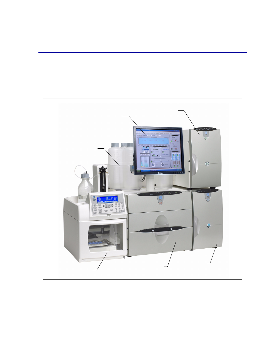
1.1 ICS-3000 System Overview
1 • Introduction
Chromeleon®/Chromeleon
Xpress Monitor
ICS-3000 Eluent
Organizer
AS Autosampler
ICS-3000 Dual
ICS-3000
Detector/Chromatography
Module
Pump
ICS-3000 Eluent
Generator
Figure 1-1. ICS-3000 System for Dual-Analysis RFIC
The Dionex ICS-3000 Ion Chromatography System offers a full range of Reagent-
™ IC (RFIC™) components. RFIC combines automated eluent generation
Free
and self-regenerating suppression to make IC easier and more powerful than ever
Doc. 065031-04 1/08 1
Page 18
ICS-3000 Ion Chromatography System
before. It is no longer necessary to spend time preparing eluents and regenerants.
All you need is deionized water—the IC system automatically generates eluent in
the exact amount and concentration needed for your application, ensuring superior
analytical results.
The dual-analysis capabilities (both simultaneous and sequential) of the ICS-3000
system let you maximize efficiency and throughput and minimize downtime. The
modular system design lets you quickly configure and customize hardware.
1.1.1 ICS-3000 System Components
The table below identifies modules in the ICS-3000 product line, as well
as additional products that can be added to an ICS-3000 system. Refer to
the page number indicated here for a brief product overview.
Product Type Product Name
Pump
Detector/Chromatography
Compartment
Detector (inside DC)
Accessory (inside DC)
Detector (outside DC)
Thermal Compartment
Eluent Generator
Eluent Organizer
ICS-3000 Dual Pump (see page 3)
ICS-3000 Single Pump (see page 3
ICS-3000 Detector/Chromatography
Module (see page 3
ICS-3000 Conductivity Detector (see
page 4
)
ICS-3000 Electrochemical Detector (see
page 4
)
ICS-3000 Automation Manager (see
page 4
)
ICS-Series Photodiode Array Detector (see
page 7
)
ICS-Series Variable Wavelength Detector
(see page 7
ICS-3000 Thermal Compartment (see
page 4
ICS-3000 Eluent Generator (see page 5)
ICS-3000 Eluent Organizer (see page 5)
)
)
)
)
2 Doc. 065031-04 1/08
Page 19

1 • Introduction
Autosampler
Mass Spectrometer
ICS-3000 Dual Pump (DP) and ICS-3000 Single Pump (SP)
AS Autosampler (see page 6)
AS40 Automated Sampler (see page 7
MSQ Plus™ (see page 8)
)
With flow rates ranging from 0.001 to 10.0 mL/min and operating
pressures up to 35 MPa (5000 psi), the DP/SP is designed for both
standard bore and microbore applications. The pump’s patented isokinetic
pre-compression phase allows a precise, almost pulse-free flow.
The SP contains one isocratic pump or one gradient pump. The DP
contains two gradient pumps, two isocratic pumps, or one isocratic pump
and one gradient pump.
The isocratic pump delivers one eluent, while the gradient pump can
deliver gradient mixtures of up to four eluent components. The selected
eluent composition can be delivered as isocratic, isocratic proportioned,
linear ramp, step, curved, or any combination of these.
With a DP, the second pump can be operated as a second-channel
chromatography pump, an auxiliary dependent pump, or an auxiliary
independent pump.
ICS-3000 Detector/Chromatography Module (DC)
The DC provides a temperature-controlled environment for ICS-3000
chromatography components. The DC can accommodate components for
two channels, plumbed either serially or in parallel.
The following components may be installed in the DC:
• Conductivity detector
• Electrochemical detector
• Injection valves
• Switching valves
• Guard and separator columns
• Suppressors
• ICS-3000 Automation Manager
Doc. 065031-04 1/08 3
Page 20

ICS-3000 Ion Chromatography System
ICS-3000 Conductivity Detector (CD)
The CD is a modular detector with integrated cell providing dual
detection capabilities (series or parallel). The CD has a signal range up to
15,000
The CD is installed in the upper compartment of the DC.
ICS-3000 Electrochemical Detector (ED)
The ED is a modular detector and cell with dual-detection capabilities
(series or parallel). The ED supports multiple waveforms, multiple
integration times, and post-analysis data manipulation. The ED is also
capable of providing 3D amperometry data. The ED cell can be
configured with gold, silver, platinum, or glassy carbon working
electrodes. The ED is installed in the upper compartment of the DC.
ICS-3000 Automation Manager (AM)
The AM consists of a component mounting panel on a base tray. The AM
provides mounting sites for sample preparation and post-column
application components: high-pressure (switching) valves, low-pressure
(solenoid) valves, reaction coils, etc. The AM is installed in the upper
compartment of the DC, above the detector.
μS and supports high background, nonsuppressed applications.
ICS-3000 Thermal Compartment (TC)
The TC provides a temperature-controlled environment for ICS-3000
chromatography components. The TC is intended for applications that do
not require conductivity or electrochemical detection.
The TC is available in four configurations:
• With one 2-position, 6-port high-pressure injection valve
• With two 2-position, 6-port high-pressure injection valves
• With one 2-position, 6-port high-pressure injection valve and one 2-
position, 10-port high-pressure injection valve
• With no injection valves
An optional temperature stabilizer (standard bore, P/N 064548;
microbore, P/N 064650) can be installed inside the TC, if necessary. The
temperature stabilizer brings the eluent to the column temperature before
it enters the column.
4 Doc. 065031-04 1/08
Page 21

1 • Introduction
ICS-3000 Eluent Generator (EG)
The EG generates high purity acid or base eluents online from deionized
water. The EG can be configured for single- or dual-channel operation.
Each channel includes:
• A high precision programmable current source (power supply)
• A high pressure gas removal device that removes electrolysis gases
created during eluent generation
The following options must be ordered separately for installation inside
the EG:
• A disposable EluGen® cartridge to generate eluent. Each cartridge
contains 900 mL of the appropriate electrolyte concentrate solution.
• A Continuously Regenerated Trap Column (CR-TC) to remove any
extraneous contaminants from the deionized water source. The CRTC is electrolytically-regenerated, which allows it to operate for
extended periods without chemical regeneration.
ICS-3000 Eluent Organizer (EO)
The EO holds eluent reservoirs in a liner that contains spills and leaks. Up
to two EOs can be installed on top of the DC. Each EO accommodates up
to four 1-liter or 2-liter reservoirs or up to two 4-liter reservoirs. The EO
is typically ordered configured with four 2-liter reservoirs (P/N 062629).
All eluent reservoirs available for use with the DP/SP can be pressurized.
If you plan to pressurize the eluent reservoirs, the optional EO Regulator
Accessory and Stand (P/N 063493) is required.
The Regulator Accessory includes a pressure regulator and gauge
assembly with four outputs (for connections to four eluent reservoirs), as
well as the tubing and connection fitting required. If more reservoirs are
required, order a second regulator (P/N 064387).
Doc. 065031-04 1/08 5
Page 22

ICS-3000 Ion Chromatography System
AS Autosampler (AS)
The AS is a powerful, full-featured autosampler that precisely delivers
from 1.0 to 99.9 µL (in 0.1 µL increments) or 100 to 1000 µL (in 1 µL
increments) of sample to an injection valve. The autosampler can operate
in several modes:
• Concentrate—Sample is delivered to a single analytical system for
trace analysis and matrix elimination; a concentrator column is
installed on the injection valve in place of a loop.
• Simultaneous—Sample is delivered to two analytical systems
simultaneously; a sample loop is installed on each injection valve.
Sample is delivered equally to the two systems (50% of the volume to
each), allowing two complete, separate analyses to be performed with
just one sample.
• Sequential—Sample is delivered to two analytical systems in
sequence. This allows on-demand injection of two independent
samples to two applications, using one autosampler. While the first
system is being analyzed, the second system is being prepped and
loaded for sample analysis.
• Sequential Concentrate—Sample is delivered to two analytical
systems in sequence; a concentrator column is installed on the
injection valve in place of a loop.
• Reagent Prime (available in Concentrate mode only)—Primes the
lines with reagent. For example, implementing the Reagent Prime
mode during the matrix elimination step ensures that the appropriate
reagent is in line for matrix elimination and prevents crosscontamination between reagents.
• Reagent Flush (available in Concentrate mode only)—Flushes the
concentrator column with reagent (for example, a known source of
clean deionized water) to remove unwanted sample matrix.
6 Doc. 065031-04 1/08
Page 23

1 • Introduction
AS40 Automated Sampler (AS40)
The AS40 is a low-cost, metal-free, sample loading device designed for
ion chromatography applications. The AS40 is capable of delivering
between 0.2 and 5.0 mL of sample in set increments. The AS40 holds
between 66 and 88 vials, depending upon the vial size in use: 0.5 mL,
5.0 mL, or a combination of both sizes. Up to three injections can be
taken from each vial.
The AS40 holds up to 11 cassettes of six 5-mL vials or eight 0.5-mL vials.
Each sample is filtered during loading through a 20-µm filter in the vial
cap, so there is no need to prefilter samples. Samples can be loaded
against backpressures up to 690 kPa (100 psi) without an external
sampling pump, thus facilitating preconcentration work.
ICS-Series Photodiode Array Detector (PDA)
The PDA optical detector is capable of measuring the absorbance
spectrum from 190 to 800 nm. A deuterium lamp optimizes the UV range
(190 to 380 nm) and a tungsten lamp optimizes the visible range (380 to
800 nm).
The PDA enables you to collect up to five single wavelengths (2D
chromatograms) without being required to collect 3D data. Collecting
individual wavelengths instead of the spectra offers two advantages: it
eliminates the need to perform extractions for analyses that do not require
spectral data and it conserves disk space.
ICS-Series Variable Wavelength Detector (VWD)
The VWD is a dual-beam, variable wavelength photometer with one
measurement and one internal reference beam. Spectral capability from
190 to 900 nm is provided by two light sources: a deuterium lamp for
ultraviolet detection and a tungsten lamp for visible wavelength
operation. The four-channel detector measures at up to four wavelengths
simultaneously. The VWD contains a built-in holmium oxide filter for
wavelength verification. To suppress higher-order radiation, two optical
filters can be inserted (automatically) into the light path.
Doc. 065031-04 1/08 7
Page 24

ICS-3000 Ion Chromatography System
MSQ Plus Mass Spectrometer
The MSQ Plus is an advanced analytical instrument that includes an MS
detector, vacuum pumps, and data system. When integrated with an IC
system, the MSQ Plus provides the separation capability of an IC and the
detection capability of a single-quadrupole MS detector. This provides a
strong starting point for sample analysis by offering a quick and clear
mass identification for chromatographic peaks.
The MS detector contains an atmospheric pressure ionization (API)
source, advanced high efficiency transmission ion optics of a square
quadrupole RF lens and dual RF generators, a mass analyzer, and an ion
detection system. An optional cone wash pump is available for improved
performance when dealing with dirty matrices.
The MS detector is equipped with FastLock™ probes for two
complementary ionization techniques: atmospheric pressure chemical
ionization (APCI) and electrospray ionization (ESI). Both ionization
techniques can be run in either the positive or negative ion polarity mode.
The design of the interchangeable probes enables rapid switching of
ionization modes.
During a scan, ions of selected mass-to-charge ratios are sequentially
transmitted through a quadrupole mass filter analyzer. The MS detector
has fully automatic mass scale calibration (15 to 2000 m/z) and tuning
that makes optimization simple and direct. The MS detector can perform
both full-range scans and selected ion monitoring (SIM) scans. When
operating in conjunction with Chromeleon, the MSQ Plus can be set up to
vary the scan type, the ionization technique, and the ion polarity mode.
8 Doc. 065031-04 1/08
Page 25
1.1.2 ICS-3000 System Control
The ICS-3000 system is controlled by a PC configured with Chromeleon
Chromatography Management System (version 6.7 or later) or
Chromeleon Xpress. The Chromeleon
System provides complete instrument control, data acquisition, and data
management. Chromeleon Xpress
monitoring of Dionex chromatography instruments, but does not
include data management capabilities.
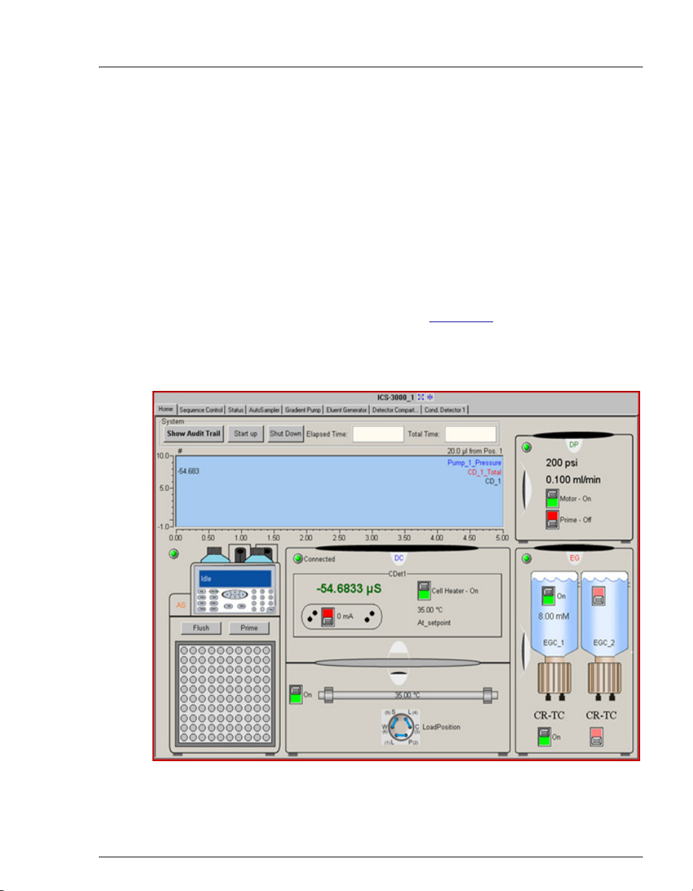
Chromeleon and Chromeleon Xpress provide a panel tabset that replaces
and combines the module front panels into one centralized system control
panel. A convenient Home panel (see Figure 1-2
system status. Individual tabs provide quick access to module functions,
as well as detailed status and diagnostics.
1 • Introduction
Chromatography Management
provides real-time control and
) shows the overall
Figure 1-2. ICS-3000 Panel Tabset (Home Panel Shown)
Doc. 065031-04 1/08 9
Page 26

ICS-3000 Ion Chromatography System
1.2 ICS-3000 System Documentation
Every effort has been made to provide complete and accurate user documentation
for the ICS-3000 system. The table below lists the primary sources of product
information and the formats in which information is available.
Source Part
Number
ICS-3000 Ion Chromatography System
Operator’s Manual
Installing the ICS-3000 Ion Chromatography
System
AS Autosampler Operator’s Manual 065051 Yes No
ICS-Series Photodiode Array Detector
Operator’s Manual
ICS-Series Variable Wavelength Detector
Operator’s Manual
Chromeleon Xpress Quick Reference Guide 065070 Yes No
Chromeleon Xpress online Help N/A N/A N/A
Chromeleon Software User’s Guide
Installing the Chromeleon Chromatography
Management System with a Dionex Ion
Chromatograph (IC)
Chromeleon online Help N/A N/A N/A
065031 Yes No
065032 Yes Yes
065147 Yes No
065141 Yes No
4829.5060
031883 Yes Yes
PDF
File
Ye s N o
Printed
Manual
All Adobe
® PDF files listed above are shipped on the Dionex Reference Library
CD-ROM (P/N 053891), which is included in the ship kit of each ICS-3000
system module. In addition, the software manuals are provided as PDF files on the
Chromeleon or Chromeleon Xpress CD-ROM.
A printed copy of the software installation instructions is provided in the software
ship kit.
Consumables documentation: For complete information about Dionex columns,
suppressors, EluGen cartridges, etc., refer to the appropriate product manual.
These manuals are provided on the Reference Library CD-ROM.
10 Doc. 065031-04 1/08
Page 27

1.3 The ICS-3000 System Operator’s Manual
1.3.1 Overview
The electronic version (i.e., PDF file) of the ICS-3000 system operator’s
manual contains numerous hypertext links that can take you to other
locations within the file. These links include:
• Table of contents entries
• Index entries
• Cross-references (underlined in blue) to sections, figures, tables, etc.
If you are not familiar with how to navigate PDF files, refer to the Help
system for Adob
e® Acrobat® or Adobe Reader® for assistance.
1 • Introduction
Chapter 1
Introduction
Chapter 2
Description
Chapter 3
System
Configurations
Chapter 4
Getting Started
Chapter 5
Operation
Chapter 6
Shutdown
Chapter 7
Maintenance
An overview of the ICS-3000 system; includes a
brief description of the ICS-3000 modules, the
software required for ICS-3000 operation, and the
ICS-3000 user manuals.
Detailed descriptions of ICS-3000 system
components and important operating features;
includes an introduction to Chromeleon and
Chromeleon Xpress software.
Detailed illustrations of component plumbing for
several different ICS-3000 system configurations.
Tasks to be performed before beginning operation
of the ICS-3000 system.
Instructions for routine operation of the ICS-3000
system with Chromeleon or Chromeleon Xpress
software.
Short-term and long-term shutdown procedures
for the ICS-3000 system.
Routine preventive maintenance procedures for
the ICS-3000 system.
Doc. 065031-04 1/08 11
Page 28
ICS-3000 Ion Chromatography System
Chapter 8
Troubleshooting
Minor problems that may occur during operation
of the ICS-3000 system, with step-by-step
procedures for how to isolate and eliminate the
cause of each problem. Includes a list of
Chromeleon and Chromeleon Xpress Audit Trail
error messages, with an explanation of the
possible cause of each message and the corrective
action to take.
Chapter 9
Service
Step-by-step instructions for routine service and
parts replacement procedures the user can
perform for the ICS-3000 system.
Appendix A
Specifications
Appendix B
Reordering
Information
Specifications and installation site requirements
for the ICS-3000 modules.
Spare parts for the ICS-3000 modules.
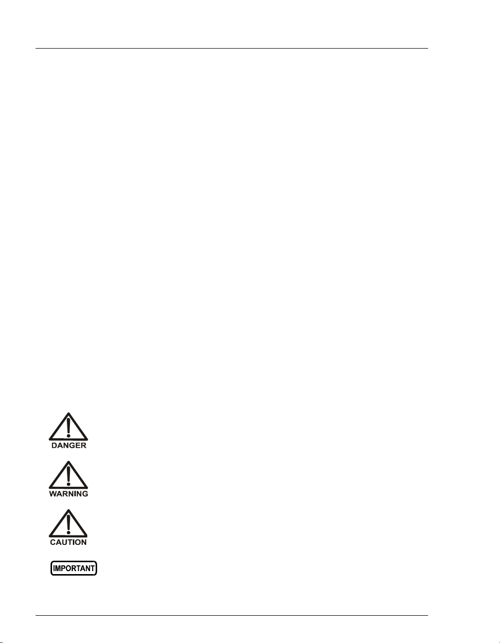
1.3.2 Safety Messages and Notes
This manual contains warnings and precautionary statements that can
prevent personal injury and/or damage to the ICS-3000 system when
properly followed. Safety messages appear in bold type and are
accompanied by icons, as shown below.
Indicates an imminently hazardous situation which, if not avoided, will
result in death or serious injury.
Indicates a potentially hazardous situation which, if not avoided,
could result in death or serious injury.
Indicates a potentially hazardous situation which, if not avoided, may
result in minor or moderate injury. Also used to identify a situation or
practice that may seriously damage the instrument, but will not cause
injury.
Indicates that the function or process of the instrument may be
impaired. Operation does not constitute a hazard.
12 Doc. 065031-04 1/08
Page 29
1 • Introduction
Messages d'avertissement en français
Signale une situation de danger immédiat qui, si elle n'est pas évitée,
entraînera des blessures graves à mortelles.
Signale une situation de danger potentiel qui, si elle n'est pas évitée,
pourrait entraîner des blessures graves à mortelles.
Signale une situation de danger potentiel qui, si elle n'est pas évitée,
pourrait entraîner des blessures mineures à modérées. Également
utilisé pour signaler une situation ou une pratique qui pourrait
gravement endommager l'instrument mais qui n'entraînera pas de
blessures.
Warnhinweise in Deutsch
Bedeutet unmittelbare Gefahr. Mißachtung kann zum Tod oder
schwerwiegenden Verletzungen führen.
Bedeutet eine mögliche Gefährdung. Mißachtung kann zum Tod oder
schwerwiegenden Verletzungen führen.
Bedeutet eine mögliche Gefährdung. Mißachtung kann zu kleineren
oder mittelschweren Verletzungen führen. Wird auch verwendet, wenn
eine Situation zu schweren Schäden am Gerät führen kann, jedoch
keine Verletzungsgefahr besteht.
Doc. 065031-04 1/08 13
Page 30

ICS-3000 Ion Chromatography System
Notes
Informational messages also appear throughout this manual. These are
labeled NOTE and are in bold type:
NOTE NOTES call attention to certain information. They
alert you to an unexpected result of an action,
suggest how to optimize instrument performance,
etc.
1.4 Safety and Regulatory Information
The ICS-3000 system is designed for IC (ion chromatography) and HPLC (highperformance liquid chromatography) applications and should not be used for any
other purpose. Operation of an ICS-3000 module in a manner not specified by
Dionex may result in personal injury.
1.4.1 Safety Labels
The TUV GS, C, US Mark safety label and the CE Mark label on the ICS3000 modules indicate that they are in compliance with the following
standards:
EMC Susceptibility and Immunity
• (DC, EG, DP, SP) EN 61326 1997 including A1:1998 and A2:2001
• (TC) EN 61326 1997 including A1:1998, A2:2001, and A3:2003
Safety
• (DC, EG, DP, SP) EN 61010-1:2001, UL 61010-1:2004, CAN/CSA-
C22.2 61010-1:2004
• (TC) EN 61010-1:2001, UL 61010A:2002, CAN/CSA-C22.2 61010-
1:2004
NOTE The TC does not carry the TUV GS Mark safety
label.
14 Doc. 065031-04 1/08
Page 31

1 • Introduction
These symbols appear on the ICS-3000 modules or on labels affixed to
the modules:
Alternating current
˜
Protective conductor terminal
Power supply is on
Power supply is off
Indicates a potential hazard. Refer to this operator’s manual
for an explanation of the hazard and how to proceed.
Doc. 065031-04 1/08 15
Page 32

ICS-3000 Ion Chromatography System
16 Doc. 065031-04 1/08
Page 33

DP/SP Description
2.1 DP/SP Front Features
A status bar on the front of the ICS-3000 Dual Pump (DP) and ICS-3000 Single
Pump (SP) includes buttons for controlling certain pump functions, as well as
LEDs (light emitting diodes) that indicate the status of several pump functions
(see Figure 2-1
and Figure 2-2).
2 • Description
CONNECTED
CONNECTED
ALARM
ALARM
FLOW PRIME
PUMP 1 PUMP 2
FLOW PRIME
Figure 2-1. DP Status Bar
PRIME
FLOW
PUMP 1
Figure 2-2. SP Status Bar
Doc. 065031-04 1/08 17
Page 34

ICS-3000 Ion Chromatography System
Button/LED Label If the LED Is On If the LED Is Flashing
CONNECTED
The DP/SP is connected to a
Chromeleon or Chromeleon
Xpress timebase.
Does not flash.
ALARM
A DP/SP-related problem has
Does not flash.
occurred (for example, a
pressure limit was activated).
Check the Chromeleon or
Chromeleon Xpress Audit
Trail for the cause.
PUMP 1 FLOW*
PUMP 2 FLOW**
PUMP 1 PRIME*
PUMP 2 PRIME**
The DP/SP is on and is
delivering flow.
Use the
PRIME button to
prime the pump.
Does not flash.
The pump is being primed.
The LED indicates whether
the pump is being primed.
POWER
Use this POWER button for
Does not flash.
routine on/off control of the
DP/SP. When the power is on,
this LED is lighted. To turn off
the DP/SP, press and hold this
POWER button for 2 seconds.
Note: The main power switch
is on the rear panel.
* Pump 1 is always installed in the lower half of the DP/SP enclosure.
** SP only: This button is not present.
18 Doc. 065031-04 1/08
Page 35

2.2 DP/SP Interior Components
The pump’s mechanical components are located directly behind the front door of
the module. Figure 2-3
both a gradient pump (pump 1) and an isocratic pump (pump 2).
For servicing components, the component mounting panel slides out about 5 cm
(2 in) for easy access to components. To pull the panel out, use the handles on the
top and bottom of the panel.
1
3
2
4
10
5
shows the mechanical components of a DP that contains
7
6
8
9
12
11
2 • DP/SP Description
Status Bar
1
Secondary Pump Head
2
Priming Valve
3
Pressure Transducer
4
Primary Pump Head
5
Peristaltic Pump (for
6
seal wash system)
Vacuum Degas Chamber
7
(one channel)
Eluent Supply On/Off Valve
8
Tubing Chase (Pump 2)
9
Handle
10
Piston Seal Wash Reservoir
11
Vacuum Degas Chambers
12
(four channels)
Static Mixer
13
Proportioning Valve Fittings
14
Tubing Chase (Pump 1)
15
Leak Sensor
16
10
13
16
14
15
Figure 2-3. DP/SP Interior Components (DP Shown)
Doc. 065031-04 1/08 19
Page 36

ICS-3000 Ion Chromatography System
2.2.1 Pump Heads
The DP/SP is a zero-pulsation, serial dual-piston pump with electronic
compressibility compensation. Two pump heads—a primary head and a
secondary head—are connected in series. Eluent passes through both
pump heads in succession.
The primary pump head delivers eluent at the selected flow rate, while
simultaneously filling the secondary pump head. The latter serves as a
reservoir and delivers eluent while the primary head carries out the refill
stroke.
The characteristic feature of the patented isokinetic pre-compression
phase is the programmed overlapping of the delivery strokes of the two
pump heads. When delivering compressible liquids without controlled
pre-compression, the pulsation increases as the operating pressure
increases, since part of the delivery stroke is required to compress eluent
in the pump head.
During the pre-compression phase, pulsation is minimized by velocity
modulation of the drive. A patented secondary control system (automatic
compressibility compensation) ensures highly constant eluent delivery.
The flow rate remains constant in relation to the pressure.
2.2.2 Pressure Transducer
The secondary pump head contains a built-in pressure transducer to
measure the system pressure. The DP/SP Moduleware (the instrument
control firmware installed in the pump) precisely controls the pump motor
speed to ensure flow rate accuracy and to maintain constant flow and
constant pressure.
Flow output from the secondary pump head passes through a static mixer
(described in Section 2.2.6
chromatography system (the injection valve, columns, and detector).
) before being directed to the remainder of the
2.2.3 Proportioning Valves (Gradient pump only)
In the gradient pump, eluent flows from the eluent reservoirs, through the
vacuum degas chambers, and into a four-way proportioning valve
assembly (see Figure 2-3
proportioned by the four valves.
20 Doc. 065031-04 1/08
). Programmed percentages of each eluent are
Page 37

2.2.4 Vacuum Degassing Module
The DP/SP vacuum degassing module provides continuous, online eluent
degassing. Eluent quality significantly affects DP/SP performance, and
vacuum degassing eluents is one way to ensure high eluent quality.
Degassing helps prevent bubbles (caused by eluent outgassing) from
forming in the eluent proportioning valves (gradient pump only), pump
heads, and detector cell. Degassing eluents is especially important when
combining aqueous and nonaqueous components (for example, water and
acetonitrile).
The vacuum degassing module is either single-channel (in an isocratic
pump) or quad-channel (in a gradient pump). The module consists of:
• A degas chamber (with degassing membranes) with internal capacity
of 670
μL per channel
• A dual-stage diaphragm vacuum pump
• An on-board vacuum sensor
• The electronics required to operate the vacuum pump
2 • DP/SP Description
• Tubing, fittings, and other accessories
The vacuum degassing module is automatically activated when the DP/SP
power is turned on. Allow about 10 minutes for the module to equilibrate.
NOTE Make sure the run time is long enough to ensure
that the vacuum degassing module delivers the
optimal degassing performance.
Manual Control of the Vacuum Degassing Module
The vacuum degassing module normally remains on continuously. To turn
it off (for example, to investigate a leak), follow these steps:
1. In Chromeleon or Chromeleon Xpress, select Command on the
Control menu or press the F8 key.
2. In the Commands dialog box, select the pump name.
3. Select the Degasser command.
4. Select Off and click the Execute button.
5. To turn on the degasser again, select On and click Execute.
Doc. 065031-04 1/08 21
Page 38

ICS-3000 Ion Chromatography System
2.2.5 Piston Seal Wash System
The piston seal wash system consists of a peristaltic pump, a reservoir
containing wash solution, and the connecting tubing. The wash solution is
usually ASTM Type I (18 megohm-cm) filtered and deionized water.
When seal washing is activated, the back of the main piston seal is rinsed
with wash solution; this prolongs seal lifetime by preventing eluent
crystallization on the seal surfaces.
Notes About the DP Piston Seal Wash System
The piston seal wash system is designed for use with only one of the two
pumps in a DP module. When the DP is shipped from Dionex, the seal
wash system is connected to pump 1 (the bottom pump). If necessary,
connect the seal wash system to pump 2 (the top pump), instead. For
instructions on how to replumb the system, refer to Section 4.5
NOTE Dionex offers an External Seal Wash Kit
(P/N 063518) for users who need to operate a piston
seal wash system for both pumps in the DP.
Installation instructions are provided in the kit.
.
2.2.6 Static Mixer
A GM-3 or GM-4 static mixer is installed after the secondary pump head
(see Figure 2-3
proportioned eluents are mixed thoroughly. In the isocratic pump, the
mixer is optional, but can function as a pulse damper.
The DP/SP gradient delay volume is 600
μL when a GM-4 is installed. The gradient delay volume (or dwell
380
volume) is the volume of liquid in the system between the point where the
gradient is formed and the point where it enters the column. This includes
the mixer, transfer tubing, and swept volume in the injector or
autosampler.
22 Doc. 065031-04 1/08
). In the gradient pump, the mixer helps to ensure that
μL when a GM-3 is installed and
Page 39

2.3 DP/SP Flow Schematics
ON/O
E
2.3.1 Isocratic Pump Flow Schematic
Figure 2-4 illustrates the liquid flow path through an isocratic pump.
2 • DP/SP Description
TO INJECTION VALV
ELUENT
OUTLET
CHECK VALVE
VACUUM
DEGAS
ELUENT SUPPLY
FF VALVE
PUMP
HEAD
PUMP
HEAD
INLET
CHECK VALVE
Figure 2-4. Isocratic Pump Flow Schematic
• Eluent flows from the reservoir, through the vacuum degas chamber
(if the vacuum degas module is installed), through the eluent supply
on/off valve, and into the inlet check valve on the primary pump head.
• The inlet check valve opens, drawing eluent into the primary pump
head. At the same time, the secondary piston pushes forward, pushing
eluent into the system. After completing the intake, the primary
piston pushes eluent through the outlet check valve and into the
secondary pump head.
• Flow exits the secondary pump head and is directed to the remainder
of the chromatography system (the injection valve, columns, and
detector).
Doc. 065031-04 1/08 23
Page 40

ICS-3000 Ion Chromatography System
E
2.3.2 Gradient Pump Flow Schematic
Figure 2-5 illustrates the liquid flow path through a gradient pump.
ELUENT
D
ELUENT
C
ELUENT
B
ELUENT
A
STATIC
MIXER
TO INJECTION VALV
OUTLET
CHECK VALVE
VACUUM
DEGAS
PROPORTIONING
VALV E
PUMP
HEAD
D
C
A
B
PUMP
HEAD
INLET
CHECK VALVE
Figure 2-5. Gradient Pump Flow Schematic
• Eluent flows from the reservoirs and through the vacuum degas
chambers. The selected proportions of eluent flow out of the
proportioning valve assembly and into the inlet check valve on the
primary pump head.
• The inlet check valve opens, drawing eluent into the primary pump
head. At the same time, the secondary piston pushes forward, pushing
eluent into the system. After completing the intake, the primary
piston pushes eluent through the outlet check valve and into the
secondary pump head.
• Flow exits the secondary pump head, continues through the static
mixer, and is then directed to the remainder of the chromatography
system (the injection valve, columns, and detector).
24 Doc. 065031-04 1/08
Page 41

2.4 DP/SP Rear Panel
Figure 2-6 illustrates the rear panel of the DP/SP.
1
1
2
4
7
2 • DP/SP Description
Tubing Chase (2)
1
Main Power Switch, Fuse Holder,
3
2
and Power Receptacle
Analog Pressure Output
3
5
Digital I/O Port
4
6
USB Receptacle
5
(“B” Connectors)
USB Ports (3)
6
(“A” Connectors)
Exhaust Port from Vacuum
7
Degas Module
Waste Line from
8
Drip Tray
8
Figure 2-6. DP/SP Rear Panel
Tubing Chases
The tubing chases route tubing from the front of the DP/SP, through the interior of
the module, and to the rear panel.
Main Power Switch, Fuse Holder, and Power Receptacle
The rear panel power switch is the main power switch for the DP/SP. Turn on the
main power switch before initial operation and leave it on unless instructed to turn
it off (for example, before performing a service procedure).
NOTE For routine on/off control, use the POWER button on the
front of the DP/SP (see Figure 2-1
and Figure 2-2). To
Doc. 065031-04 1/08 25
Page 42

ICS-3000 Ion Chromatography System
turn off the pump, press and hold the POWER button for
2 seconds.
The fuse cartridge contains two 2-amp IEC 60127-2 slow-blow fuses
(P/N 954773). For instructions on how to change the fuses, see Section 9.9
The power cord plugs into the IEC 320 three-prong receptacle.
The power supply cord is used as the main disconnect device. Make
sure the socket-outlet is located near the DC and is easily accessible.
Le cordon d'alimentation principal est utilisé comme dispositif
principal de débranchement. Veillez à ce que la prise de base soit
située/installée près du module et facilement accessible.
Das Netzkabel ist das wichtigste Mittel zur Stromunterbrechung.
Stellen Sie sicher, daß sich die Steckdose nahe am Gerät befindet und
leicht zugänglich ist.
Digital I/O Port
The digital I/O port provides a connection to an AS40 Automated Sampler or
other auxiliary device. The connector includes three TTL inputs and four relay
outputs. Table 2-1
indicates the functions assigned to the connector pins.
.
For instructions on connecting the pump to an AS40, refer to the ICS-3000 Ion
Chromatography System Installation Instructions (Document No. 065032). The
manual is included on the Dionex Reference Library CD-ROM (P/N 053891).
The maximum switching voltage of the relays is 24 V. The switching
current must not exceed 100 mA.
Pin Number Signal Name Signal Level Description
1 ----- ----- Not used
2 ----- ----- Not used
3 Relay 3 Out Potential-free Normally open
4 Relay 1 Out Potential-free Normally closed
5 Relay 2 Out Potential-free Normally closed
6 Relay 3 Out Potential-free Normally closed
Table 2-1. 25-Pin D-Sub I/O Port (Female)
26 Doc. 065031-04 1/08
Page 43

2 • DP/SP Description
Pin Number Signal Name Signal Level Description
7 Relay 1 Out Potential-free Common
8 Relay 2 Out Potential-free Common
9 Gnd Ground Ground
10 Gnd Ground Ground
11 Gnd Ground Ground
12 Gnd Ground Ground
13 ----- ----- Not used
14 Relay 4 Out Potential-free Normally open
15 Relay 4 Out Potential-free Common
16 Relay 4 Out Potential-free Normally closed
17 ----- ----- Not used
18 Relay 3 Out Potential-free Common
19 Relay 1 Out Potential-free Normally open
20 Relay 2 Out Potential-free Normally open
21 Vcc Out +5V +5V, 500 mA
22 TTL Input 1 TTL Hold/Run
23 TTL Input 2 TTL Stop
24 TTL Input 3 TTL Start
25 ----- ----- Not used
Table 2-1. 25-Pin D-Sub I/O Port (Female) (Continued)
Analog Pressure Output
The analog pressure output indicates the operating pressure of the pump. The
pressure output is set to 50 mV/MPa (5 mV/14.51 psi). To monitor the pressure,
connect the pressure output to a recorder or an A/D converter. These are the pin
assignments for the 2-pin Cinch connector (P/N 8005.9001A):
Signal Level Function
Inner ring: Signal (pressure)
Outer ring: Ground
Doc. 065031-04 1/08 27
Page 44

ICS-3000 Ion Chromatography System
The analog pressure output defaults to the pump 1 (bottom pump) output signal.
To redirect the output to pump 2 (the top pump), follow these steps:
1. In Chromeleon or Chromeleon Xpress, select Command on the Control
menu or press the F8 key.
2. In the Commands dialog box, select the pump name.
3. Select the AnalogOut command.
4. Select PumpTop in the AnalogOut drop-down box and click Execute.
USB Connections
• One USB receptacle (“B” type connector) allows a connection from the PC on
which Chromeleon or Chromeleon Xpress software is installed.
• Three USB (Universal Serial Bus) ports (“A” type connectors) are provided
for connections to other ICS-3000 modules.
One 1.8-m (6-ft) USB cable (P/N 960777) is provided in the ship kit (DP Ship Kit,
P/N 062463; SP Ship Kit, P/N 063342).
Waste Lines
• One waste line is connected to the secondary pump head.
• One waste line exits the drip tray and is routed to the rear panel.
Place the free ends of the waste lines into one waste container. To maintain a
positive siphon, position the waste container below the level of the pump.
NOTE To ensure proper drainage, the waste lines must remain
above the liquid level in the waste container.
28 Doc. 065031-04 1/08
Page 45

2.5 Eluent Reservoirs
The following reservoirs are available for use with the DP/SP:
• 1-liter plastic reservoir (P/N 063291)
• 2-liter plastic reservoir (P/N 062510)
• 4-liter plastic reservoir (P/N 063292)
Do not use the 2-liter plastic reservoir (P/N 062510) for offline vacuum
degassing of eluents. The reservoir was not designed for this
purpose.
N'utilisez pas le réservoir en plastique de 2 litres (N/P 062510) pour le
dégazage à vide hors ligne d'éluants. Le réservoir n'a pas été conçu à
cette fin.
Verwenden Sie den 2-Liter Plastikbehälter (Bestell-Nr. 062510) nicht
zum Offline Vakkum-Entgasen von Eluenten. Der Behälter ist dafür
nicht ausgelegt.
2 • DP/SP Description
All eluent reservoirs listed above are pressurizable. Although the DP/SP does not
require pressurized reservoirs, Dionex recommends pressurizing reservoirs with
helium or nitrogen under the following circumstances:
• When using eluents that are sensitive to contamination.
• When combining aqueous and nonaqueous components (for example, water
and acetonitrile). Pressurizable reservoirs allow eluents to be stored under a
specific atmosphere.
Never pressurize eluent reservoirs above 0.07 MPa (10 psi).
Pressurizing reservoirs above this limit can cause the reservoir to
explode.
Ne mettez jamais les réservoirs d'éluants sous une pression
supérieure à 0,07 MPa (10 psi).
Doc. 065031-04 1/08 29
Page 46

ICS-3000 Ion Chromatography System
Setzen Sie den Eluentbehälter auf keinen Fall einem Druck über
0,07 MPa aus.
2.6 EO (Optional)
The ICS-3000 Eluent Organizer (EO) holds eluent reservoirs in a liner that
contains spills and leaks. Up to two EOs can be installed on top of the DC. Each
EO accommodates up to four 1-liter or 2-liter reservoirs or up to two 4-liter
reservoirs. The EO is typically ordered configured with four 2-liter reservoirs
(P/N 062629).
All eluent reservoirs available for use with the DP/SP can be pressurized. If you
plan to pressurize the eluent reservoirs, an optional regulator kit is required. The
kit is available in two versions:
• When the DC is installed as the topmost module in the system, the EO
Regulator Kit (P/N 063493) is required. The kit includes a pressure regulator
and gauge assembly with four outputs (for connections to four eluent
reservoirs), as well as the tubing and connection fitting required.
• When the TC, ICS-Series Variable Wavelength Detector, or ICS-Series
Photodiode Array Detector is installed as the topmost module in the system,
the TC/VWD/PDA Regulator Bracket Kit (P/N 064792) is required. The kit
includes the EO Regulator Kit described above, as well as a right-angle
regulator bracket and mounting hardware. After attaching the bracket to the
TC or detector, you will mount the gas regulator assembly on the bracket.
If more reservoirs are required, order a second regulator (P/N 062345).
30 Doc. 065031-04 1/08
Page 47

EG Description
2.7 EG Front Features
The status bar on the front of the ICS-3000 Eluent Generator (EG) includes
buttons that provide control of certain EG functions, as well as LEDs that indicate
the status of several EG functions (see Figure 2-7
).
CONNECTED
Button/LED
Label
CONNECTED
ALARM
EGC 1
EGC 2
CR-TC 1
CR-TC 2
12
CR-TC
ALARM
12
EGC
Figure 2-7. EG Status Bar
If the LED Is On Comment
The EG is connected to a Chromeleon
-----
or Chromeleon Xpress timebase.
An EG-related problem has occurred
(for example, the EluGen cartridge
was disconnected).
The EluGen cartridge is on and is
generating eluent.
Check the Chromeleon or
Chromeleon Xpress Audit
Trail for the cause.
EGC 1 is always installed in
the left section of the
component compartment.
EGC 2, if present, is installed
in the right section of the
compartment.
The CR-TC is on. CR-TC 1 is always installed in
the left section of the
component compartment.
CR-TC 2, if present, is
installed in the right section of
the compartment.
Doc. 065031-04 1/08 31
Page 48

ICS-3000 Ion Chromatography System
Button/LED
Label
POWER
If the LED Is On Comment
Use this POWER button for routine
on/off control of the EG. When the
power is on, this LED is lighted. To
turn off the EG, press and hold this
POWER button for 2 seconds.
NOTE: The EG status bar LEDs do not flash.
The main power switch is on
the EG rear panel.
32 Doc. 065031-04 1/08
Page 49

2.8 EG Interior Components
Figure 2-8 shows the EG component compartment, which is located directly
behind the front door. The component mounting panel divides the compartment
into two sections. In a single-channel EG, components are installed in the left
section only.
To access components for maintenance or service procedures, push down on the
slide release latch and pull the tray forward until it reaches the stop.
1
2
2 • EG Description
EluGen Cartridge
1
RFIC Eluent Degasser
3
2
Electrical Connectors
3
CR-TC
4
Waste Line
5
Drip Tray
6
Slide Release Latch
7
4
5
6
7
Figure 2-8. EG Interior Components
(Second (Right Side) Channel of a Dual-System EG Shown)
Doc. 065031-04 1/08 33
Page 50

ICS-3000 Ion Chromatography System
EluGen Cartridge
Several types of EluGen cartridges are available for use with the EG (see the table
below). Each cartridge contains 900 mL of the appropriate electrolyte concentrate
solution for eluent generation.
EluGen Cartridge Part Number Function
EGC II K2CO3
EluGen Cartridge
058904 Generates potassium carbonate eluent
for anion exchange separations.
Note: Produces a carbonate/bicarbonate
mixture when installed with the EPM
Electrolytic pH Modifier (P/N 063175)
EGC II KOH
EluGen Cartridge
EGC II LiOH
EluGen Cartridge
EGC II MSA
EluGen Cartridge
EGC II NaOH
EluGen Cartridge
and EGC-CO
058900 Generates potassium hydroxide eluent
for anion exchange separations.
058906 Generates lithium hydroxide eluent for
anion exchange separations.
058902 Generates methanesulfonic acid eluent
for cation exchange separations.
058908 Generates sodium hydroxide eluent for
anion exchange separations.
Mixer (P/N 061686).
3
For more information, refer to the EluGen cartridge manual. The manual is
included on the Dionex Reference Library CD-ROM (P/N 053891).
RFIC Eluent Degasser
The RFIC Eluent Degasser (P/N 062137) contains a tubing assembly that purges
the electrolysis gas from the freshly-generated eluent before it is directed to the
separator column.
Backpressure Coil (Optional)
The EluGen cartridge requires at least 14 MPa (2000 psi) of system backpressure
for removal of electrolysis gas from the eluent produced by the cartridge. A
system backpressure of 16 MPa (2300 psi) is ideal.
If necessary, increase the system backpressure by installing a backpressure coil
between the injection valve and the EluGen cartridge
refer to Section 9.15
34 Doc. 065031-04 1/08
.
OUTLET port. For details,
Page 51

2 • EG Description
Continuously Regenerated Trap Column (CR-TC)
The CR-TC is a high pressure, electrolytically-regenerated trap column. The CRTC is designed to remove anionic or cationic contaminants in the eluent or
deionized water and to reduce drift during gradient separations. Two versions of
the CR-TC can be used with the EG:
• CR-ATC (Continuously Regenerated Anion Trap Column, P/N 060477)
• CR-CTC (Continuously Regenerated Cation Trap Column, P/N 060478)
For more information, refer to the CR-TC manual. The manual is included on the
Dionex Reference Library CD-ROM (P/N 053891).
NOTE Do not install a CR-TC in the same channel as an EGC
K
Modifier.
EluGen Cartridge or an EPM Electrolytic pH
2CO3
NOTE The IonPac
IonPac CTC-1 Trap Column (P/N 040192) may be used
with the EG. However, both IonPac trap columns
require off-line chemical regeneration. Contact Dionex
for more information.
EPM Electrolytic pH Modifier and EGC-CO
® ATC-HC Trap Column (P/N 059604) or
Mixer
3
The EGC II K2CO3 EluGen Cartridge can be used with an EPM Electrolytic pH
Modifier (P/N 063175) and an EGC-CO
Mixer (P/N 061686) to produce a
3
carbonate/bicarbonate mixture for use with anion exchange separations on
carbonate-based IonPac columns.
After the cartridge generates potassium carbonate eluent, the EPM adjusts the
eluent concentration to produce the carbonate/bicarbonate mixture. The EGC-
Mixer provides mixing necessary to produce a homogenous solution of
CO
3
electrolytically-generated K
and KHCO3 eluent.
2CO3
For more information about these products, refer to the EluGen cartridge manual.
Cartridge manuals are included on the Dionex Reference Library CD-ROM
(P/N 053891).
Leak Sensor
If liquid collects in the drip tray in the bottom of the EG, a leak sensor reports the
leak to Chromeleon or Chromeleon Xpress, and an error message is displayed in
the Audit Trail. In addition, the
Alarm LED on the EG front panel lights.
Doc. 065031-04 1/08 35
Page 52

ICS-3000 Ion Chromatography System
Electrical Connections
Electrical connectors provide a connection from the components installed in the
EG to the EG power supplies. There are two sets of electrical connectors (one per
channel). Connections for the following components are provided:
• Two EluGen cartridges or one cartridge and one EPM Electrolytic pH
Modifier
and
• Two Continuously Regenerated Trap Columns (CR-TC)
When operating with an EGC II K
EluGen Cartridge and the EPM, the
2CO3
cartridge is connected to the EGC power supply for one channel and the EPM is
connected to the EGC power supply for the second channel. Thus, the EG can
accommodate only one such configuration.
Waste Line
The module waste line (white tubing) discharges liquid and gas waste from the
RFIC Eluent Degasser. This line is marked
WASTE-GAS SEPARATOR inside the
EG.
NOTE A gas separator waste tube (P/N 045460) should be
connected to the EG waste line during installation. For
details, refer to the ICS-3000 Ion Chromatography
System Installation Instructions (Document No. 065032).
Place the free end of the waste line into a waste container. To maintain an active
drain, position the waste container below the level of the EG.
NOTE To ensure proper drainage, each waste line must remain
above the liquid level in the waste container.
36 Doc. 065031-04 1/08
Page 53

2.9 EG Rear Panel
Figure 2-9 illustrates the rear panel of the ICS-3000 Eluent Generator (EG).
2 • EG Description
1
2
3
4
5
6
8
7
Exhaust Fan
1
Gas Vent Lines
2
USB Receptacle
3
(“B” Connector)
USB Ports (2)
4
(“A” Connectors)
Fuse Holder, Main Power
5
Switch, and Power
Receptacle
Tubing for Connecting to
6
Suppressors
Tub ing C hase
7
Drain Port from Drip Tray
8
Figure 2-9. EG Rear Panel
Exhaust Fan
The exhaust fan cools the interior of the EG and exhausts any hydrogen and
oxygen gases that escape during operation.
USB Connections
• One USB receptacle (“B” type connector) allows a connection from the PC on
which Chromeleon or Chromeleon Xpress software is installed.
• Two USB (Universal Serial Bus) ports (“A” type connectors) are provided for
connections to other ICS-3000 modules.
One 1.8-m (6-ft) USB cable (P/N 960777) is provided in the EG Ship Kit
(P/N 062453).
Doc. 065031-04 1/08 37
Page 54

ICS-3000 Ion Chromatography System
Fuse Holder, Main Power Switch, and Power Receptacle
The fuse cartridge contains two 2-amp slow-blow fuses (P/N 954773). For
instructions on how to change the fuses, see Section 9.16
The rear panel power switch is the main power switch for the EG. Turn on the
main power switch before initial operation and leave it on unless instructed to turn
it off (for example, before performing a service procedure).
NOTE For routine on/off control, use the POWER button on the
front of the EG (see Figure 2-7
press and hold the
The power cord plugs into the IEC 320 three-prong receptacle.
The power supply cord is used as the main disconnect device. Make
sure the socket-outlet is located near the EG and is easily accessible.
Le cordon d'alimentation principal est utilisé comme dispositif
principal de débranchement. Veillez à ce que la prise de base soit
située/installée près du module et facilement accessible.
Das Netzkabel ist das wichtigste Mittel zur Stromunterbrechung.
Stellen Sie sicher, daß sich die Steckdose nahe am Gerät befindet und
leicht zugänglich ist.
POWER button for 2 seconds.
.
). To turn off the EG,
Tubing Chase
The tubing chase routes tubing from the front of the EG, through the interior of
the module, and to the rear panel.
Vent, Suppressor, and Drain Lines
• The gas vent line (clear tubing) discharges the electrolysis gas (H
or O2) that
2
is vented from the electrolyte reservoir of the EluGen cartridge.
• The lines exiting the tubing chase (white tubing) are for connecting the
REGEN IN port on the CR-TC or EPM Electrolytic pH Modifier to the REGEN
OUT port on the suppressor.
• The drip tray drain port removes any liquid that collects in the drip tray in the
bottom of the EG. A clear corrugated tubing line is connected to this port
during installation.
38 Doc. 065031-04 1/08
Page 55

Place the free ends of the vent and drain lines into a waste container. To maintain
a positive siphon, position the waste container below the level of the EG.
NOTE To ensure proper drainage, each waste line must remain
above the liquid level in the waste container.
2.10 EG Flow Schematic
Figure 2-10 illustrates the liquid flow path through the EG.
Deionized water is delivered by the DP/SP to the EluGen cartridge. DC current is
applied to the cartridge to produce eluent.
The electrolytically-generated eluent flows through the Continuously Regenerated
Trap Column (CR-TC) into the RFIC Eluent Degasser, through the backpressure
coil (if installed), through the injection valve to the separator column, and finally
to the detector cell.
The detector cell effluent is directed through the Atlas or SRS suppressor
regenerant chamber to the CR-TC regenerant chamber, through the RFIC Eluent
Degasser inside the EG, and finally to waste.
2 • EG Description
NOTE Refer to the EGC-CO3 Mixer manual for a flow
schematic showing the components required to generate
a carbonate/bicarbonate mixture. The manual is
included on the Dionex Reference Library CD-ROM
(P/N 053891).
Doc. 065031-04 1/08 39
Page 56

ICS-3000 Ion Chromatography System
EGC VENT
To Waste
From pump
To injection valve port P
To gas separator waste tube
From suppressor REGEN OUT
Inlet
EGC
EGC
IN
EGC
OUT
Outlet
Eluent In Port
(red label)
Eluent
Out
Regen Out Port
Regen In Port
(orange label )
RFIC
Eluent
Degasser
Regen
Out
(blue label )
Regen Out
Regen In
Regen
In
Eluent
In
CR-TC
Eluent Out Port
(yellow label)
Figure 2-10. EG Flow Schematic Example
40 Doc. 065031-04 1/08
Page 57

DC Description
2.11 DC Front Features
A status bar on the front of the ICS-3000 Detector/Chromatography Module (DC)
(see Figure 2-12
LEDs that indicate the status of several DC components and functions.
) includes buttons for controlling certain DC functions, as well as
CONNECTED
12UPPER
ALARM
SUPPRESSOR OVEN VALVE 1 VALVE 2
LOWER LOAD INJECT LOAD INJECT
Figure 2-11. DC Status Bar
Button/LED Label If the LED Is On If the LED Is Flashing
CONNECTED
The DC is connected to a
Does not flash.
Chromeleon or Chromeleon Xpress
timebase.
ALARM
The leak sensor is wet or there was a
Does not flash.
valve or suppressor error. Check the
Chromeleon or Chromeleon Xpress
Audit Trail for the cause.
SUPPRESSOR 1
SUPPRESSOR 2
OVEN UPPER
The suppressor is on and current is
being applied.
The upper compartment is at its set
temperature.
Does not flash.
The upper compartment is
transitioning to the set
temperature. The
compartment is not ready for
operation.
OVEN LOWER
The lower compartment is at its set
temperature.
The lower compartment is
transitioning to the set
temperature. The
compartment is not ready for
operation.
Doc. 065031-04 1/08 41
Page 58

ICS-3000 Ion Chromatography System
Button/LED Label If the LED Is On If the LED Is Flashing
VALVE 1 LOAD
VALVE 2 LOAD
VALVE 1 INJECT
VALVE 2 INJECT
POWER
Use the VALVE 1 and VALV E 2
buttons to manually switch the
Valve error. See Section 8.25
for troubleshooting.
position of the DC injection valves.
The LEDs indicate whether the
valve is in the Load or Inject
position.
Use this POWER button for routine
Does not flash.
on/off control of the DC. When the
power is on, this LED is lighted. To
turn off the DC, press and hold this
POWER button for 2 seconds.
Note: The main power switch is on
the DC rear panel.
NOTE The VALVE 1 and VALVE 2 buttons can be enabled
and disabled in Chromeleon or Chromeleon Xpress.
When disabled, the valve can be controlled only
from the software. To enable or disable a button,
open the Commands dialog box (press F8) and select
the Valve1Button (or Valve2Button) command in
the list of commands for the DC.
42 Doc. 065031-04 1/08
Page 59

2 • DC Description
Sample Loading Ports
The front of the DC has two sample loading ports (see Figure 2-12) that can be
connected to injection valves installed inside the DC. A syringe is used to
manually load sample through the ports. For automated sample injection, the DC
can be connected to an autosampler. For more information about sample injection,
see Section 5.1
.
Sample
Loading Ports
Figure 2-12. DC Sample Loading Ports
Doc. 065031-04 1/08 43
Page 60

ICS-3000 Ion Chromatography System
2.12 DC Interior Components
Figure 2-13 illustrates the interior compartments of the DC.
1
Upper Compartment
Automation
1
Manager
Components
2
4
3
Electrochemical
2
Detector and Cell
Conductivity
3
Detector and
Suppressor
Lower Compartment
Columns and
4
Injection Valves
Figure 2-13. DC Interior View Example
Upper Compartment
The upper compartment consists of two sections:
• The top section houses an optional ICS-3000 Automation Manager (AM).
The AM contains various components required for performing matrix
elimination, large volume pre-concentration, post-column reagent addition,
and other functions. See Section 2.17
for details about the AM.
• The section below the AM section houses one or two detectors. The detectors
can be either two ICS-3000 Conductivity Detectors (CDs), two ICS-3000
Electrochemical Detectors (EDs), or one detector of each type. See
Section 2.15
ED.
44 Doc. 065031-04 1/08
for details about the CD and Section 2.16 for details about the
Page 61

2 • DC Description
Suppressors for conductivity detection are installed in this compartment also. The
following types of suppressors can be used:
• SRS Self-Regenerating Suppressor (SRS 300 or ULTRA II) (2- and 4-mm)
• AES Atlas Electrolytic Suppressor
• MMS™ MicroMembrane™ Suppressor (MMS 300 or MMS II)
Lower Compartment
The lower compartment can hold up to two column sets (four columns) with IDs
of 1 mm to 9 mm and lengths of 100 mm to 250 mm.
The lower compartment also holds one or two injection valves. Two valve
versions (6-port and 10-port) are available. Both versions are electricallyactivated, two position valves. See Section 2.14
valves.
The compartment tray slides forward about 10 cm (4 in) for easy access to
columns and valves. To pull the tray forward, use the handle installed in the center
of the compartment (see Figure 2-14
).
for details about the injection
Handle for pulling
tray forward
Figure 2-14. DC Side View with Lower Compartment Tray Pulled Out
Doc. 065031-04 1/08 45
Page 62

ICS-3000 Ion Chromatography System
Temperature Control
The following temperature control zones are possible with the DC, depending on
the options installed:
• In the single-zone (shared) configuration, the upper and lower compartments
are in the same temperature zone. The temperature can be set to between
15 and 40 °C. Air flow passages between the compartments allow the
temperature to stabilize equally in both compartments.
• In the dual-zone configuration, the lower compartment is isolated from the
upper compartment in a separate temperature zone. There is no common air
flow between the upper and lower compartments. The temperature of the
lower compartment can be set to between 10 and 70 °C. The temperature of
the upper compartment can be set to between 15 and 40 °C.
• When a CD is installed, the heated conductivity cell can be set to 5 °C above
the upper compartment temperature, up to 60 °C.
• If an RCH-1 Reaction Coil Heater is installed in the AM, the temperature of
the RCH-1 heater can be set to 5
temperature, up to 80 °C.
°C above the upper compartment
The temperatures achieved for a particular zone can vary from the control range,
depending on the ambient temperature (see the table below).
Temperature Zone Control
Range
Upper compartment
(or shared zone)
Lower compartment 10 to 70 °C Minimum temperature ≥ (ambient − 5°C)
CD cell 15 to 60 °C Minimum temperature ≥ (upper compartment
RCH-1 15 to 80 °C Minimum temperature ≥ (upper compartment
15 to 40 °C If the RCH-1 is off:
Achieved Temperatures (Based on Ambient)
Minimum temperature ≥ (ambient − 10 °C)
If the RCH-1 is at 80 °C or the CD cell is at 60 °C
Minimum temperature ≥ (ambient − 5°C)
Maximum temperature ≥ (ambient + 50 °C)
temperature + 5 °C)
temperature + 5 °C)
For example, if the ambient air temperature in your lab is 30 °C and you set the
upper compartment temperature to 15 °C, the actual temperature achieved in the
upper compartment will be about 20 °C.
46 Doc. 065031-04 1/08
Page 63

NOTE A DC Temperature Calibration Kit (P/N 063782) is
available. The kit includes the parts and instructions
required to verify the temperature calibration of the DC
upper and lower compartments and to recalibrate, if
required.
2.13 DC Rear Panel
Figure 2-15 illustrates the rear panel of the DC.
1
2
4
3
2 • DC Description
Tubing Chase (2)
1
Switched AC Sockets
2
Fuse Holder, Main
3
Power Switch, and
Power Receptacle
External Low
4
Pressure Valve
8
1
5
6
7
9
Mounting Slots
USB Receptacle
5
(“B” Connector)
USB Ports (2)
6
(“A” Connectors)
External Low
Pressure Valve
7
Connectors
Analog Output and
TTL/Relay Connectors
8
(optional)
Drain Line Connector
9
Figure 2-15. DC Rear Panel
Tubing Chases
The tubing chases route tubing from the front compartment, through the DC
interior, and to the rear panel. Foam inserts insulate the chases.
Doc. 065031-04 1/08 47
Page 64

ICS-3000 Ion Chromatography System
Switched AC Sockets
The two AC receptacles can be used to control the power to external devices. Use
Chromeleon or Chromeleon Xpress to switch the power on and off. TTL inputs
can also be used to control the AC sockets (see Section 2.18.4
Fuse Holder, Main Power Switch, and Power Receptacle
The fuse holder contains two 10-amp slow-blow fuses (P/N 954772). For
instructions on how to change the fuses, see Section 9.19
The rear panel power switch is the main power switch for the DC. Turn on the
main power switch before initial operation and leave the switch on unless
instructed to turn it off (for example, before performing a service procedure).
NOTE For routine on/off control, use the POWER button on the
front of the DC (see Figure 2-12
press and hold the
The power cord plugs into the IEC 320 three-prong receptacle.
POWER button for 2 seconds.
).
.
). To turn off the DC,
The power supply cord is used as the main disconnect device. Make
sure the socket-outlet is located near the DC and is easily accessible.
Le cordon d'alimentation principal est utilisé comme dispositif
principal de débranchement. Veillez à ce que la prise de base soit
située/installée près du module et facilement accessible.
Das Netzkabel ist das wichtigste Mittel zur Stromunterbrechung.
Stellen Sie sicher, daß sich die Steckdose nahe am Gerät befindet und
leicht zugänglich ist.
USB Connections
The USB (Universal Serial Bus) receptacle (“B” type connector) allows
connection to the PC on which Chromeleon or Chromeleon Xpress software is
installed.
The two USB ports (“A” type connectors) allow connection to other USB devices
in the system (for example, the pump and eluent generator).
A 1.8-m (6-ft) USB cable (P/N 960777) is included in the DC Ship Kit
(P/N 062614, dual; P/N 063408, single).
48 Doc. 065031-04 1/08
Page 65

2 • DC Description
External Low Pressure Valve Outputs
Six outputs allow connection to externally-installed low-pressure (solenoid)
valves. Low-pressure valves can be used for on/off control of liquid flow (for
example, to turn flow on and off from a reagent reservoir). You control the outputs
with Chromeleon or Chromeleon Xpress.
Two low-pressure valves can be installed on a regulator stand and four valves can
be installed on the rear of the DC.
Analog Output, TTL, and Relay Connectors (Optional)
If the I/O option (P/N 062201) is installed, the following connections are
provided:
• Two analog outputs (one for each detector)
• One +5V power output
• Two relay outputs
• Two TTL outputs
• Eight programmable TTL inputs
See Section 2.18
for details about the I/O option.
Doc. 065031-04 1/08 49
Page 66

ICS-3000 Ion Chromatography System
O
n
2.14 Injection Valves
One or two injection valves can be installed in the lower compartment of the DC.
The following models are available: 6-port (P/N 061961) and 10-port
(P/N 061962).
2.14.1 Injection Valve Operation
Each ICS-3000 Ion Chromatography System injection valve has two
operating positions: Load and Inject. Liquid flows through either the
Load or Inject path, depending on the valve position.
Sample In
Sample
Loop
(6) W
To Waste
Figure 2-16
AD POSITION
L
shows flow schematics for the 6-port valve.
INJECT POSITION
Sample In
To Column
L (4)(5) S
From Pump
= Sample
Sample
Loop
(6) W
To Waste From Pump
= Eluent
L (4)(5) S
To Colum
Figure 2-16. Injection Valve Flow Schematics (6-Port Valve)
• In the Load position, sample is loaded into the sample loop, where it
is held until injection. Eluent flows from the pump, through the valve,
and to the column, bypassing the sample loop. Sample flows from the
syringe or autosampler line (if installed), through the valve, and into
the sample loop. Excess sample flows out to waste.
• In the Inject position, sample is swept to the column for analysis.
Eluent flows from the pump, through the sample loop, and on to the
column, carrying the contents of the sample loop with it. Section 5.3
describes how to inject samples manually and Section 5.2
how to inject samples with an autosampler.
describes
50 Doc. 065031-04 1/08
Page 67

2 • DC Description
n
Figure 2-17 shows example flow schematics for the 10-port valve when it
is connected for an application that uses a concentrator column.
NOTE Other plumbing configurations for the 10-port valve
are possible, depending on the components to be
connected to the valve and the application to be run.
Refer to the appropriate Dionex Application Note
for more information.
Large
Loop
Sample In
LOAD POSITION
(Loop Loading)
Concentrator
6
5
7
8
9
10
To Waste
3
1
Carrier Pump In
To C o lumn
Eluent
4
2
Pump In
To Waste
Large
Loop
Sample In
= Sample
= Carrier
= Eluent
INJECT POSITION
(Concentrator Loading)
Concentrator
6
8
9
10
To Waste
7
1
4
5
3
2
Carrier Pump In
To Colum
Eluent
Pump In
To Waste
Figure 2-17. Injection Valve Flow Schematics (10-Port Valve)
Example Connections: Large Loop to Concentrator
Liquid flows through either the Load or Inject path, depending on the
valve position. For the example shown in Figure 2-17
, the flow occurs as
follows:
• In the Load position, sample flows from the syringe or autosampler
line, through the valve, and into the sample loop. Excess sample
flows out to waste. Eluent flows from the eluent pump, through the
valve, through the concentrator column, and to the separator column.
If sample was previously loaded onto the concentrator column, it is
swept to the separator column for analysis.
Doc. 065031-04 1/08 51
Page 68

ICS-3000 Ion Chromatography System
• In the Inject position, carrier liquid flows through the sample loop and
on to the concentrator column, carrying the contents of the sample
loop with it. Excess flows out to waste. Eluent flows from the pump,
through the valve, and to the separator column, bypassing the
concentrator column.
2.14.2 Injection Valve Plumbing
Figure 2-18 shows the injection valve connections for the 6-port valve.
The injection valve is plumbed at the factory with all tubing and fittings
for connection to the pump, sample loading port, column, and waste. A
10 μL PEEK
and L (4).
Dionex offers sample loops in various sizes. If needed, the pre-installed
10 μL loop can be replaced with a loop that has a different sample
injection volume.
™ sample loop (P/N 042949) is installed between ports L (1)
Figure 2-18. Injection Valve Plumbing (6-Port Valve)
52 Doc. 065031-04 1/08
Page 69

2.15 CD Conductivity Detector
One or two ICS-3000 Conductivity Detectors (CDs) can be installed in the DC.
Each CD consists of a heated conductivity cell and the electronics required for
collecting the conductivity data and sending it to the computer and the analog
output (if installed). A suppressor (optional) can be installed on the clips on the
lower part of the CD. The cell and suppressor are installed in the upper
compartment of the DC (see Figure 2-13
accessible to the user.
Conductivity
Cell
Suppressor
(Optional)
(SRS model
shown)
2 • DC Description
). The detector electronics are not
Figure 2-19. Conductivity Detector with Suppressor
2.15.1 Heated Conductivity Cell
The DC flow-through conductivity cell measures the electrical
conductance of analyte ions as they pass through the cell. Two passivated
316 stainless steel electrodes are permanently sealed into the PEEK cell
body. The cell design provides efficient sweep-out, low volume (<1
and low dispersion. Temperature control and compensation help ensure
good peak reproducibility and baseline stability.
Doc. 065031-04 1/08 53
μL),
Page 70

ICS-3000 Ion Chromatography System
Temperature Control
Temperature directly affects the conductivity of a solution. For example,
laboratory heating and air conditioning systems can cause a regular slow
cycling in the baseline. This, in turn, can affect the reproducibility of an
analysis. The higher the conductivity, the more pronounced the effect.
To reduce the effect of temperature variation, the DC provides
temperature control of both the DC compartment and the cell. A heater
inside the cell regulates the cell temperature. The cell heater temperature
range is from a low of 5 °C above the temperature of the middle and
upper compartment to a high of 60 °C.
Temperature Compensation
Built-in temperature compensation helps minimize changes in the
baseline or in peak heights if the operating temperature is different from
the temperature at which the cell was calibrated. The default temperature
compensation is 1.7% per °C. This can be reset to between 0% and 3.0%
per °C, depending on the eluent. If you notice that the baseline shifts up
when the temperature increases, the compensation factor is too low and
should be reset to a higher value.
Follow these steps to change the temperature compensation factor:
1. In Chromeleon or Chromeleon Xpress, select Command on the
Control menu or press the F8 key.
2. In the Commands dialog box, select the conductivity detector.
3. Select the Temperature_Compensation command and enter the
desired value.
4. Click Execute.
54 Doc. 065031-04 1/08
Page 71

2.15.2 Suppressor
The suppressor reduces the eluent conductivity and enhances the
conductivity of the sample ions, thereby increasing detection sensitivity.
The CD can operate with an AES, SRS 300, SRS ULTRA II, MMS 300,
or MMS III suppressor.
2 • DC Description
The suppressor is installed below the cell on the CD (see Figure 2-19
The suppressor cable plugs into the connector next to the detector (on
either the left or the right side, depending on which side the CD is
installed) (see Figure 2-20
Figure 2-20. Suppressor Connection (Right-Side Installation)
NOTE It is also possible to control a suppressor with an
ICS-3000 Electrochemical Detector (ED). Tabs for
installing the suppressor are provided on the front
of the DC (next to the ED). The cable connection is
the same as for the CD.
).
Plug in the
suppressor
cable here
For details about any of the suppressors, including guidelines for
selecting a suppressor for your application, refer to the suppressor
manuals. The manuals are on the Dionex Reference Library CD-ROM
(P/N 053891).
).
NOTE A gas separator waste tube (P/N 045460) should be
connected to the suppressor waste line during
installation to prevent accumulation of oxygen or
hydrogen gasses. For details, refer to the ICS-3000
Ion Chromatography System Installation Instructions
(Document No. 065032).
Doc. 065031-04 1/08 55
Page 72

ICS-3000 Ion Chromatography System
2.15.3 System Flow Schematic for Conductivity Detection
Figure 2-21 illustrates the flow path through a DC for a conductivity
detection application using suppression in recycle mode. For information
about other suppression modes, refer to the suppressor manuals. The
manuals are on the Dionex Reference Library CD-ROM (P/N 053891).
OUT
CELLCOND
6
IN
7
SUPPRESSOR
5
5
8
8
4
GUARD
WASTE
SEPARATOR COLUMN
SAMPLE
S
3
W
6
5
1
L
VALV E
TEMPERATURE
L
4
C
3
2
2
P
STABILIZER
ELUENT
1
PUMP or
ELUENT
GENERATOR
Figure 2-21. DC Flow Schematic for Conductivity Detection
(Suppression in Recycle Mode)
• Eluent from the pump or EG flows into the injection valve .
• After sample is loaded into the sample loop and the injection valve
1
3
2
is toggled to the Inject position, eluent passes through the loop.
• The eluent/sample mixture is pumped first through a temperature
stabilizer, then on to the guard and separator columns , and then
through the suppressor .
5
• From the suppressor, the mixture flows through the cell , where the
analytes are detected. A digital signal is sent to Chromeleon or
Chromeleon Xpress software.
4
6
• Finally, the mixture flows out of the cell and is recycled back into the
suppressor , where it is used as the water source for the regenerant
chamber. Flow is then routed to waste . If an EG is installed, flow is
routed to the CR-TC (see Section 2.10
56 Doc. 065031-04 1/08
7
8
for details).
Page 73

2.16 ED Electrochemical Detector
One or two ICS-3000 Electrochemical Detectors (EDs) can be installed in the DC.
Each complete ED assembly consists of an amperometry cell and the detector
electronics required to collect data and send it to the computer and the analog
output (if installed). The detector is installed in the upper compartment of the DC
(see Figure 2-13
electronics are not accessible to the user.
The ED can perform the following electrochemical detection modes:
• DC amperometry (see Section 2.16.3)
• Integrated amperometry (includes pulsed amperometry) (see Section 2.16.4)
• Cyclic voltammetry (see Section 2.16.5)
2.16.1 Amperometry Cell
The ED amperometry cell is a three-electrode voltammetric cell. It is a
miniature flow-through cell with a titanium cell body (the counter
electrode), a working electrode, and a combination pH-Ag/AgCl
reference electrode (see Figure 2-22
depends on the application. Four conventional (non-disposable) working
electrode types are available: gold, platinum, silver, and glassy carbon.
Three disposable working electrodes types are available: gold, silver, and
platinum.
). The cell mounts on the front of the detector. The detector
2 • DC Description
). The type of working electrode used
Working Electrode
1
1
Figure 2-22. Amperometry Cell (Titanium Cell Shown)
Doc. 065031-04 1/08 57
2
3
Cell Body
2
(counter electrode)
Reference
3
Electrode
Page 74

ICS-3000 Ion Chromatography System
Cell Design
The ED amperometry cell is a thin-layer design. Eluent flows in a thin
channel parallel to the surface of a flat disk electrode. The resulting
smooth flow minimizes noise. The low volume (0.25
also allows operation with high efficiency, narrow bore columns. The cell
design minimizes the electrical resistance between the working electrode
and the counter electrode by positioning the counter electrode (the cell
body) directly across the thin-layer channel from the working electrode.
This results in a wide linear dynamic range. The inlet tubing is in
electrical contact with the counter electrode and through it to ground. The
working electrode current is processed using low noise analog amplifiers
and filters.
Amperometry Cell Solvent Compatibility
The amperometry cell can be used with common reversed-phase solvents
such as methanol and acetonitrile. If a disposable working electrode is
used, the percentage of methanol should not exceed 30% and the
percentage of acetonitrile should not exceed 10%. Refer to the disposable
electrode manual (Document No. 065040) for additional eluent
compatibility information. Because conventional working electrode
blocks are made of Kel-F® and use a gasket made of Ultem®, there is no
restriction on the concentration of organic solvents that can be used with
them.
μL) of the channel
2.16.2 Combination pH–Ag/AgCl Reference Electrode
The reference electrode is a standard combination pH electrode
containing a glass membrane pH half-cell and a Ag/AgCl half-cell. The
combination pH electrode monitors eluent pH.
The Ag/AgCl half-cell is typically used as the cell reference electrode. To
minimize changes in the baseline, the combination pH–Ag/AgCl
electrode can be used as the reference electrode during a pH gradient.
pH Dependence
The potentials at which many redox reactions take place on metallic
electrodes are pH-dependent, with the potential shifting -0.059 V per pH
unit. This is especially true for metal oxide formation, oxidation, and
oxidative desorption. Since the reference potential of the combination
58 Doc. 065031-04 1/08
Page 75

2 • DC Description
pH–Ag/AgCl electrode also shifts by -0.059 V per pH unit, pH-dependent
potential shifts at the working electrode are canceled.
Correcting for pH Dependence
At an eluent pH of 7, the reference potential of the entire electrode is the
same as that of the Ag/AgCl half-cell. As the eluent pH is increased, the
pH half-cell potential decreases approximately 0.059 V per pH unit. For
example, at an eluent pH of 12, the reference potential of the pH half-cell
would be -0.295 V relative to the Ag/AgCl half-cell. Therefore, at pH 12,
the potentials applied to the working electrode must be raised
approximately 0.3 V when switching from the “Ag” reference to the “pH”
reference.
In acidic eluents, the reference potential of the pH half-cell is positive
with respect to the Ag/AgCl half-cell, and all applied potentials must be
decreased by 0.059 V per pH unit when switching from the “Ag”
reference to the “pH” reference.
Do not allow the reference electrode to dry out. Make sure that eluent
is being pumped continuously through the cell. If the cell will not be
used for a short time (less than 2 days), disconnect the tubing from
the inlet and outlet fittings and install fitting plugs. For longer
shutdowns, remove the electrode from the cell and store it in its
storage cap filled with saturated KCl solution. See Section 6.4
detailed storage instructions.
for
Monitoring the Amperometry Cell pH Readout
Monitoring the pH readout of a solution with a known composition lets
you detect any reference potential shift that may occur over time. This
allows you to determine when the reference electrode needs regenerating
or replacing, thus improving the reproducibility of your analyses. See
Section 4.1.2
NOTE Monitor the pH when the reference electrode is used in
Doc. 065031-04 1/08 59
for how to monitor the pH readout.
the Ag mode as well as in the pH mode.
Page 76

ICS-3000 Ion Chromatography System
2.16.3 DC Amperometric Detection
In DC amperometry, a constant potential is applied to the working
electrode. The potential can be entered into a program file (PGM) (see
Figure 2-23
) or on the Control panel for direct control.
Figure 2-23. DC Amperometry Program Wizard Page
The applied voltage can be programmed up to 10 times during the run.
The actual number of potential changes allowed depends on the available
data storage capacity, which is determined by the length of the run and the
data sampling rate.
60 Doc. 065031-04 1/08
Page 77

2 • DC Description
l
2.16.4 Integrated and Pulsed Amperometric Detection
Integrated and pulsed amperometric detection are similar to DC
amperometry (see Section 2.16.3
reduced at the surface of an electrode. However, with these detection
modes, a series of potential changes is repeated over time. By repeatedly
pulsing between high positive and negative potentials, the electrode
surface is continually regenerated. Current is measured by integration
during a portion of the repeating potential vs. time waveform. See
Section 2.16.6
Pulsed Amperometric Detection
for more information about waveforms.
In pulsed amperometric detection (also known as PAD), current is
integrated at a single constant potential (see Figure 2-24
) in that molecules are oxidized or
).
+0.7
Potential
(Volts)
+0.1
-0.1
t2
Delay
Integration
t1
0.2 0.40.0
Time (Seconds)
E1
E2 E3
t3
E1
0.6
. Analytical Potential
E2
. Cleaning Potential
E3
. Reconditioning Potentia
Figure 2-24. Example Pulsed Amperometry Waveform
The potentials, labeled E1, E2, and E3, are applied for durations t1, t2,
and t3, respectively. At t1, the E1 potential is applied. After a delay, the
signal is measured by integrating the current for a fixed time. Current
integrated for a fixed time is charge and the units are coulombs. At t2 and
t3, positive and negative cleaning pulses are added to the waveform. This
waveform period repeats until the end of data acquisition or until another
waveform is specified.
Doc. 065031-04 1/08 61
Page 78

ICS-3000 Ion Chromatography System
Integrated Amperometric Detection
With integrated amperometric detection (also known as IA or IPAD),
current is integrated at two or more potentials (see Figure 2-25
+0.60
+0.35
Potential
(Volts)
-0.10
).
-0.60
0.0
Integration
.
0.2
04
Time (Seconds)
E1, E2 E3 E4
0.6
0.8
E1, E2.
E3.
Cleaning Potential
E4.
Reconditioning Potential
Analytical Potentials
Figure 2-25. Example Integrated Amperometry Waveform
With the example waveform shown in Figure 2-25
, the current is
integrated both while the potential is swept across the metal oxide
formation wave and also during the reverse sweep across the oxide
reduction wave. This technique minimizes baseline shift and the peak
dips that can occur when an eluting analyte’s effect on oxide suppression
is greater than the detector response from the analyte.
As with pulsed amperometric detection, the waveform period repeats
until the end of data acquisition or until another waveform is specified.
62 Doc. 065031-04 1/08
Page 79

2.16.5 Cyclic Voltammetry Detection
Seconds
V
(
)
The determination of the optimum potentials to use in amperometry
begins with an electrochemical technique called voltammetry, in which
the current that results from oxidation or reduction reactions is measured
against the voltage applied to the system. The applied voltage is changed
(scanned) within preset limits.
In cyclic voltammetry, the voltage is first scanned in one direction and
then reversed so that the voltage at the end of the scan is the same as at the
beginning. This results in a triangular waveform (see Section 2.16.6
In the cyclic voltammetry mode, the detector measures the current at a
rate of 1 KHz (i.e., 1000 raw data points per second are collected). The
data is compressed before storage to 20 Hz.
2.16.6 Waveforms
A waveform is a series of steps, defined as points on a plot of potential vs.
time. Waveforms must be defined for the cyclic voltammetry and
integrated amperometry modes.
2 • DC Description
).
Cyclic Voltammetry Waveforms
Cyclic voltammetry waveforms consist of three steps, each with a time
and a potential. The waveform forms a triangle, with the first step always
at time zero and the first and third steps always having the same potential.
Figure 2-26
shows an example of a triangular waveform used in cyclic
voltammetry.
0.60
0.40
0.20
0.00
0.00 5.00 10.00 15.00 20.00 25.00 30.00
olts
-0.20
-0.40
-0.60
(0.00, -0.80
-0.80
Figure 2-26. Example Cyclic Voltammetry Waveforms
14.0, 0.60
(28.0, -0.80)
Doc. 065031-04 1/08 63
Page 80

ICS-3000 Ion Chromatography System
In this example, the potential is scanned from -0.80 to +0.60 V and then
from +0.60 to -0.80 V. The total time for one waveform period is 28 s.
This provides a sweep rate of 0.1 V/s as shown in the equation below.
2 ΔV×
------------------------------------Sweep Rate=
CV Cycle Time
2 1.4× V
-------------------- 0.1
=
28s
Cyclic voltammetry waveforms are defined manually on the Chromeleon
or Chromeleon Xpress electrochemical detector Control panel. Click the
CV Mode button to display the following window.
Figure 2-27. Cyclic Voltammetry Control Panel
Integrated Amperometry Waveforms
V
---
s
Integrated amperometry waveforms are included in a Program file in
Chromeleon or Chromeleon Xpress. Integrated amperometry waveforms
have the following characteristics:
• The duration of one waveform period can be between 0.05 and 2.0 s,
with a step resolution of 10 ms. A waveform can have no more than
100 steps.
64 Doc. 065031-04 1/08
Page 81

2 • DC Description
• The maximum waveform period is 2.0 s. However, for 2D data,
because only one data point is generated per waveform period, the
effective maximum length of a waveform period depends on the data
collection rate (the rate at which Chromeleon collects digital data
points from the detector). The relationship is as follows:
Data Collection Rate = 1/Waveform Period
• Multiple waveforms can be defined for a single run, provided they all
have the same cycle duration. Up to 15 waveform changes per run are
allowed.
• Each waveform can have only one integration interval.
• The integration interval generates one integrated data point per
waveform.
Chromeleon and Chromeleon Xpress provide several pre-programmed
waveforms (see Figure 2-28
).
Figure 2-28. Pre-Programmed Waveforms
Doc. 065031-04 1/08 65
Page 82

ICS-3000 Ion Chromatography System
You can use a pre-programmed waveform, without modification, or
modify it for your application. You can also define a new waveform.
Waveforms are defined and modified in the Waveform Editor (see
Figure 2-29
Options page to view the Waveform Editor.
). Click the Edit button on the Program Wizard: ED
Figure 2-29. Waveform Editor
66 Doc. 065031-04 1/08
Page 83

2 • DC Description
Analytical vs. Scanning Waveforms
The pre-programmed analytical waveforms supplied with Chromeleon
are designed for quantitative analysis of specific compounds (alcohols,
amino acids, carbohydrates, etc.). With analytical waveforms, integration
occurs either while a single constant potential is being applied over time
(see the example waveform in Figure 2-24
potentials are being applied (see the example waveform in Figure 2-25
With scanning waveforms, integration occurs while the potential is being
increased linearly over time (see the example scanning waveform in
Figure 2-30
). Although scanning waveforms are typically not as useful
for quantitative analysis as analytical waveforms, when used to collect 3D
amperometric data, scanning waveforms can be optimized to provide
characteristic I-t plots (see Section 2.16.7
known substance with an unknown can help to identify unknown peaks or
to determine whether a substance is coeluting with another.
1.0
) or while a series of stepped
).
). Comparison of I-t plots of a
Potential
(Volts)
0.0
-1.0
-2.5
0.0
E1
0.5
E1E2. Pre-adsorption potential
. Scanning potentials
Reductive cleaning potential
E3.
. Oxidative cleaning potential
E4
Integration
1.0
Time (Seconds)
E2
1.5
Figure 2-30. Example Scanning Waveform
2.0
E3/E4
Doc. 065031-04 1/08 67
Page 84

ICS-3000 Ion Chromatography System
2.16.7 Storing and Reprocessing Amperometry Data
NOTE Chromeleon Xpress cannot store or reprocess
amperometry data.
Chromeleon provides storage of both 2D and 3D pulsed amperometry and
integrated amperometry data. For 2D data, Chromeleon stores the
detector’s response at each waveform period’s integration interval. One
integrated data point per waveform period is stored. This allows you to
produce a chromatogram similar to the example shown in Figure 2-31
The retention time (in minutes) is on the x-axis and the detector response
(in nanoCoulombs) is on the y-axis.
Analytical Column: CarboPac PA10
and Guard
Eluent: 18 mM NaOH
Flow Rate: 1.5 mL/min
Detection: Pulsed Amperometry
40
Response
(nC)
2
1
Electrode: Gold
Waveform: Quadruple Potential
Peaks: 1. L-Fucose
3
5
4
(4 x 250 mm)
2. D-Galactosamine
3. D-Glucosamine
4. D-Galactose
5. D-Glucose
6. D-Mannose
6
.
0
0510
Retention Time (Minutes)
Minutes
Figure 2-31. Example Chromatogram for a Pulsed Amperometry Application
For 3D integrated amperometry data, Chromeleon stores raw data points
at a rate of 1 KHz throughout the entire run. Each raw 3D data point is
defined by the following attributes: the detector current (1) recorded at a
particular waveform time (2) and at a specific retention time (3). As a
result, the two-dimensional view of an integrated amperometry
chromatogram (retention time vs. integrated current) is extended by a
third dimension (waveform time). Thus, data for the entire waveform
period—not just the integration intervals—is collected. For details about
68 Doc. 065031-04 1/08
Page 85

2 • DC Description
how to acquire 3D amperometry data, refer to the 3D Amperometry User’s
Manual (Document No. 065218).
Chromeleon displays and lets you reprocess the 3D data in the 3D
Amperometry View window (see Figure 2-32
double-click the sample in the Browser to open the chromatogram. On the
View menu, click 3D-Amperometry,
). To open the window,
Sample
Injection Data
I-t Plot
(current vs.
waveform
time)
Waveform
Plot
Chromatogram
Plot
3D Amperometry
Data Plot
Figure 2-32. 3D Amperometry View Window in Chromeleon
The window is divided into several display areas:
Sample injection data Displays information about the sample.
Chromatogram plot Displays a chromatogram of data selected
in the 3D amperometry data plot.
3D amperometry data plot Displays the raw 3D amperometry data.
Waveform/I-t plot Displays an I-t plot (current vs. waveform
time) of selected data and optionally a
waveform plot.
Doc. 065031-04 1/08 69
Page 86

ICS-3000 Ion Chromatography System
The raw 3D amperometry data plot can be viewed as either an Iso or a 3D
(wireframe) plot. For both plot types, colors are used to represent the
ranges of response values.
The Iso view is the default view for the 3D raw data. This is a top down
view of the data (imagine you are looking down on the data from above
the plot) (see Figure 2-33
y-axis is the waveform period (ms). The z-axis, which is not visible on the
plot, is the response (nA).
retention time (min)
). The x-axis is the retention time (min) and the
waveform time (ms)
z
)
A
n
(
e
s
n
o
p
s
e
r
x
y
Figure 2-33. 3D Amperometry Data in Chromeleon: Iso View
NOTE The 3D data shown in Figures 2-33 through 2-36
was collected using an analytical waveform (see
“
Analytical vs. Scanning Waveforms” on page 67).
To switch to the 3D plot view, right-click on the Iso plot, select
Decoration and click the Iso/3D Plot tab. The 3D view projects the
response values in the third dimension, which allows you to see the height
70 Doc. 065031-04 1/08
Page 87

2 • DC Description
of responses as well as the color mappings (see Figure 2-34). For this
view, imagine you are standing in front and slightly to the left of the plot.
response (nA)
y
)
s
m
(
e
m
i
t
m
r
o
f
e
v
a
w
z
retention time (min)
x
Figure 2-34. 3D Amperometry Data in Chromeleon: 3D View
Baseline Correction
Based on the peak recognition algorithm, Chromeleon can calculate a
baseline I-t plot for each data point of a peak. Each I-t plot measured at a
given retention time can be corrected by subtracting the calculated
baseline I-t plot from the 3D amperometry data. By definition, if baseline
correction is enabled, 3D amperometry data is zero unless a peak is
present.
To enable baseline correction, select Baseline correction on the General
tab page of the 3D Amperometry Decoration dialog box.
Doc. 065031-04 1/08 71
Page 88

ICS-3000 Ion Chromatography System
Figure 2-35 is an example of 3D amperometry data before baseline
correction is enabled.
Figure 2-35. 3D Amperometry Data Before Baseline Correction
Figure 2-36
Figure 2-36. 3D Amperometry Data After Baseline Correction
72 Doc. 065031-04 1/08
shows the same data after baseline correction is enabled.
Page 89

2.17 Automation Manager
L
L
T
The ICS-3000 Automation Manager (AM) provides a mounting location for
various components used for performing matrix elimination, large volume preconcentration, post-column reagent addition, and other functions.
Each AM consists of a tray on which valves and other components are installed
(see Figure 2-37
Figure 2-13
valve, reagent reservoirs, etc.) depend on the application. Refer to Chapter 3
the configuration schematic for your application.
). The tray is installed in the upper compartment of the DC (see
). Connections to other components in the system (pump, injection
2 • DC Description
for
High-Pressure
Valve #1
ow-Pressure
Valve #1
High-Pressure
Valve #2
ow-Pressure
Valve #2
Figure 2-37. ICS-3000 Automation Manager
The AM is available in the following configurations:
Components Included
Two 10-port high-pressure valves
Two low-pressure 3-way valves
One 10-port high-pressure valve
One low-pressure 3-way valve
AM Part Number
061738
061736
emperature
Stabilizer
RCH-1 Reaction
Coil Heater
One 6-port high-pressure valve
061740
One low-pressure 3-way valve
AM tray with no valves 061734
Doc. 065031-04 1/08 73
Page 90

ICS-3000 Ion Chromatography System
3
0
0
In addition to the configurations described above, you can order the following
components separately for installation on an AM:
AM Component Part Number
High-pressure valve, 6-port 061961
High-pressure valve, 10-port 061962
Low-pressure valve, 3-way 061971
Low-pressure valve, 2-way 061745
RCH-1 Reaction Coil Heater 061746
Temperature stabilizer, standard bore, 0.25-mm (0.010-in) ID 062561
Temperature stabilizer, microbore, 0.125-mm (0.005-in) ID 062562
2.17.1 High-Pressure Switching Valves
Up to two high-pressure switching valves can be installed on an AM. Two
models are available: 6-port (P/N 061961) and 10-port (P/N 061962).
Both models are electrically-activated, two-position valves. Figure 2-38
and Figure 2-39
valve position.
show the liquid flow path through the valve ports at each
POSITION A
5
6
1
4
3
2
POSITION B
5
6
1
4
2
Figure 2-38. High-Pressure Switching Valve Flow Schematics: 6-Port Valve
POSITION A
6
5
7
8
9
1
1
4
3
2
POSITION B
6
7
8
9
1
1
5
4
3
2
Figure 2-39. High-Pressure Switching Valve Flow Schematics: 10-Port Valve
74 Doc. 065031-04 1/08
Page 91

Valve port connections to chromatography components vary, depending
O
O
on the application. Refer to Chapter 3
your application.
Valves are controlled by Chromeleon or Chromeleon Xpress (see
Section 2.17.3
).
2.17.2 Low-Pressure Valves
Up to two low-pressure valves can be mounted on an AM. The valves are
either two-way or three-way valves. The two-way valves provide on/off
control of liquid flow in one direction, while the three-way valves provide
on/off control in two directions (see Figure 2-40
Valve port connections to chromatography components vary, depending
on the application. Refer to Chapter 3
your application.
Valves are controlled by Chromeleon or Chromeleon Xpress (see
Section 2.17.3
).
2 • DC Description
for the configuration schematic for
).
for the system flow schematic for
FF POSITION
COM
1
(N.C.)
0
(N.O.)
N.C. = normally closed
N.O. = normally open
COM = common flow
N POSITION
COM
1
(N.C.)
0
(N.O.)
Note:
When the valve is
off (i.e., it is not
energized), port 0 is
open (N.O.) and port
1 is closed (N.C.).
Conversely,
the valve is on,
1 is open and port 0
is closed.
when
port
Figure 2-40. Three-Way Low-Pressure Valve Flow Schematics
Doc. 065031-04 1/08 75
Page 92

ICS-3000 Ion Chromatography System
2.17.3 High- and Low-Pressure Valve Control
Chromeleon or Chromeleon Xpress is used to control the high- and lowpressure valves. Commands for valve control can be included in a
program (see Figure 2-41
controlled manually from a Control panel (see Figure 2-42
) for automated control, or the valves can be
).
Figure 2-41. Program Wizard Relay and State Devices Options Page
76 Doc. 065031-04 1/08
Page 93

2 • DC Description
Figure 2-42. DC Control Panel
Doc. 065031-04 1/08 77
Page 94

ICS-3000 Ion Chromatography System
2.17.4 RCH-1 Reaction Coil Heater
The RCH-1 Reaction Coil Heater (P/N 061746) can hold up to two
reaction coils. The heater has an operating temperature range of from 5 °C
above the temperature of the upper compartment up to 80 °C.
Commands for heater control can be included in a program (see
Figure 2-43
manually from the DC Control panel (see Figure 2-42
) for automated control, or the heater can be controlled
).
Figure 2-43. Program Wizard DC Options Page
78 Doc. 065031-04 1/08
Page 95

2.18 I/O Option
C
When the I/O option (P/N 062201) is installed, two 12-pin connector strips are on
the DC rear panel. Figure 2-44
pin.
2 • DC Description
describes the functions assigned to each connector
onnector
Position
1
2
3
4
5
6
7
8
9
10
11
12
1
2
3
4
5
6
7
8
9
10
11
12
Pin Function
Analog
+
Det 1
–
+
Analog
Det 2
–
+5V
+
–
Gnd
N.O.
COM
Rly 1
N.C.
N.O.
Rly 2
COM
N.C.
+
TTL Out1
Gnd
TTL Out2
+
Gnd
TTL In 1
+
TTL In 2
+
TTL In 3
+
TTL In 4
+
TTL In 5
+
TTL In 6
+
TTL In 7
+
TTL In 8
+
Description
16-bit analog output from detector #2
+5 V, 200 mA
Ground
Relay contacts output
Connect for either normally open (N.O.)
or normally closed (N.C.)
Solid state relay contacts output
Connect for either normally open (N.O.)
or normally closed (N.C.)
Note:
Relays are capable of switching 2 A at 24 VDC.
TTL Output 1 (332 pull up to +5 V, 100 mA sink)
Ground
TTL Output 1 (332 pull up to +5 V, 100 mA sink)
Ground
TTL Input 1
TTL Input 2
TTL Input 3
TTL Input 4
TTL Input 5
TTL Input 6
TTL Input 7
TTL Input 8
Note:
in software.
?
?
?
?
TTL input functions are assigned
Figure 2-44. Optional Rear Panel I/O Connector Strips
Doc. 065031-04 1/08 79
Page 96

ICS-3000 Ion Chromatography System
2.18.1 I/O Option Connections
1. Locate the twisted
pair of wires
(P/N 043598) and 12position connector
plugs (P/N 923686)
(see Figure 2-45
provided with the I/O
option board.
)
Position 1
Locking
Screws
Position 12
2. For each I/O function
Figure 2-45. 12-Position Connector Plug
to be used, connect
an active wire (red) and a ground wire (black) to the 12-position
connector plug at the appropriate pin locations. Refer to Figure 2-44
or the label on the DC rear panel for the connector pin assignments.
To attach a wire to the plug, strip the end of the wire, insert it into the
plug, and use a screwdriver to tighten the locking screw. If necessary,
multiple ground wires can be attached to a single ground pin.
When attaching wires to the connector plug, be careful not to allow
stray strands of wire to short to an adjoining position on the
connector.
3. Plug the connector into the appropriate 12-pin connector on the DC
rear panel.
4. Connect the wires from the DC connector plug to the appropriate
connector pins on the other modules. Additional connector plugs are
provided with other Dionex modules.
NOTE Check the polarity of each connection. Connect
signal wires to signal (+) pins and ground wires
to ground (-) pins.
5. If you connected a TTL input, verify that the correct function is
assigned to the input and that the correct input control type is
selected. Select different settings if necessary. Input functions and
control types are assigned from the Chromeleon Server Configuration
program (see Section 2.18.4
80 Doc. 065031-04 1/08
).
Page 97

2 • DC Description
2.18.2 Analog Outputs
When the I/O option is installed, two analog outputs (one for each
detector) are installed on the DC rear panel (see Figure 2-15
outputs supply a voltage signal proportional to the current measured by
the detector cell. The outputs can be connected to an analog-to-digital
(A/D) converter such as an integrator or other recording device. Refer to
Section 2.18.1
and the documentation for the device for connection
instructions.
Several settings are available that allow you to configure the analog
output signal for your detector and connected device. Tab le 2- 2
the settings. You select the desired settings on the detector Control panel
(see Figure 2-46
Analog Output Setting Values Description
Full-scale voltage 0.01, 0.10, or 1.00 V Sets the voltage output of a full-scale
).
detector response. The voltage to use
depends on the recording device to
which the analog output is connected.
For example, if the analog output is
connected to a device that accepts
input voltages up to 1 V, select a fullscale voltage output of 1 V.
). The analog
describes
Range Conductivity:
0.01 to 15,000 μS
DC Amperometry:
50 pA to 300 μA
Integrated
Amperometry:
50 pC to 200 μC
Table 2-2. Analog Output Configuration Settings
Doc. 065031-04 1/08 81
Sets the full-scale detector response
value. The range to use depends on
the detector readings expected for the
application. For example, selecting a
range of 20 microSiemens (μS) will
limit you to viewing conductivity
readings of 20 μS or less.
Page 98

ICS-3000 Ion Chromatography System
Analog Output Setting Values Description
Recorder calibration Zero, Full Scale,
Normal
Offset level 0 to 100% Use this setting to adjust the zero
Polarity Positive, Negative Use this setting to set the polarity of
Use this setting to calibrate a
recording device. Select Zero to set
the output signal to zero volts. Select
Full Scale to set the output signal to
the selected full-scale voltage (0.01,
0.10, or 1.00 V). For normal
operation, select Normal (the
default) to output a signal
corresponding to the detector output.
position of the analog output when it
is plotted. The value entered is a
percentage of the full-scale analog
output. An offset allows a recording
device to plot the signal if it becomes
negative. The offset level does not
affect the magnitude of the output
signal.
the analog output signal to either
positive (the default) or negative. In
applications in which the analyte
output is lower than the background
signal, the polarity must be negative
to display peaks instead of dips on the
chromatogram.
Mark 10% of the full-scale
analog output
Table 2-2. Analog Output Configuration Settings (Continued)
82 Doc. 065031-04 1/08
Use this setting to send a positive
pulse to the analog output as an event
marker. A mark is typically used to
indicate a sample injection.
Page 99

2 • DC Description
Figure 2-46. Conductivity Detector Control Panel
Doc. 065031-04 1/08 83
Page 100

ICS-3000 Ion Chromatography System
S
2.18.3 Power, Relay, and TTL Outputs
The power, relays, and TTL outputs can be used to control functions in
external devices such as an autosampler or another Dionex module.
Depending on which pins are connected, the relay connection can be
either normally open (N.O.) or normally closed (N.C.) (see Figure 2-47
Choose N.O. or N.C. based on what you want the state of the connected
device to be when the DC power is turned off. A normally open relay is
open when the relay is switched off and closed when the relay is turned
on. A normally closed relay is closed when the relay is off and is open
when the relay is on.
The relays can be programmed to switch any low-voltage device.
Switched current must be no more than 2 A at 24 VDC. Refer to
Section 2.18.1
connection instructions.
and the documentation for the external device for
).
RELAY OUTPUT CONFIGURATION
Rear Panel
Pins
N.O.
COM
N.C.
N.O.
COM
N.C.
Relay Output
(on DC Electronics)
Non-Energized Relay
Energized Relay
Figure 2-47. Relay Output Configuration
NOTE
The relays are capable of
switching 2 A at 24 VDC.
For a normally open
connection, connect a
COM pin and an N.O. pin.
For a normally closed
connection, connect a
COM pin and an N.C. pin.
84 Doc. 065031-04 1/08
 Loading...