

Page 1

ICS-2100 Ion Chromatography System
Installation Instructions
Document No. 065294
Revision 01
March 2009
Page 2

©2009 by Dionex Corporation
All rights reserved worldwide.
Printed in the United States of America.
This publication is protected by federal copyright law. No part of this publication
may be copied or distributed, transmitted, transcribed, stored in a retrieval system, or
transmitted into any human or computer language, in any form or by any means,
electronic, mechanical, magnetic, manual, or otherwise, or disclosed to third parties
without the express written permission of Dionex Corporation, 1228 Titan Way,
Sunnyvale, California 94088-3603 U.S.A.
DISCLAIMER OF WARRANTY AND LIMITED WARRANTY
THIS PUBLICATION IS PROVIDED “AS IS” WITHOUT WARRANTY OF
ANY KIND. DIONEX CORPORATION DOES NOT WARRANT,
GUARANTEE, OR MAKE ANY EXPRESS OR IMPLIED
REPRESENTATIONS REGARDING THE USE, OR THE RESULTS OF THE
USE, OF THIS PUBLICA TION IN TERMS OF CORRECTNESS, ACCURACY,
RELIABILITY, CURRENTNESS, OR OTHERWISE. FURTHER, DIONEX
CORPORATION RESERVES THE RIGHT TO REVISE THIS PUBLICATION
AND TO MAKE CHANGES FROM TIME TO TIME IN THE CONTENT
HEREINOF WITHOUT OBLIGATION OF DIONEX CORPORATION TO
NOTIFY ANY PERSON OR ORGANIZATION OF SUCH REVISION OR
CHANGES.
TRADEMARKS
AES, Atlas, Chromeleon, EluGen, and SRS are registered trademarks of Dionex
Corporation.
Microsoft, Windows, and Windows Vista are registered trademarks of Microsoft
Corporation.
PEEK is a trademark of Victrex PLC.
PRINTING HISTORY
Revision 01, March 2009
Page 3

Contents
1. Facility Requirements . . . . . . . . . . . . . . . . . . . . . . . . . . . . . . . . . . . . . . . 1
2. Unpacking the IC System . . . . . . . . . . . . . . . . . . . . . . . . . . . . . . . . . . . . 2
3. Connecting an Autosampler (Optional) . . . . . . . . . . . . . . . . . . . . . . . . . . 4
3.1 Connecting an AS-DV Autosampler . . . . . . . . . . . . . . . . . . . . . 4
3.2 Connecting an AS Autosampler . . . . . . . . . . . . . . . . . . . . . . . . . 5
4. Unpacking the PC . . . . . . . . . . . . . . . . . . . . . . . . . . . . . . . . . . . . . . . . . . 8
5. Installing Chromeleon . . . . . . . . . . . . . . . . . . . . . . . . . . . . . . . . . . . . . . . 8
6. Installing the Chromeleon Software License Dongle . . . . . . . . . . . . . . 10
7. Installing the Software License . . . . . . . . . . . . . . . . . . . . . . . . . . . . . . . 11
8. Starting the Chromeleon Server . . . . . . . . . . . . . . . . . . . . . . . . . . . . . . 12
9. Connecting to the Chromeleon PC . . . . . . . . . . . . . . . . . . . . . . . . . . . . 13
9.1 Connecting the IC System to the PC . . . . . . . . . . . . . . . . . . . . 13
9.2 Connecting Additional USB Devices . . . . . . . . . . . . . . . . . . . . 14
10. Connecting the Power Cord . . . . . . . . . . . . . . . . . . . . . . . . . . . . . . . . . . 16
11. Installing the ICS-2100 Device Driver . . . . . . . . . . . . . . . . . . . . . . . . . 17
12. Setting Up Chromeleon . . . . . . . . . . . . . . . . . . . . . . . . . . . . . . . . . . . . . 18
12.1 Creating a Timebase . . . . . . . . . . . . . . . . . . . . . . . . . . . . . . . . . 18
12.2 Configuring the Device Properties . . . . . . . . . . . . . . . . . . . . . . 21
12.3 Connecting to the Panel Tabset . . . . . . . . . . . . . . . . . . . . . . . . 24
12.4 Verifying Chromeleon Communication . . . . . . . . . . . . . . . . . . 25
13. Installing and Plumbing the Columns and Suppressor . . . . . . . . . . . . . 26
13.1 Unpacking the Columns and Suppressor . . . . . . . . . . . . . . . . . 27
13.2 Setting Up the Column Heater . . . . . . . . . . . . . . . . . . . . . . . . 27
Doc. 065294-01 3/09 i
Page 4

ICS-2100 Installation Instructions
13.3 Plumbing the Columns . . . . . . . . . . . . . . . . . . . . . . . . . . . . . . .29
13.4 Installing the Suppressor . . . . . . . . . . . . . . . . . . . . . . . . . . . . . . 30
14. Connecting the Waste Lines . . . . . . . . . . . . . . . . . . . . . . . . . . . . . . . . . .31
14.1 Installing the Waste, Gas Separator Tube . . . . . . . . . . . . . . . . .32
15. Setting Up the Eluent Reservoir . . . . . . . . . . . . . . . . . . . . . . . . . . . . . . .33
16. Entering the Eluent Level . . . . . . . . . . . . . . . . . . . . . . . . . . . . . . . . . . . .34
17. Priming the Pump . . . . . . . . . . . . . . . . . . . . . . . . . . . . . . . . . . . . . . . . . .35
17.1 Priming the Eluent Lines with a Syringe . . . . . . . . . . . . . . . . .35
17.2 Priming the Pump Heads with the Prime Button . . . . . . . . . . . .37
18. Setting Up the Eluent Generator . . . . . . . . . . . . . . . . . . . . . . . . . . . . . . .38
18.1 Eluent Generator Setup for KOH, LiOH, MSA, and
NaOH Eluents . . . . . . . . . . . . . . . . . . . . . . . . . . . . . . . . . . . . . .38
18.2 Eluent Generator Setup for Carbonate/Bicarbonate Eluent . . . .54
18.3 Eluent Generator Setup for Carbonate Eluent . . . . . . . . . . . . . .80
19. Equilibrating the System . . . . . . . . . . . . . . . . . . . . . . . . . . . . . . . . . . . .97
19.1 EluGen Cartridge Backpressure Requirements . . . . . . . . . . . . .97
20. Verifying Operational Status . . . . . . . . . . . . . . . . . . . . . . . . . . . . . . . . .98
21. Connecting the Analog Output (Optional) . . . . . . . . . . . . . . . . . . . . . .100
22. Pressurizing the Eluent Reservoir (Optional) . . . . . . . . . . . . . . . . . . . .100
22.1 Connecting the Gas Source . . . . . . . . . . . . . . . . . . . . . . . . . . .101
22.2 Applying the Pressure . . . . . . . . . . . . . . . . . . . . . . . . . . . . . . . 1 02
23. Connecting the Pump Continuous Seal Wash (Optional) . . . . . . . . . .103
24. Sample Processing Overview . . . . . . . . . . . . . . . . . . . . . . . . . . . . . . . .105
25. Troubleshooting the USB Configuration Error . . . . . . . . . . . . . . . . . .106
ii Doc. 065294-01 3/09
Page 5

Installation
This document provides instructions for the initial installation of the ICS-2100 Ion
Chromatography System
NOTE The order of the steps is important. It is especially
important to install the Chromeleon
Management System before connecting the USB cable
and turning on the system power.
1. Facility Requirements
• Make sure the installation site meets the following environmental
specifications:
Main Power: 100 to 240 Vac, 50 to 60 Hz (Auto-sensing power supply; no
manual voltage or frequency adjustment required)
Operating Temperature: 4 to 40 °C (40 to 104 °F
Humidity: 5% to 95% relative humidity, noncondensing
• Provide a sturdy workbench for the system of a height that ensures convenient
access to the interior of the ICS-2100.
• Allow at least 15 cm (6 in) behind the system for power connections and
ventilation. For optimal performance, install the system in a draft-free
location, out of the path of air conditioning and heating vents.
• (Optional) For pressurization of the eluent reservoir, provide a clean gas
source regulated to between 0.55 and 0.83 MPa (80 and 120 psi). An air
regulator accessory (P/N 060054) is required to regulate the pressure to
between 0.03 and 0.04 MPa (5 and 6 psi).
®
Chromatography
)
Do not pressurize the eluent reservoir above 0.07 MPa (10 psi).
Ne mettez jamais les réservoirs d'éluants sous une pression
supérieure à 0,07 MPa (10 lb/po²).
Doc. 065294-01 3/09 1
Page 6
ICS-2100 Installation Instructions
Setzen Sie den Eluentbehälter auf keinen Fall einem Druck über
0,07 MPa aus.
• Use ASTM filtered, Type I (18-megohm) deionized water when preparing
eluent and regenerant.
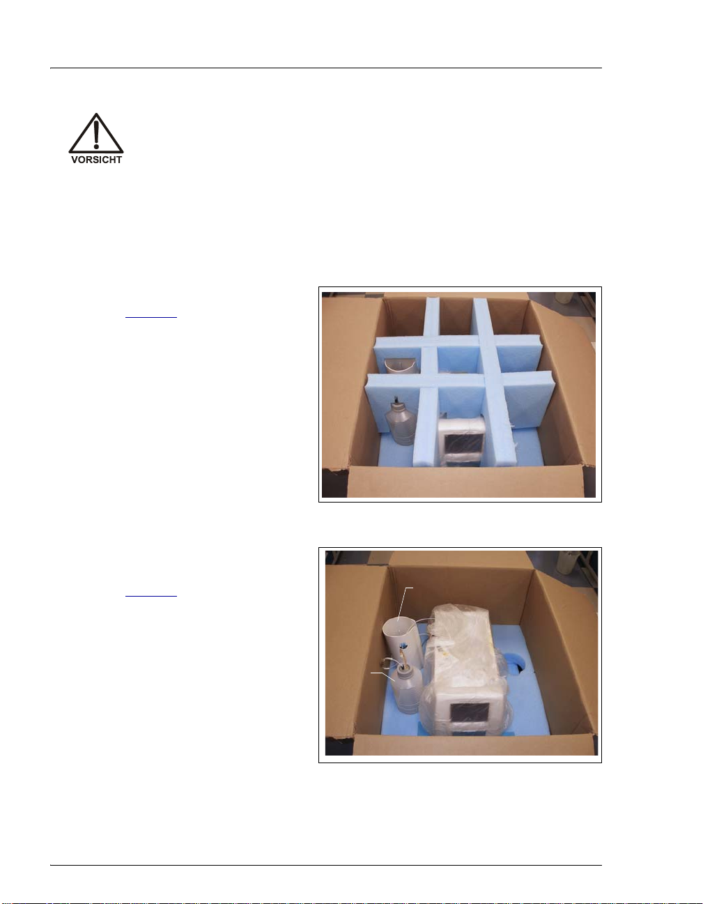
2. Unpacking the IC System
1. Open the shipping box (see
Figure 1
layer of foam.
) and remove the top
(Remove this foam)
Figure 1. Unpacking the ICS-2100
2. Open the plastic bag that
covers the IC system (see
Figure 2
2 Doc. 065294-01 3/09
).
Eluent
Bottle
Figure 2. IC System Enclosed in Bag
EGC Holder
(upside down)
Page 7
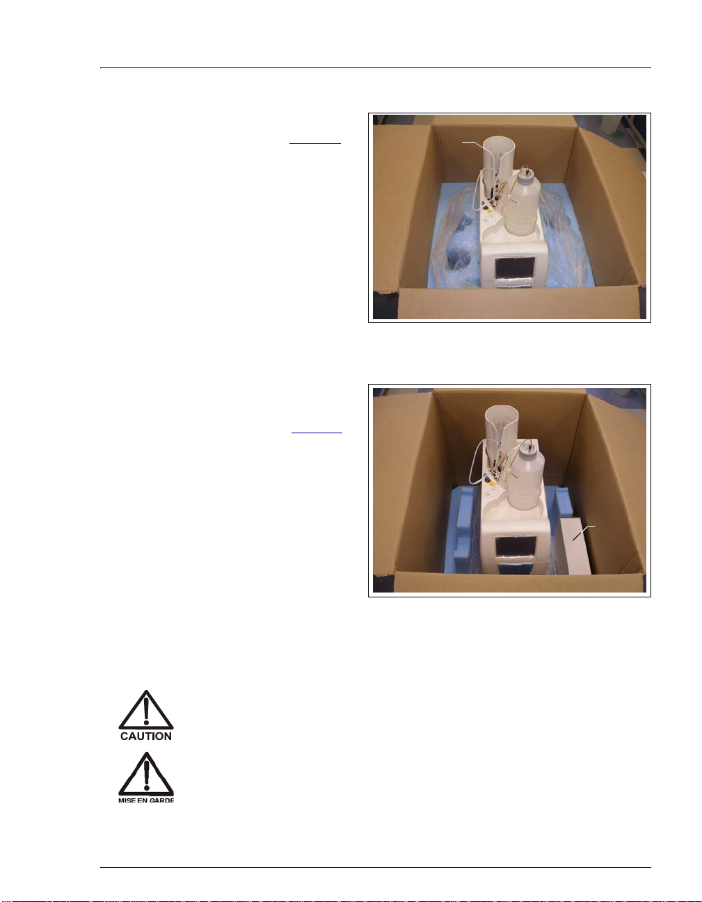
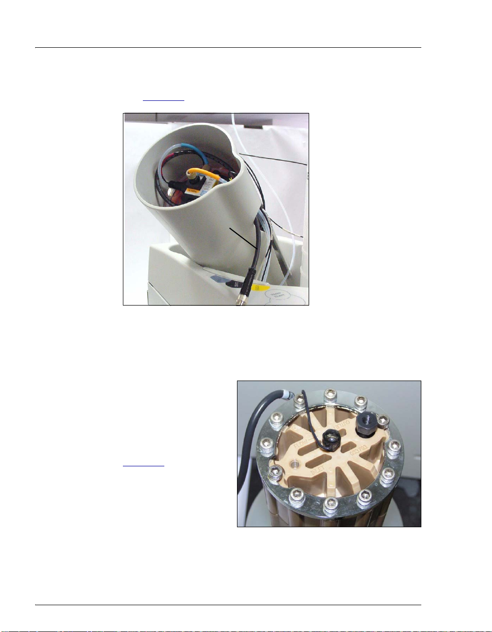
3. Set the eluent bottle on top of
the ICS-2100 (see Figure 3
).
4. TURN OVER THE EGC
HOLDER, and set it on top
of the ICS-2100.
5. Remove the next layer of
foam and remove the Ship Kit
(P/N 064375) (see Figure 4
).
6. The bottom layer of foam has
two cutouts on either side of
the module; use these as
handholds when lifting the IC
system.
Unpacking the IC System
EGC Holder
(right-side up)
Figure 3. ICS-2100 After Installing
Eluent Bottle and EGC Holder
Ship
Kit
Figure 4. IC System with Ship Kit
7. Lift the IC system off the bottom layer of foam and out of the box. Set it on a
workbench.
Two or more persons should lift the IC system, which weighs 30 kg
(66 lb). Lift the IC system only from each side of the cabinet bottom.
Lifting from the front door will damage the door hinges.
Au moins deux personnes peuvent soulever le chromatograph
ionique: il pèse 30 kg (66 lb). Ne soulevez le chromatograph ionique
que par chaque côté du fond de l'armoire. Son soulèvement par la
porte du panneau avant endommagera les charnières de la porte.
Doc. 065294-01 3/09 3
Page 8

ICS-2100 Installation Instructions
Das IC system wiegt über 30 kg. Daher sollte das Gerät nur von zwei
oder mehr Personen angehoben werden. Greife n Sie dazu an beiden
Seiten unter das Gerät. Heben Sie den Ionen chromatographen nicht
an der Vordertür an, da dadurch die Türangeln beschädigt werden
könnten.
8. Inspect the system for any shipping damage. Reme mber to save the shipping
container and all packing material. You will need them in future if the IC
system is shipped.
3. Connecting an Autosampler (Optional)
T o connect an AS-DV or AS Autosampler to the injection valve in the IC system,
follow the instructions in the appropriate section below.
Notes:
• If an optional auxiliary valve is installed in the ICS-2100, it can be used as the
injection valve, instead of the standard valve configured with each system.
After connecting the autosampler to the auxiliary valve (as described in the
appropriate section below), configure the valve as the injection valve in
Chromeleon. For instructions, refer to Installing the ICS-1100/1600/2100
Auxiliary Valve (Document No. 065288). The document is provided with the
valve.
• To connect an AS-HV Autosampler, refer to the instructions in the AS-HV
Autosampler Operator’s Manual (Document No. 065125). The manual is
provided on the Dionex Reference Library CD-ROM (P/N 053891 ).
3.1 Connecting an AS-DV Autosampler
1. Place the AS-DV to the left of the IC system on the workbench.
2. Open the IC system and the autosampler doors.
4 Doc. 065294-01 3/09
Page 9
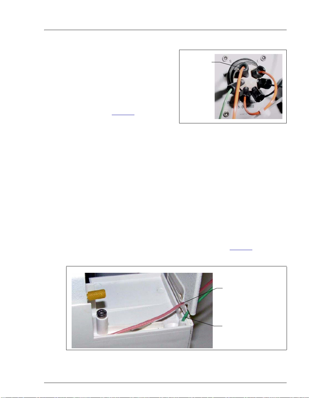
Connecting an Autosampler (Optional)
3. Route the sample outlet line
from the AS-DV through
the left side slot, at the front
Sample
Outlet Line
of the IC system.
4. Connect the outlet sample
line from the AS-DV to port
S(5) on the injection valve
(see Figure 5
).
Figure 5. IC System Injection Valve
3.2 Connecting an AS Autosampler
NOTE Dionex recommends using AS models that do not
have injection valves. If a valve is installed in the
autosampler, it is switched at the same time as the
valve in the IC system. This causes unnecessary
wear on the autosampler valve. If your AS has an
injection valve, contact Dionex for assistance.
1. Place the autosampler to the left of the IC system on the workbench.
2. Open the IC system and the autosampler doors.
AS-DV
3. Route the needle seal line that extends from the autosampler inject
port through the autosampler right side slot (see Figure 6
) and then
through the IC system left side slot to the injection valve.
Route the autosampler
needle seal line to the
injection valve inside
the IC system
Insert the waste line
from the IC system
injection valve here
Figure 6. AS Autosampler Drip Tray and Right Side Slot
Doc. 065294-01 3/09 5
Page 10
ICS-2100 Installation Instructions
The needle seal line from the AS autosampler inject port to the IC
system injection valve is specially constructed. It consists of two
tubes (one inside the other) that are seale d at the en d. This seal must
be maintained.
In addition, the line is calibrated for use with the IC system. To ensure
correct autosampler function, this line MUST NOT BE CUT! If
replacement is required, refer to the AS operator’s manual for the
required part number and replacement instructions.
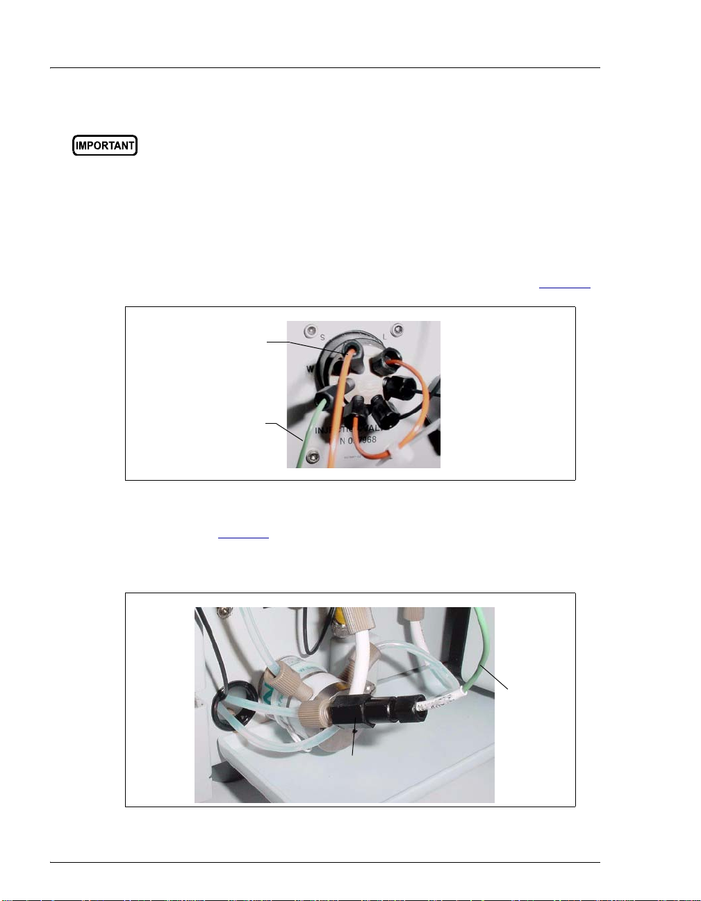
4. Connect the needle seal line to port S (5) on the injection valve (see Figure 7).
Autosampler
Needle Seal
Line
Waste
Line
Figure 7. Injection Valve
A coupler (see Figure 8
) connects the green waste line from port W (6) to a
3-mm (1/8-in) ID PTFE waste line. The waste line is routed through the
tubing chase to the IC system rear panel.
Green
Waste
Line
Coupler
Figure 8. Injection Valve Waste Line Coupler
6 Doc. 065294-01 3/09
Page 11
Connecting an Autosampler (Optional)
5. If the coupler is not visible, grasp the green waste line where it exits the
tubing chase and pull it toward the front of the system until the coupler is
outside the chase.
6. Disconnect the green waste line (labeled
TO AS50 TRAY) from the coupler and
route the line to the drip tray in the autosampler compartment.
You can either leave the disconnected PTFE waste line and coupler in the
tubing chase, or pull the line out from the front.
7. Bend the green waste line about 5 mm (0.2 in) from the end (to ensure it stays
in the AS drip tray). When bending the tubing, be sure not to restrict the inner
diameter.
8. Push the end of the green waste line into the small round opening on the right
side of the AS tray (see Figure 6
Make sure the injection valve waste line is not elevated above the
injection valve at any point between the valve and the autosampler
drip tray.
NOTE After the AS is configured for use with the ICS-2100
(see Section 12.2
supported. In addition, all injection valve
commands (whether issued from Chromeleon or the
AS front panel) can control the injection valve.
).
), all AS injection types are
Doc. 065294-01 3/09 7
Page 12

ICS-2100 Installation Instructions
4. Unpacking the PC
1. Remove the PC and all documentation from the PC box and place them on a
workbench.
2. Follow the instructions in the PC installation guide to connect the PC
components.
5. Installing Chromeleon
NOTE If you purchased Chromeleon and a PC from Dionex,
omit this section and go directly to “Starting the
Chromeleon Server” on page 12.
1. To verify that the PC meets current system specifications, go to
http://www.dionex.com
Specifications link.
2. Verify that the Chromeleon disk contains Chromeleon version 6.80 SR6a (or
later).
3. For a local PC: Log onto Windows
administrator.
, select Software under Products, and click the
®
XP or Windows® Vi sta® as an
For a network PC: Log on as a user with local PC administrator privileges.
4. Verify that at least 250 MB of free disk space is available on the drive on
which you plan to install Chromeleon.
More than 250 MB may be needed to store the large amounts of data that
Chromeleon can generate. Data can also be stored at a different location (for
example, on a network).
5. Insert the Chromeleon disk into the PC drive.
8 Doc. 065294-01 3/09
Page 13

Installing Chromeleon
The Chromeleon Setup screen appears (see Figure 9).
Figure 9. Chromeleon Setup screen
6. If you are installing Chromeleon on a PC that has an earlier release of
Chromeleon 6.80 already installed, click Update Chromeleon and follow the
on-screen instructions.
7. If you are installing Chromeleon on a PC that does not have an earlier release
of Chromeleon 6.80 installed, follow these steps to install Chromeleon:
a. On the Chromeleon Setup screen, click Exit.
b. Go to the following folder on the Chromeleon disk: CM680SRx (where x
is the service release number). For example, if you are installing
Chromeleon 6.80 SR6a, go to the CM680SR6a folder on the disk.
c. Double-click setup.exe and follow the on-screen instructions.
8. When asked whether to add the Server Monito r program to th e S tart up group,
select Yes if the PC will be physically connected to devices or No if the PC
will never be connected to devices.
9. After installing the software, restart the PC.
Doc. 065294-01 3/09 9
Page 14
ICS-2100 Installation Instructions
6. Installing the Chromeleon Software License Dongle
NOTE If your software license is provided through a
Chromeleon License Server, omit this section. Instead,
follow the instructions in the Chromeleon Help to install
the software license. Then, go on to “Connecting to the
Chromeleon PC” on page 13 .
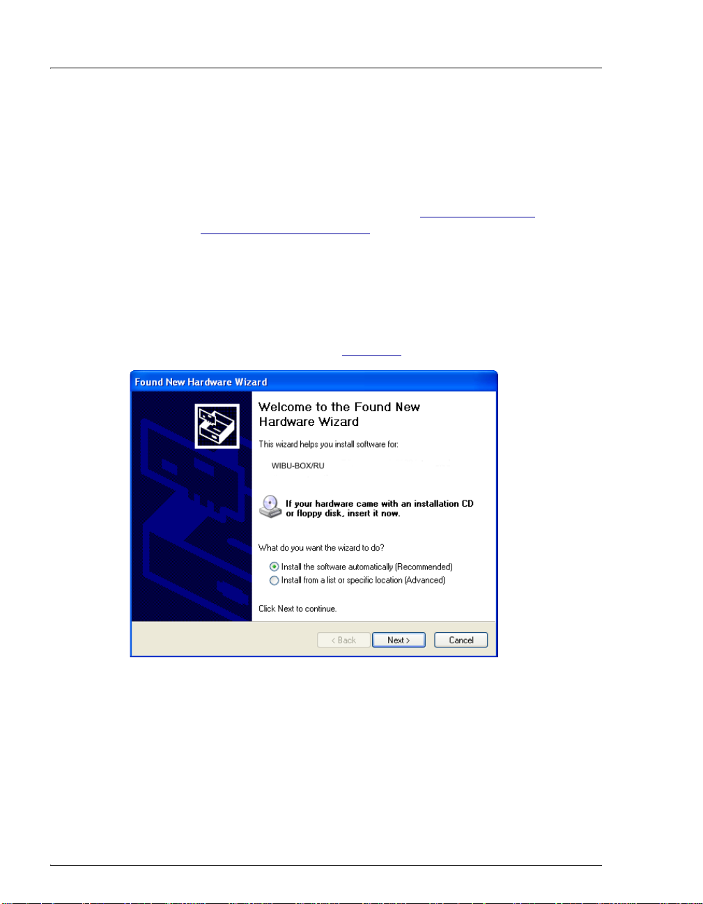
1. If your software license is issued with a USB dongle, plug the dongle into a
USB port on the PC. Always connect the USB dongle to the PC, not to a
Dionex module.
Microsoft
Found New Hardware Wizard (see Figure 10
®
Windows automatically detects the USB dongle and launches the
).
Figure 10. Windows Found New Hardware Wizard
2. Complete the wizard by selecting the following options:
• If asked whether Windows can connect to Windows Update to search for
software, select No, not this time.
• Accept the default option (Install the software automatically
(Recommended) option and click Next >. It is not necessary to insert a
10 Doc. 065294-01 3/09
Page 15
Installing the Software License
hardware installation disk. When the wizard has completed installing the
software, click Finish.
3. Store the Chromeleon disk in a safe place, away from heat and moisture.
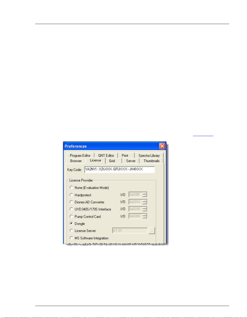
7. Installing the Software License
To activate the licensed features in Chromeleon, enter the license key code (an
alphanumeric series) provided on the Software License key code sheet. St o re the
key code sheet in a safe place.
1. Click Start on the Windows taskbar and select All Programs > Chromeleon
> Chromeleon to start the Chromeleon client.
2. Select Help > About Chromeleon.
3. Click the Preferences button and select the License tab (see Figure 11
Figure 11. Chromeleon License
4. Under Copy Protection Location, select Dongle and then enter the key code,
exactly as it appears on the key code sheet. Click OK.
).
Doc. 065294-01 3/09 11
Page 16
ICS-2100 Installation Instructions
5. The About Chromeleon Client screen should now display the serial number of
the dongle, and all purchased license features (devices controlled, number of
timebases, and software options) should be labeled On.
6. Click OK to close the screen.
8. Starting the Chromeleon Server
Check the Chromeleon Server icon on the Windows taskbar to determine if the
server is already running:
• If the icon is crossed out in red , the server is not running. Right-click the
icon and select Start Server.
• If the icon is gray , the server is already running.
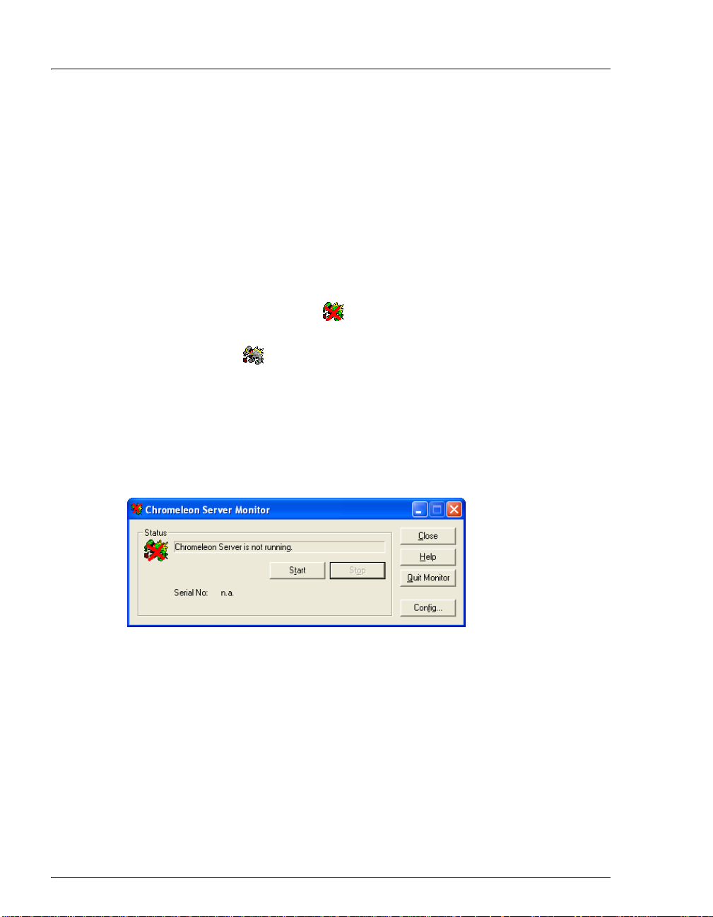
If the Server Monitor icon is not on the Windows taskbar, follow these steps to
start the Chromeleon server:
1. Click Start on the Windows taskbar and select Al l Programs > Chromeleon
> Server Monitor.
The Server Monitor window appears.
Figure 12. Server Not Running
2. Click Start to start the server.
3. Click Close to close the Server Monitor window.
The Server Monitor icon appears on the taskbar.
NOTE Clicking the Quit Monitor button quits (or exits) the
Server Monitor program, but does not stop the server.
To stop the server, click the Stop button.
12 Doc. 065294-01 3/09
Page 17
Connecting to the Chromeleon PC
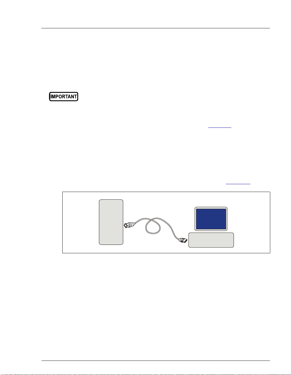
9. Connecting to the Chromeleon PC
The IC system rear panel provides a USB receptacle for connecting to a USB port
on the Chromeleon PC. The rear panel also provides two USB ports for
connecting other Dionex USB-compliant modules to the system.
Do not turn on the power to the ICS-2100 or other USB module(s) until
after you connect the USB cable.
Before connecting the USB cable, verify that Chromeleon is installed.
If not, Windows will be unable to identify the new USB device when
the power is turned on. To install Chromeleon, see Section 5
9.1 Connecting the IC System to the PC
1. Locate the USB cable (P/N 960779) in the IC system Ship Kit.
2. Plug the cable’s “A” connector into a USB port on the Chromeleon
PC and plug the cable’s “B” connector into the USB receptacle
(labeled
FROM PC) on the IC system rear panel (see Figure 13).
.
IC
System
B
USB Cable
A
PC
Figure 13. Example USB Connections: One IC System Connected to the PC
Doc. 065294-01 3/09 13
Page 18
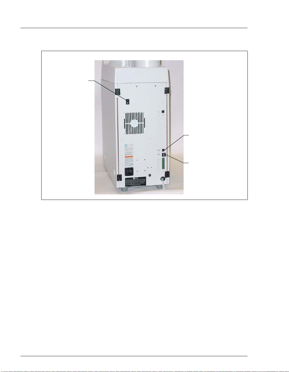
ICS-2100 Installation Instructions
Power
Switch
FROM PC
USB Receptacle
TO MODULE
USB Ports
Figure 14. IC System Rear Panel
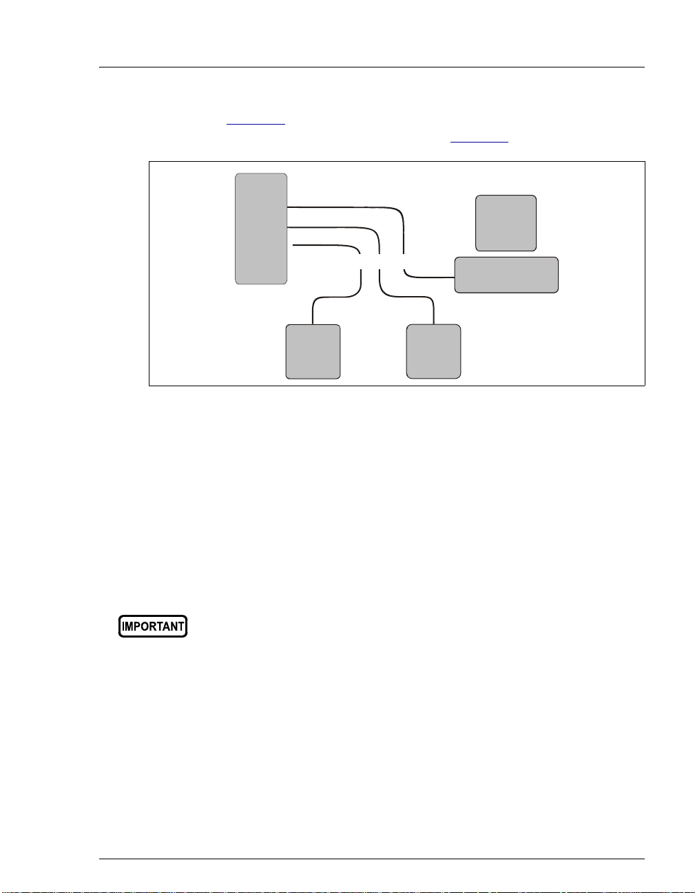
9.2 Connecting Additional USB Devices
Two USB ports on the IC system rear panel are provided for connecting
additional Dionex USB-compliant modules (for example, an autosampler)
to the system.
To connect an additional USB module, plug the “A” connector on a USB
cable into an “A” port (labeled
14 Doc. 065294-01 3/09
TO MODULE) on the ICS-2100 rear panel
Page 19
Connecting to the Chromeleon PC
A
(see Figure 14) and plug the cable’s “B” connector into the USB
receptacle on the other USB module (see Figure 15
IC
System
B
A
A
Dionex
USB
Module
USB Cables
Chromeleon
BB
Dionex
USB
Module
Figure 15. Example USB Connections: Two Dionex USB Modules
Connected to the IC System
A USB 2.0 external hub can be used to connect the modules to the PC.
Refer to the manual provided by the hub vendor for complete installation
instructions. One or more hubs is required in the following situations:
).
PC
• Use a hub if the number of USB devices in the system exceeds the
number of available USB ports.
• Use a hub if the IC system or other USB device is more than 5 meters
(16 ft) from the PC.
Doc. 065294-01 3/09 15
The USB standard limits the USB cable length to 5 meters (16 ft). Each
USB device can be separated from the PC by no more than five hubs.
Thus, each USB device can be located no more than 30 meters
(32 yds) from the PC.
Page 20
ICS-2100 Installation Instructions
10. Connecting the Power Cord
1. Verify that the main power switch on the rear panel of the ICS-2100 (see
Figure 14
accidentally when the module is unpacked.)
2. Connect the power cord (IEC 320 C13) (ordered separately) from the main
power receptacle on the rear panel to a grounded power source. The IC system
power supply is auto-sensing, so no adjustment is required to select the line
voltage.
) is turned off. (The main power switch may be turned on
SHOCK HAZARD—To avoid electrical shock, use a grounded
receptacle. Do not operate the IC system or connect it to AC power
mains without an earthed ground connection.
The power supply cord is used as the main disconnec t device. Make
sure the socket-outlet is located near the IC system and is easily
accessible.
Operation at AC input levels outside of the specified operating voltage
range may damage the IC system.
DANGER D'ÉLECTROCUTION—Pour éviter toute électrocution, il faut
utiliser une prise de courant avec prise de terre. Ne l'utilisez pas et ne
le branchez pas au secteur C.A. sans utiliser de branchement m is à la
terre.
Le cordon d'alimentation principal est utilisé comme dispositif
principal de débranchement. Veillez à ce que la prise de base soit
située/installée près du module et facilement accessible.
STROMSCHLAGGEFAHR—Zur Vermeidung von elektrischen
Schlägen ist eine geerdete Steckdose zu verwenden. Das Gerät d arf
nicht ohne Erdung betrieben bzw. an Wechselstrom angeschlossen
werden.
Das Netzkabel ist das wichtigste Mittel zur Stromunterbrechung.
Stellen Sie sicher, daß sich die Steckdose nahe am Gerät befindet und
leicht zugänglich ist.
16 Doc. 065294-01 3/09
Page 21

Installing the ICS-2100 Device Driver
11. Installing the ICS-2100 Device Driver
Before turning on the system power, verify that Chromeleon software
is installed. If Chromeleon is not installed first, Windows will be
unable to identify the new USB device. For Chromeleon installation
instructions, see Section 5
1. If you have not already done so, turn on the PC power.
2. For a local PC: Log onto Windows XP or Windows Vista as an
administrator.
For a network PC: Log on as a user with local PC administrator privileges.
.
3. If the Chromeleon Server is not running, start the server (see Section 8
4. Press the power switch on the ICS-2100 rear panel (see Figure 14
).
) to turn on
the power.
5. Turn on the power to the autosampler (if installed).
6. Windows automatically detects the new USB devices. A message flashes on
the screen to inform you that new hardware was found.
The Found New Hardware Wizard appears (see Figure 16
). This wizard
installs the new hardware into the Windows Device Manager.
Figure 16. Windows Found New Hardware Wizard: IC System Device
Doc. 065294-01 3/09 17
Page 22
ICS-2100 Installation Instructions
7. Complete the wizard for each new device by selecting the following options:
• If asked whether Windows can connect to Windows Update to search for
software, select No, not this time.
• Accept the default option (Install the software automatically) and click
Next >. It is not necessary to insert a hardware installation disk.
8. If any additional devices were found (for example, an autosampler) complete
the wizard for the device.
12. Setting Up Chromeleon
NOTE This section provides brief instructions for setting up
Chromeleon. For details about any of these steps, refer
to the Chromeleon Help.
12.1 Creating a Timebase
1. Click Start on the Windows taskbar and click All Programs >
Chromeleon > Server Configuration to start the Chromeleon Server
Configuration program.
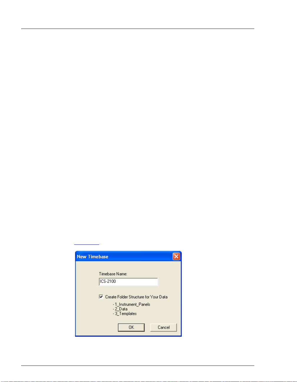
2. Select Edit > Add Timebase.
The New Timebase dialog box appears.
3. Type a name for the timebase (for example, ICS-2100) (see
Figure 17
Figure 17. Example New Timebase Dialog Box
18 Doc. 065294-01 3/09
).
Page 23
Setting Up Chromeleon
4. (Optional) Select the Create Folder Structure for Your Data
check box. This creates a standardized folder structure in the
Chromeleon Browser for the data related to your timebase.
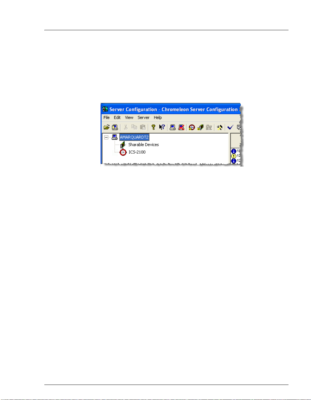
5. Click OK.
The new timebase appears under the server name.
Figure 18. Example Server Configuration with New Timebase
6. Right-click the new timebase and select Add Device.
The Add device to timebase dialog box appears.
7. Under Manufacturers, select Dionex IC: Integrated Systems.
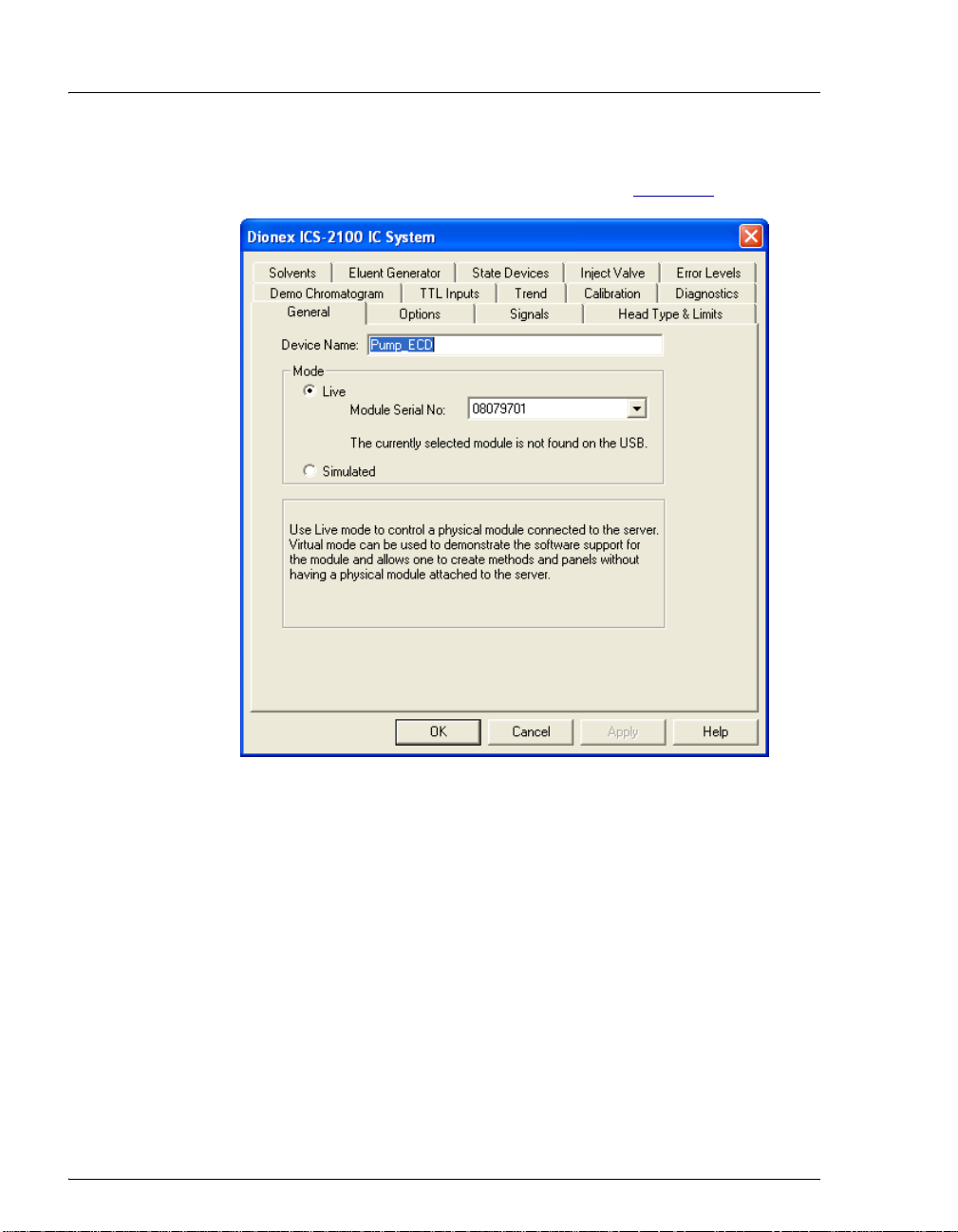
8. Under Devices, select ICS-2100 IC System and click OK.
The Properties dialog box for the IC system appears. The General tab
page shows the Device Name (Pump_ECD) and the Mode (Live).
Doc. 065294-01 3/09 19
Page 24
ICS-2100 Installation Instructions
9. Click the arrow next to Module Serial No. In the list, select the serial
number of the system you are configuring (see Figure 19
).
Figure 19. Example Properties Dialog Box: General Tab Page
20 Doc. 065294-01 3/09
Page 25
12.2 Configuring the Device Properties
NOTE For details about the settings on any of the
Properties tab pages, click the Help button.
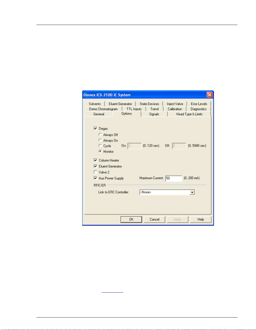
1. Click the Options tab and verify that the options installed in your IC
system are enabled.
Setting Up Chromeleon
Figure 20. Example Properties Dialog Box: Options Tab Page
To configure an auxiliary power su pply (optional):
To operate an electrolytic device such as a water polisher, you can
configure the EGC-2 power supply as an auxiliary power supply . The
power supply operates in constant current mode and can be
configured from 0 to 200 mA, with a maximum voltage of 35 V.
• On the Options tab page, select the AuxPower Supply check box
(see Figure 20
Doc. 065294-01 3/09 21
) and enter the Maximum Current allowed for the
Page 26
ICS-2100 Installation Instructions
electrolytic device (refer to the documentation provided with the
device).
• Connect the device to the EGC-2 connector on top of the ICS-
2100.
After the auxiliary power supply is configured, information about the
power supply (current, on, off, etc.) is displayed in Chromeleon and
on the front panel touch screens.
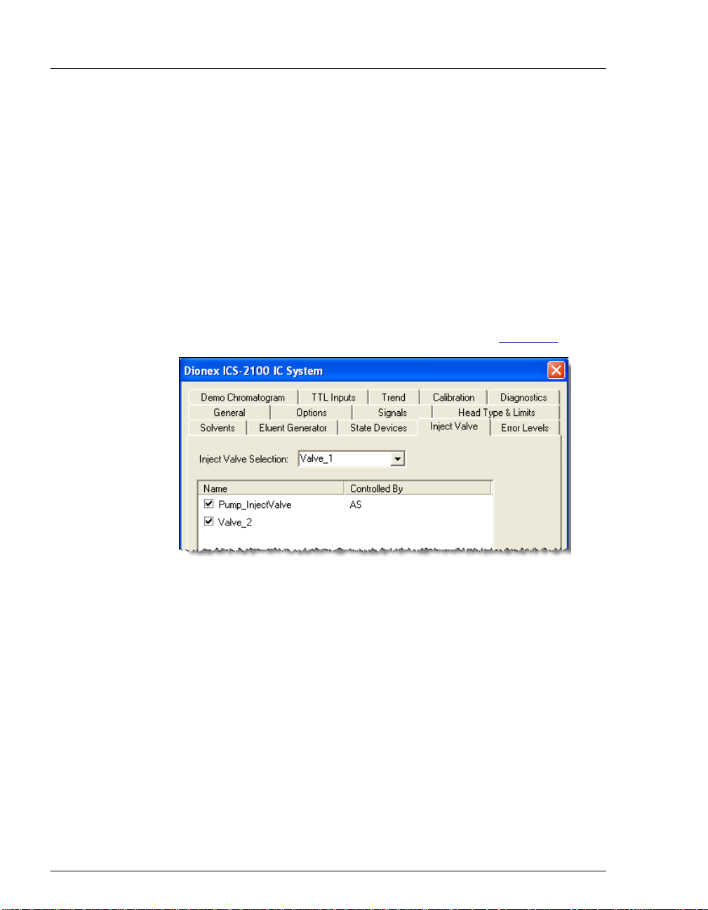
2. Click the Inject Valve tab and verify that the correct device is
assigned to control the injection valve in the ICS-2100.
• If the timebase will include an AS or AS-DV, the Controlled By
setting for Pump_InjectValve must be AS (see Figure 21
).
Figure 21. Inject Valve Properties: Inject Valve Controlled by the AS
22 Doc. 065294-01 3/09
Page 27
Setting Up Chromeleon
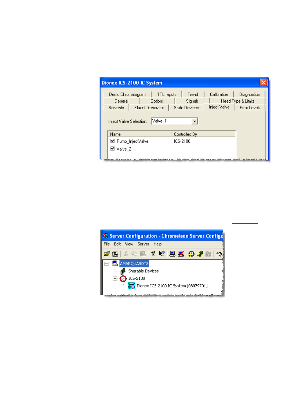
• If the timebase will include another model of autosampler (or no
autosampler), the Controlled By setting must be ICS-2100 (see
Figure 22
Figure 22. Inject Valve Properties: Inject Valve Controlled
To change a Controlled By setting, select the Pump_InjectValve
name, press F2, and select the device.
).
by the IC System
3. After selecting the device properties, click OK to close the dialog
box. The IC system is added to the timebase (see Figure 23
Figure 23. Example Server Configuration
with IC System Added to the Timebase
).
4. If you are configuring an autosampler, add the autosampler to the
timebase, as described for the IC system.
5. When the timebase is complete, select File > Save Installation.
Doc. 065294-01 3/09 23
Page 28
ICS-2100 Installation Instructions
6. You can ignore the “no inject device installed” warning, if it appears.
This simply means that the timebase does not include an autosampler.
This message appears if you are using manual injections. Close the
Server Configuration Check dialog box.
7. Exit the Server Configuration program.
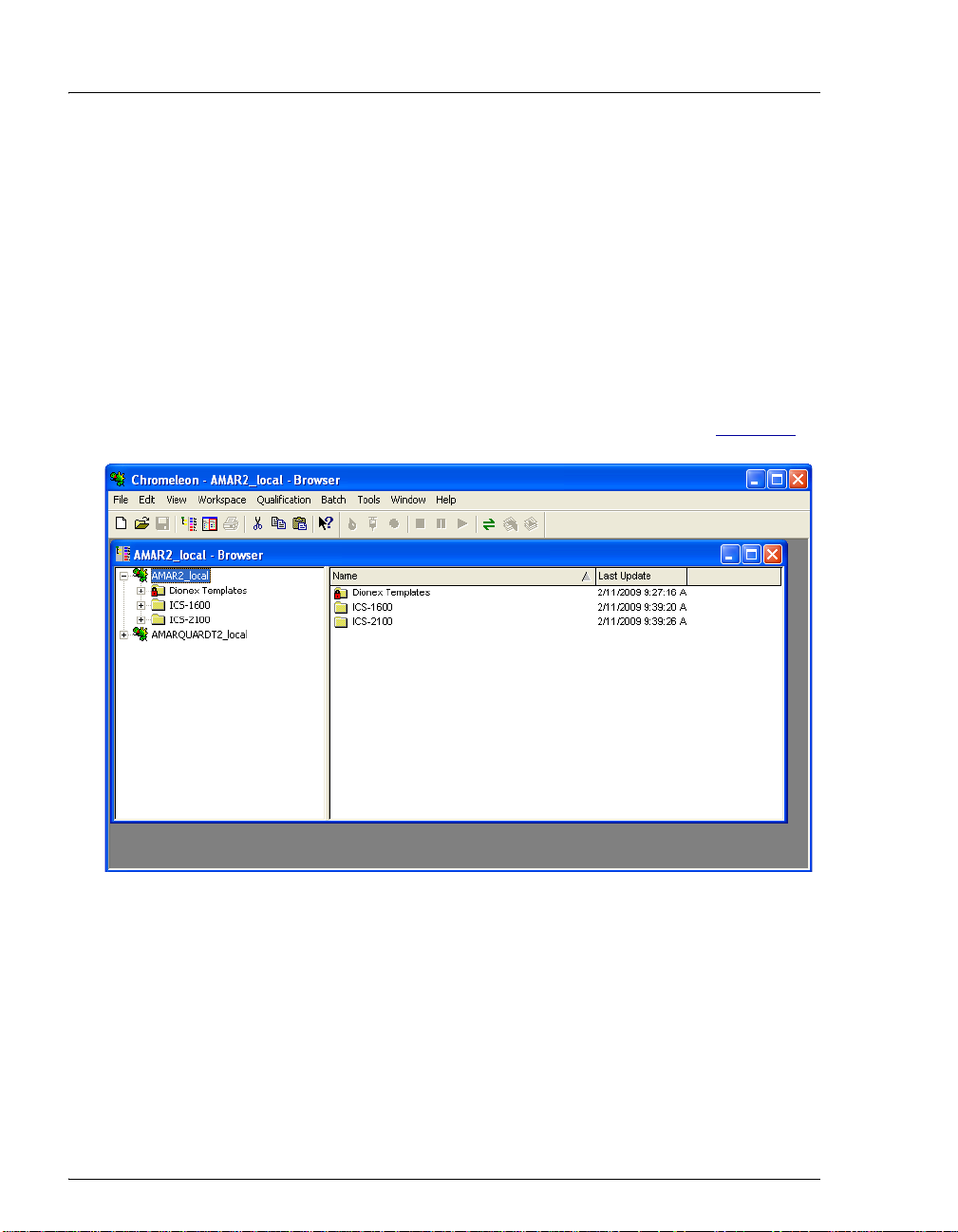
12.3 Connecting to the Panel Tabset
1. Click Start on the Windows taskbar and select All Programs >
Chromeleon > Chromeleon to start the Chromeleon client.
The Chromeleon main window and Browser appear (see Figure 24
Figure 24. Chromeleon Main Window and Browser
2. Select View > Default Panel Tabset to display the panel tabset.
).
24 Doc. 065294-01 3/09
Page 29
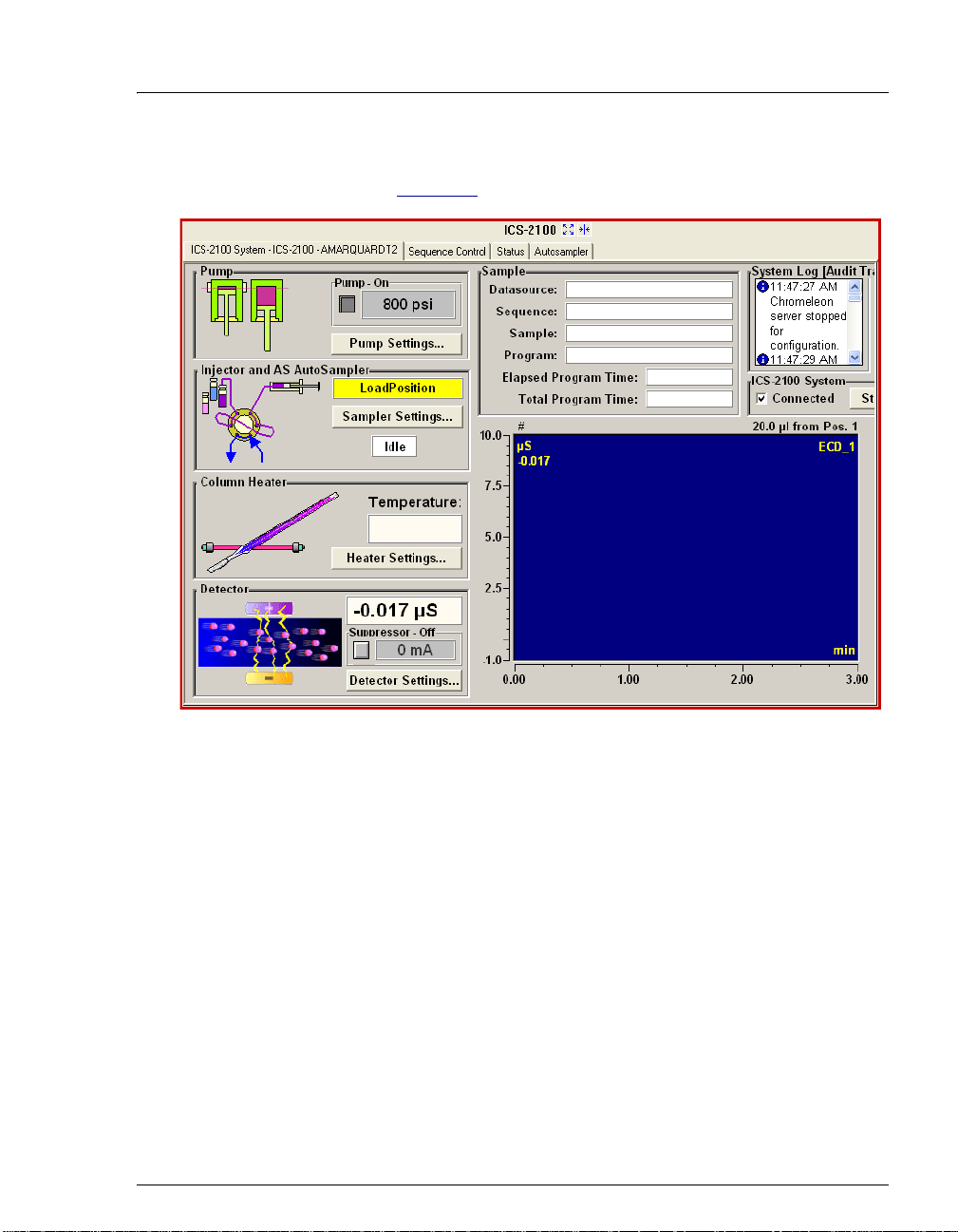
Setting Up Chromeleon
3. Click the ICS-2100 tab on the panel tabset to view the IC system
panel (see Figure 25
).
Figure 25. IC System Panel on the Chromeleon Panel Tabset
NOTE If an autosampler is installed, a separate Control
panel for the autosampler is included in the panel
tabset.
12.4 Verifying Chromeleon Communication
Verify that Chromeleon is communicating with the IC system by clicking
the
Inject and then the Load button on the panel. If communication is
occurring, you will hear the valve actuate as it changes position.
Doc. 065294-01 3/09 25
Page 30
ICS-2100 Installation Instructions
X
13. Installing and Plumbing the Columns and Suppressor
This section provides brief installation and plumbing instructions for the columns
and suppressor. For detailed start-up and installation instructions, refer to the
column and suppressor manuals. The manuals are provided on the Dionex
Reference Library CD-ROM (P/N 053891).
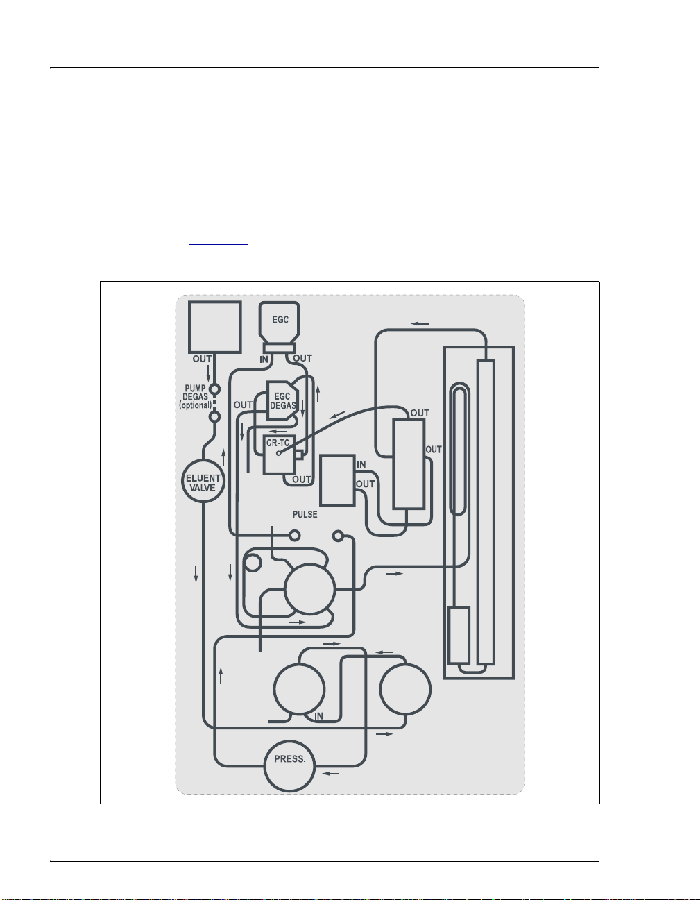
For reference, Figure 26
completed.
ELUENT
shows the system flow schematic after all plumbing is
OUT
IN
IN
IN
WASTE
SAMPLE
VALVE
DAMPER
S
W
L
COND
CELL
L
C
P
IN
HEAT EXCHANGER
COLUMN HEATER
SEPARATOR COLUMN
SUPPRESSOR
IN
GUARD
WASTE
OUT
WASTE
DUCER
PUMP
HEAD
OUT
OUT
PUMP
HEAD
IN
IN
Figure 26. IC System Plumbing Schematic
26 Doc. 065294-01 3/09
Page 31

Installing and Plumbing the Columns and Suppressor
13.1 Unpacking the Columns and Suppressor
1. Remove the guard column, separator column, and suppressor from
their boxes.
2. Remove the fitting plugs from the ends of each column and from all
ports on the suppressor.
3. Discard any tubing temporarily connecting the suppressor ports.
13.2 Setting Up the Column Heater
Note for 2-mm columns:
For best results with 2-mm columns, install a microbore heat exchanger
(P/N 060943) in the column heater. In addition, use red 0.125-mm
(0.005-in) ID PEEK™ tubing (P/N 044221), rather than the standard
black PEEK tubing, for tubing connections between the following
components:
• Injection valve and column heater heat exchanger
• Guard column and separator column
• Separator column and detector cell
Doc. 065294-01 3/09 27
Page 32
ICS-2100 Installation Instructions
To set up the column heater
1. Cut off the two shipping ties from the column heater and remove
them (see Figure 27
).
Thumbscrew (2)
Shipping Tie (2)
Figure 27. Column Heater with Shipping Ties
2. Loosen the two thumbscrews on the heater cover (they remain
attached to the cover).
3. Pull the heater cover straight out to remove it.
28 Doc. 065294-01 3/09
Page 33

Installing and Plumbing the Columns and Suppressor
4. Unscrew the six
thumbscrews on the top
metal plate (see
Figure 28
the plate.
) and remove
Thumbscrew (6)
Figure 28. Column Heater with Cover Removed
13.3 Plumbing the Columns
1. Remove the coupler connecting the lines labeled GUARD IN and
GUARD OUT.
2. Connect the
arrow on the guard column label; it should point down (flow away
from the injection valve).
3. Connect the
4. Push the guard column onto the back column clip.
5. Remove the coupler connecting the
6. Connect
the separator column outlet. Check the arrow on the column label. It
should point up (flow toward the cell).
7. Push the separator column onto the front column clips.
8. Replace the top metal plate on the column heater.
GUARD IN line to the guard column inlet. Check the
GUARD OUT line to the guard column outlet.
COL IN to the separator column inlet. Connect COL OUT to
COL IN and COL OUT lines.
Doc. 065294-01 3/09 29
Page 34
ICS-2100 Installation Instructions
13.4 Installing the Suppressor
1. Before installing the suppressor, hydrate it as instructed in the
suppressor manual. Suppressor manuals are provided on the Dionex
Reference Library CD-ROM (P/N 053891).
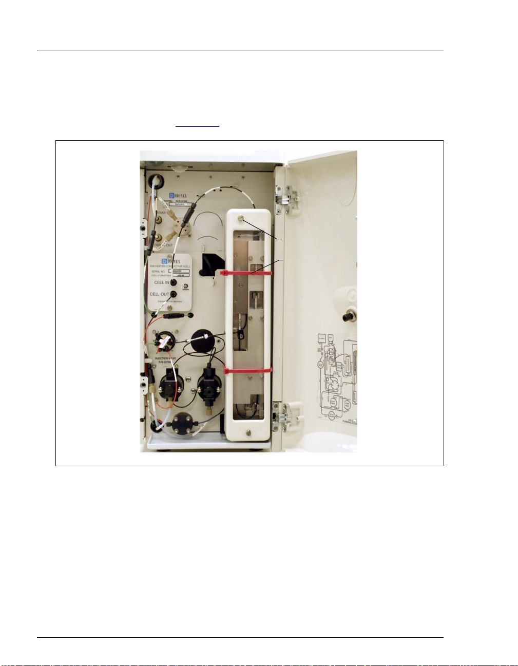
2. Locate the suppressor
mounting tabs on the
component panel (see
Figure 29
the opening between the
tabs and pull the yellow
connector and attached
cable slightly out of the
opening.
Connect this cable to the
cable from the
suppressor (align the
pins on the two
connectors and push
them together).
). Reach into
Suppressor
4
3
1
2
1
1
Mounting Tabs
Suppressor
2
Cable Connector
3
Guideline for
AES
4
Guideline for
SRS
1
®
®
Figure 29. Suppressor Mounting Tabs
and Guidelines
3. Orient the suppressor with the REGEN OUT fitting on top and the
cable to the right.
4. Feed the cable into the opening in the component panel.
5. Align the top of the suppressor with the guideline printed on the
component panel (see Figure 29
) and align the slots on the rear of the
suppressor with the tabs on the panel.
30 Doc. 065294-01 3/09
Page 35

Connecting the Waste Lines
6. Press the suppressor onto the tabs and
then slide it down to lock it in place. Pull
slightly on the center of the suppressor to
verify that it is securely fastened.
Figure 30
installed on the component panel.
shows an SRS® suppressor
7. Remove the coupler connecting the
ELUENT IN
and ELUENT OUT lines and
connect these lines to the corresponding
ports on the suppressor.
8. Remove the fitting plug from the REGEN IN line and connect it to the
REGEN IN port on the suppressor.
9. Do not connect the
REGEN OUT port until after completing the
eluent generator setup (Section 18
10. Replace the cover on the column heater, making sure the
line is aligned with the slot on the side of the heater cover.
14. Connecting the Waste Lines
Figure 30. Suppressor Installed
(SRS Shown)
).
GUARD IN
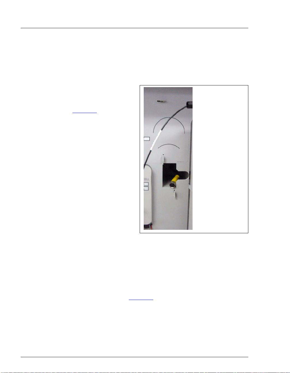
1. Untape the coiled waste lines from the rear panel. Place the ends of the PUMP
WASTE
2. Direct the
and TO WASTE OUT lines into a waste container.
WASTE, GAS SEPARATOR line from the top of the IC system to the
rear panel. Snap the line onto one of the tubing clips on the rear panel.
Connect the line to the waste, gas separator tube (see Section 14.1
NOTE To prevent waste from siphoning back into the system,
check the lines periodically to be sure they are not bent,
pinched, or elevated at any point.
Doc. 065294-01 3/09 31
).
Page 36
ICS-2100 Installation Instructions
14.1 Installing the Waste, Gas Separator Tube
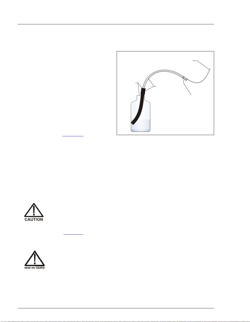
1. Locate the waste, gas
separator tube
assembly in the IC
(from the suppressor)
Waste, Gas
Separator Line
system Ship Kit.
Waste,
2. Connect the
GAS SEPARATOR
WASTE,
from the suppressor to
one of the 3-mm (1/8in) ID white PTFE
line
Open to
the air
Gas
Separator
Tube
Assembly
Connect this
line to a second
system,
if needed.
lines on the waste, gas
separator tube
assembly (see
Figure 31
).
Figure 31. Waste, Gas Separator Tube Installation
Waste
3. Place the waste, gas separator tube assesmbly into the waste
container. Make sure the tubing junction (where the white PTFE
tubing meets the black polyethylene tubing) is above the top of the
container and that the waste, gas separator tube and the waste
container are open to the atmosphere.
DO NOT CAP THE WASTE CONTAINER: In the ICS-2100, the Atlas
Electrolytic Suppressor and Self-Regenera ting Suppressor (SRS) use
an electrolytic process that results in the production of small amounts
of oxygen or hydrogen gas. To ensure that the gas is not trapped in a
closed container and allowed to concentrate, install a 1.3-cm (0.52-in)
ID black waste, gas separator tube (P/N 045460) in an uncapped waste
container. Connect the Waste, Gas Separator line to the waste tube
(see Figure 31
).
®
NE FERMEZ PAS LE CONTENEUR DE GAZ RÉSIDUEL: Le ICS-2100, le
Atlas Electrolytic Suppressor, et le Self-Regenerating Suppressor
(SRS) travaillent avec un proces d´électrolyse, qu i produit des petite s
quantités de gaz d´oxygène ou d´hydrogène. Afin de garantir que le
gaz ne soit pas enfermé dans un conteneur fermé et puisse s´y
concentrer, connectez un tube noir à gaz résiduel (diamètre intérieur =
1,3 cm; n° de commande 045460) à un conteneu r ouvert (non fermé).
Connectez le conteneur résiduel au tube résiduel/gaz séparateur
(désigné: « Waste, Gas Separator»).
32 Doc. 065294-01 3/09
Page 37

Setting Up the Eluent Reservoir
VERSCHLIESSEN SIE DEN ABFALLBEHÄLTER NICHT: Der ICS-2100 ,
Atlas Electrolytic Suppressor und Self-Regenerating Suppressor
(SRS) verwenden einen Elektrolyseprozess, wodurch kleine Mengen
an Sauerstoff und Wasserstoff entstehen. Führen Sie einen
schwarzen Gasabscheiderschlauch (ID = 1,3 cm; Bestell-Nr. 045460) in
einen offenen (unverschlossenen) Abfallbehälter, damit sich das Gas
nicht in einem geschlossenen Behälter sa mmelt und aufkonzentriert.
Verbinden Sie die mit Waste, Gas Separator bezeichnete Leitung mit
dem Abfallschlauch.
15. Setting Up the Eluent Reservoir
1. Rinse the eluent reservoir with ASTM filtered, Type I (18-megohm)
deionized water.
2. Fill the reservoir with ASTM filtered, Type I (18-megohm) deionized water.
3. Place the reservoir on top of the IC system.
4. Install the cap and handtighten.
5. Connect the liquid lines from the IC system to the corresponding lines exiting
the eluent bottle.
NOTE The IC system does not require pressurized reservoirs.
However, if eluent is manually degassed or is sensitive to
contamination, Dionex recommends pressurizing the
reservoir with helium or nitrogen. See Section 22
instructions.
Doc. 065294-01 3/09 33
for
Page 38

ICS-2100 Installation Instructions
16. Entering the Eluent Level
After filling the reservoir, enter the volume of liquid in the reservoir.
1. On the IC system
panel on the Chromeleon panel tabset, click the Pump
Settings button.
The Pump Settings window appears (see Figure 32
Enter the
volume of
liquid in the
reservoir
(in liters)
Figure 32. Pump Settings Window: Setting the Eluent Level
).
Note: The Eluent
Bottle field and
slider gauge are
updated as the
liquid is used up.
2. Use the slider to enter the volume (in liters), or enter the volume directly into
the Eluent Bottle box.
The IC system determines the eluent usage by monitoring the flow rate and the
length of time the pump is on, and updates the
Eluent Bottle volume as the eluent
is used up. A warning appears if the level falls below 200 mL. Warnings are
repeated at 100 mL and 0 mL.
In order for the level displayed in the Eluent Bottle box and gauge to
be accurate, you must enter the level when the reservoir is filled. The
IC system does not automatically detect when the reservoir is filled,
nor when it is empty.
If preferred
, you can enter the eluent bottle level on the touch screen HOME page,
instead of on the Chromeleon Control panel.
34 Doc. 065294-01 3/09
Page 39

17. Priming the Pump
1. Verify that the eluent reservoir is filled, the reservoir cap is installed and
handtightened, and the liquid line from the IC system to the reservoir cap is
connected (see Section 15
2. Verify that the waste lines are directed to a waste container.
3. The priming procedure consists of two parts:
• Priming the eluent lines with a syringe (see Section 17.1). Perform this
procedure at initial installation, after changing eluents, or when eluent
lines are empty.
• Priming the pump heads with the Prime button (see Section 17.2).
Perform this procedure after the eluent lines are primed.
17.1 Priming the Eluent Lines with a Syringe
NOTE Prime the eluent lines after initial installation, after
changing eluents, or when eluent lines are empty.
).
Priming the Pump
1. Verify that the pump is turned off.
2. Connect a 10 mL syringe (P/N 054578) to the priming valve port on
the primary pump head (see Figure 33
Secondary
Pump Head
Waste Valve
(close)
Port
10 mL Syringe
(P/N 054578)
Figure 33. Pump Head Valve Settings for Priming the Eluent Lines
).
Priming Valve
(open)
Primary
Pump Head
Doc. 065294-01 3/09 35
Page 40

ICS-2100 Installation Instructions
3. Open the priming valve by turning it one-quarter to one-half turn
counterclockwise.
4. On the IC system
panel on the Chromeleon panel tabset, click the
Pump Settings button.
The Pump Settings window appears (see Figure 34
Figure 34. Pump Settings Window
5. Under
Eluent Flow Valve, click Open.
).
6. Draw the syringe back to begin pulling eluent through the flow path.
It may take several syringe draws to remove all air or previous eluent
from the tubing. Draw out a minimum of 20 mL of eluent to ensure
that the vacuum degas assembly (if installed) is primed.
7. After priming the lines thoroughly, close the priming valve. Do not
overtighten the priming valve.
8. Under
36 Doc. 065294-01 3/09
Eluent Flow Valve, click Closed.
Page 41

Priming the Pump
d
(
)
17.2 Priming the Pump Heads with the Prime Button
NOTE Perform this procedure after priming the eluent
lines (see Section 1 7.1
1. Close the priming valve on the primary pump head (see Figure 35).
Secondary
Pump Head
Waste Valve
(open)
Priming Valve
).
Primary
Pump Hea
close
Figure 35. Pump Head Valve Settings for Priming the Pump Heads
2. Open the waste valve on the secondary pump head by turning the
knob one-quarter to one-half turn counterclockwise (see Figure 35
Opening the valve directs the eluent flow path to waste and eliminates
backpressure.
3. On the Pump Settings window, click the
the waste valve is open by clicking
Prime button. Confirm that
OK when the reminder message
appears. The pump will begin pumping at approximately 3 mL/min.
4. Continue priming the IC system until no air bubbles are exiting the
pump waste line.
5. On the Pump Settings window, click
Pump Off.
6. Close the waste valve. Do not overtighten. The pump is now ready
for operation.
NOTE If the two standard priming procedures described
above are unsuccessful, prime the pump with
isopropyl alcohol. See Chapter 5 in the IC system
operator’s manual for instructions.
).
Doc. 065294-01 3/09 37
Page 42

ICS-2100 Installation Instructions
18. Setting Up the Eluent Generator
Before Beginning
Remove the EluGen® cartridge (EGC) and the other items to be installed from
their shipping containers. Depending on the type of eluent to be generated, the
other items may include a Continuously Regenerated Trap Column (CR-TC), an
EPM Electrolytic pH Modifier, and/or an EGC CO
NOTE The EGC degas assembly is installed inside the EGC
holder at the factory.
The EluGen cartridge contains one of the following: a corrosive bas e
(KOH, LiOH, or NaOH), a corrosive acid (MSA), or a concentrated
solution. Wear protective eyewear and gloves when handling
K
2CO3
the cartridge.
La cartouche d'EluGen contient un de ce qui suit: une base corrosive
(KOH, LiOH, ou NaOH), un acide corrosif (MSA), ou une solution
concentrée de K
manipulant la cartouche.
Die EluGen-Kartusche enthält eine korrosive Base (KOH, Li OH oder
NaOH), oder eine korrosive Säure (MSA). Tragen Sie daher beim
Umgang mit der Kartusche eine Schutzbrille und Handschuhe.
. Porter des lunettes et des gants protectives en
2CO3
Mixer.
3
Refer to the EluGen cartridge, CR-TC, and EPM manuals for the optimal
operating conditions for your application. The manuals are provided on the
Dionex Reference Library CD-ROM (P/N 053891).
18.1 Eluent Generator Setup for KOH, LiOH, MSA, and NaOH Eluents
Follow the instructions in this section if you are installing a KOH, LiOH,
MSA, or NaOH EluGen cartridge and a CR-TC.
• If you are installing a K
Mixer (for generating carbonate/bicarbonate eluent), go to
Section 18.2
.
• If you are installing a K
generating carbonate eluent), go to Section 18.3
38 Doc. 065294-01 3/09
cartridge, an EPM, and an EGC CO
2CO3
cartridge and an EGC CO3 Mixer (for
2CO3
.
3
Page 43

Setting Up the Eluent Generator
Overview
The eluent generator setup procedure for KOH, LiOH, MSA, or NaOH
eluents consists of the following main steps:
• Installing the CR-TC.
• Installing the EluGen cartridge.
• Connecting the EluGen cartridge vent line.
• Recording the EluGen cartridge serial number in Chromeleon.
• Conditioning the EluGen cartridge.
• Hydrating the CR-TC.
• Completing the eluent generator setup.
Items Required to Complete the Setup Procedure
In addition to the EluGen cartridge and the CR-TC, you will need the
following items to complete the eluent generator setup.
Item P/N Use To
Yellow 0.5 mL/min, 7 MPa
(1000 psi) backpressure coil
(supplied in the ICS-2100
Ship Kit (P/N 064375))
EluGen Cartridge Vent Line
Tubing Kit
(supplied with the cartridge)
10-32 to 1/4-28 coupler
(supplied in the ICS-2100
Ship Kit)
Temporary waste container
(beaker, bottle, etc.)
(not supplied)
10-32 fittings
10-32 ferrules
1/8-in fittings
1/8-in ferrules
053765 Provide backpressure during
setup procedures.
063092 Vent the cartridge during
operation.
042806 Provide a temporary connection
during setup procedures.
n/a Collect waste during setup
procedures.
043275
043276
052267
048949
Complete the connections.
Complete the connections.
Doc. 065294-01 3/09 39
Page 44

ICS-2100 Installation Instructions
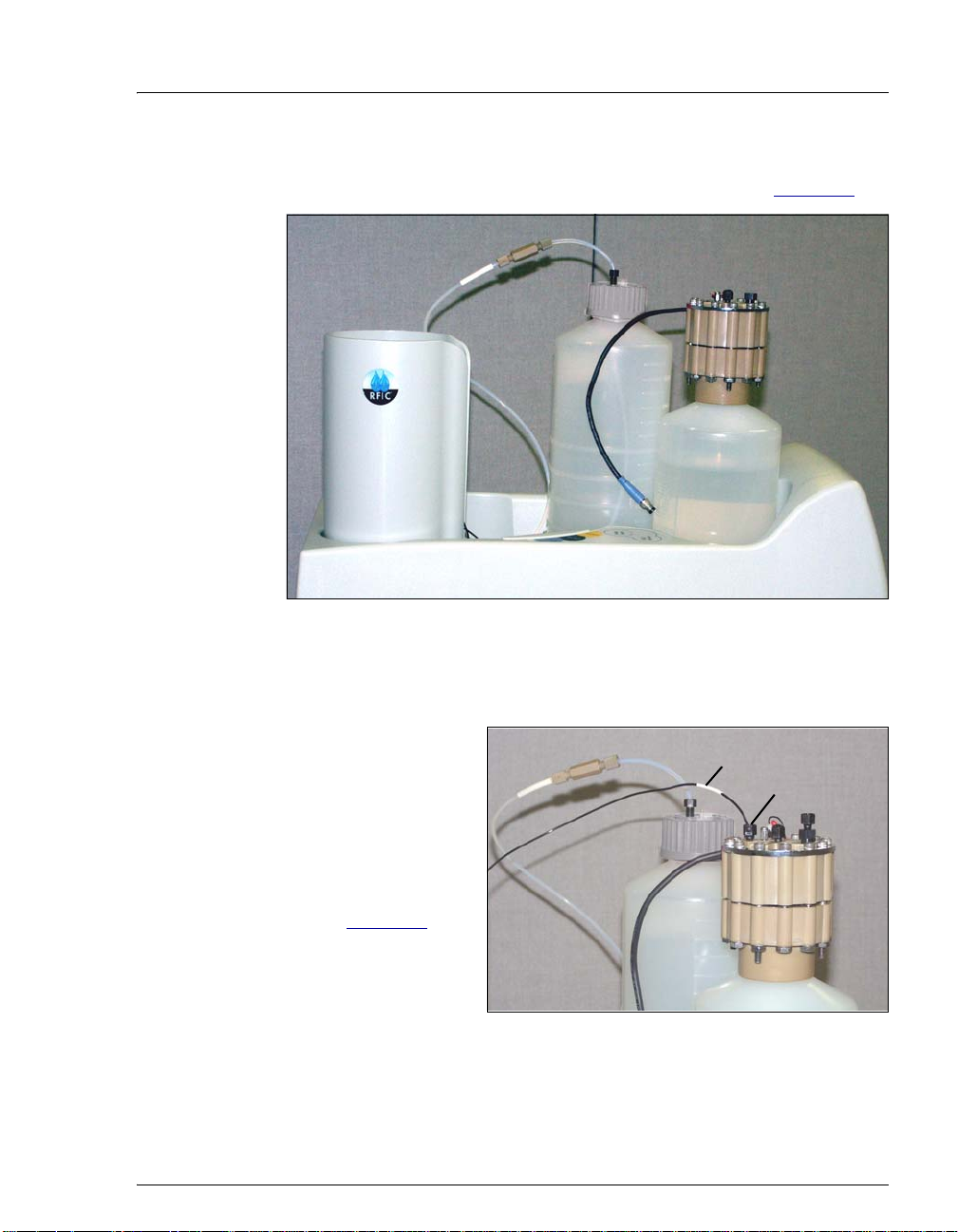
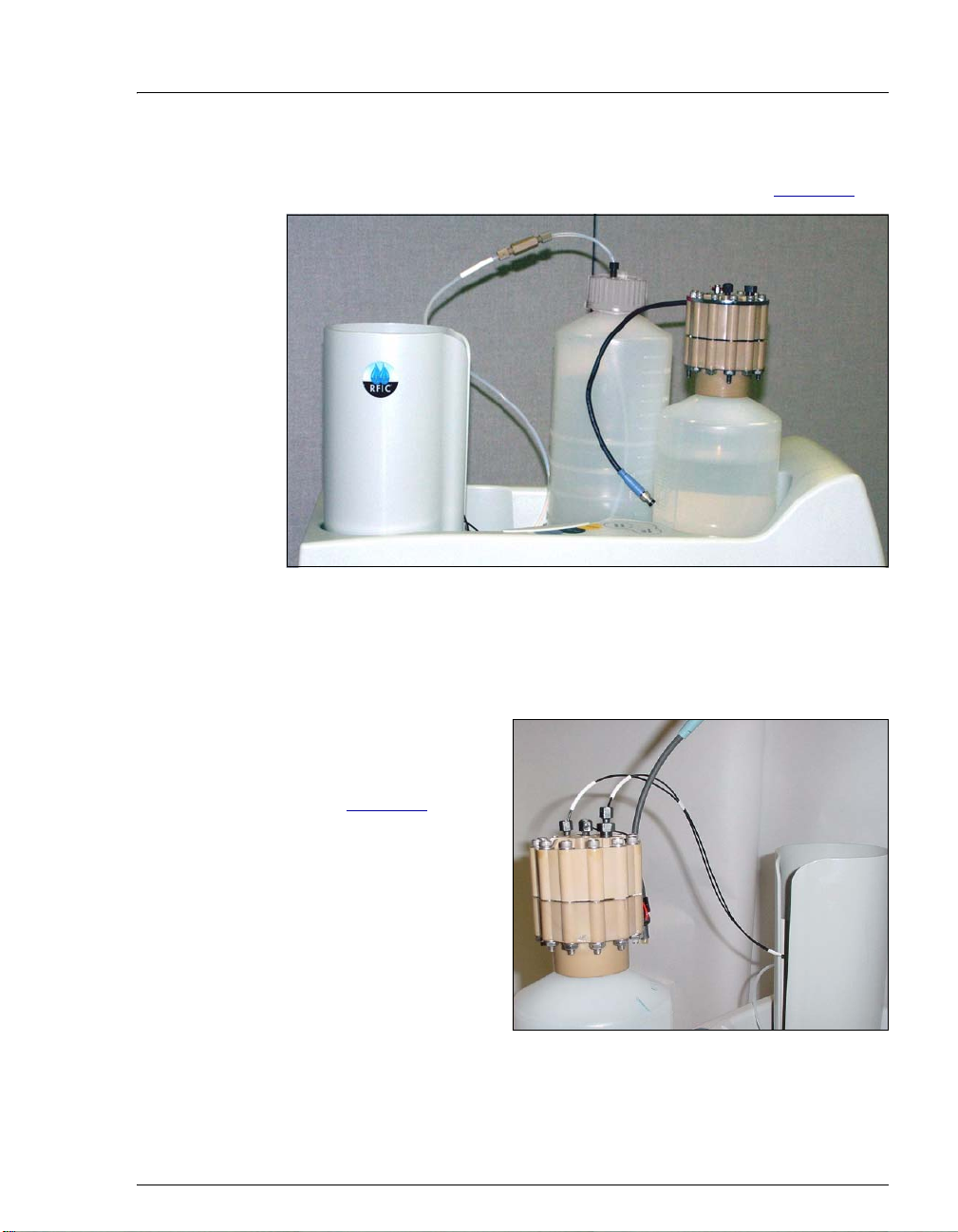
Figure 36 illustrates the ICS-2100 after the EluGen cartridge is installed.
IN EGC OUT
EluGen
Cartridge
(EGC)
EGC Holder
EGC and
CR-TC Cable
Connections
Figure 36. ICS-2100 with an EluGen Cartridge Installed (Top View)
40 Doc. 065294-01 3/09
Page 45

Setting Up the Eluent Generator
r
y
V
(2)
g
Figure 37 illustrates the liquid flow path through the eluent generator
components after all setup steps are complete and the eluent generator is
ready for operation.
EGC VENT
EGC II
KOH, LiOH,
MSA, or NaOH
Send to waste
Inlet Outlet
EGC
EGC
IN
OUT
TO CR-TC
ELUENT IN
(red)
TO PUMP/
DAMPER
Pre-plumbed
Pump Pulse
to
Damper
DEGAS
ELUENT OUT
TO DEGAS
ELUENT IN
TO DEGAS
ELUENT OUT
EGC
DEGAS
CR-TC
Eluent In
T
O
R
E
Regen In
Regen Out
G
(
o
r
a
Eluent
Out
TO CR-TC/EPM
ELUENT OUT
n
(yellow)
C
R
-
T
E
N
I
N
g
e
)
TO CR-TC
REGEN OUT
(blue)
C
Back-
pressure
Coil*
TO INJ
ALVE IN - P/
ELUENT OUT
Connect to
Inject Valve
Port P
*Add backpressure coils, if
needed, to create a system
backpressure of between 14 and
16 MPa (2000 and 2300 psi).
TO SRS/AES
REGEN OUT
Connect to
Suppressor
Re
en Out
Figure 37. Eluent Generator Flow Schematic with CR-TC:
Use for Generating KOH, LiOH, MSA, or NaOH Eluent
WASTE,
GAS
SEPARATOR
Connect to
Gas Separato
Assembl
Doc. 065294-01 3/09 41
Page 46

ICS-2100 Installation Instructions
Installing the CR-TC
1. Tilt the cartridge
holder to view the
bottom of the holder
and brace the holder
against the back corner
of the ICS-2100 (see
Figure 38
).
Figure 38. Cartridge Holder (Tilted to View the Bottom)
Metal ball stud
for mounting
the CR-TC
2. Before installing the
CR-TC, note the metal
ball stud inside the
bottom of the cartridge
holder (see Figure 38
E= Electrical connection (2)
(Do not remove)
P=Port (4)
(Remove plugs)
)
E
P
P
and the bracket on the
CR-TC mounting
plate (see Figure 39
These are used to
mount the CR-TC
).
P
P
E
inside the holder after
it is plumbed.
Figure 39. CR-TC
Bracket for mounting the
CR-TC on the holder
3. Remove the plugs from the four ports, labeled “P” in Figure 39. Do
not remove the two electrical connections, labeled “E” in the
figure.
42 Doc. 065294-01 3/09
Page 47

Setting Up the Eluent Generator
4. With the CR-TC oriented as shown in Figure 40, connect each line to
the corresponding port on the CR-TC.
NOTE To help retain the fittings and ferrules on the lines,
remove the coupler from each line just before
connecting the line to a port.
Regen Out
Eluent
Eluent In
Regen In
Out
Figure 40. Plumbed CR-TC
5. Check that none of the lines are caught under the CR-TC and then
push the CR-TC onto the metal stud inside the EGC holder (see
Figure 41
). Push down until the CR-TC snaps into place.
Figure 41. CR-TC Installed in Holder
Doc. 065294-01 3/09 43
Page 48
ICS-2100 Installation Instructions
6. Feed the CR-TC cable through the slot on the side of the EGC holder
(see Figure 42
Figure 42. Installing the CR-TC
).
CR-TC
Cable
7. Turn the EGC holder right-side up and set it back into position.
Installing the EluGen Cartridge
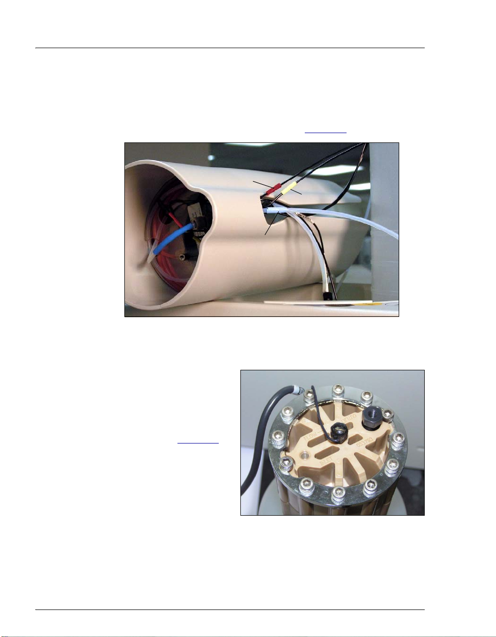
1. Orient the EluGen
cartridge with the fittings
facing up and remove the
plugs from the EluGen
cartridge
OUTLET ports (see
Figure 43
44 Doc. 065294-01 3/09
INLET and
).
OUTLET
INLET
Figure 43. EluGen Cartridge Inlet and Outlet Ports
Page 49
Setting Up the Eluent Generator
2. Set the EluGen cartridge in the service area on top of the ICS-2100
and orient it with the cable toward the EGC holder (see Figure 44
EGC Cable
Figure 44. EluGen Cartridge in Service Area
).
3. Pull the coiled black
EGC IN and EGC OUT lines out slightly from the
cartridge holder .
4. Disconnect the
IN line from the
union that connects
it to the
EGC OUT
EGC
EGC IN
INLET
Port
line.
5. Connect
the EGC
(see Figure 45
Doc. 065294-01 3/09 45
EGC IN to
INLET port
).
Figure 45. EGC Inlet Port Connections
Page 50
ICS-2100 Installation Instructions
6. Locate the yellow
0.5 mL/min, 7 MPa
(1000 psi)
backpressure coil
(P/N 053765) in the
ICS-2100 Ship Kit
(P/N 064375).
7. Connect one end of
this coil to the EGC
OUTLET
Figure 46
port (see
). Leave
the other end of the
coil unconnected.
Backpressure
Coil
OUTLET
Port
Figure 46. EGC Outlet Connection for
Conditioning the EGC
NOTE The backpressure coil connection is temporary; it is
required only during the EluGen cartridge
conditioning procedure described in “Conditioning
the EluGen Cartridge” on page 50.
8. Turn the EluGen cartridge over (with the fittings facing down). Shake
the EluGen cartridge vigorously , and tap it with the palm of your
hand 10 to 15 times. Check that all bubbles trapped in the eluent
generation chamber are dislodged.
The EluGen cartridge contains one of the following: a corrosive bas e
(KOH, LiOH, or NaOH), a corrosive acid (MSA), or a concentrated
solution. Wear protective eyewear and gloves when ha ndling
K
2CO3
the cartridge.
La cartouche d'EluGen contient un de ce qui suit: une base corrosive
(KOH, LiOH, ou NaOH), un acide corrosif (MSA), ou une solution
concentrée de K
manipulant la cartouche.
Die EluGen-Kassette enthält eine korrodierende Base (KOH, LiOH
oder NaOH), eine korrodierende Säure (MSA) oder eine konzentrierte
-Lösung. Tragen Sie daher beim Umgang mit Kassette eine
K
2CO3
Schutzbrille und Handschuhe.
. Porter des lunettes et des gants protectives en
2CO3
46 Doc. 065294-01 3/09
Page 51

Setting Up the Eluent Generator
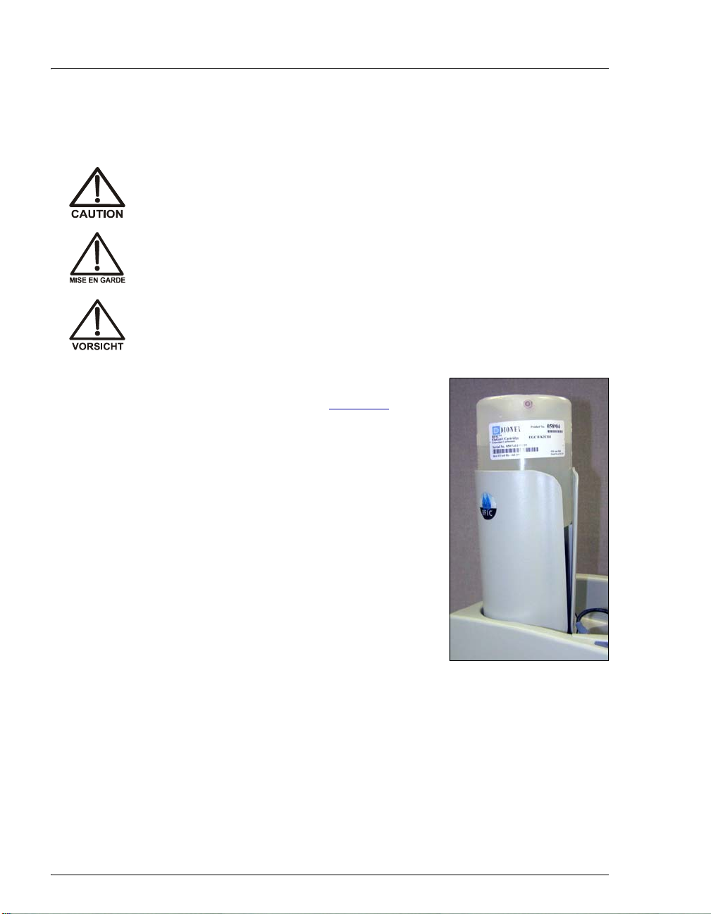
9. Slide the EluGen cartridge down
into the holder until it stops.
Make sure the cable and
backpressure coil remain out of
the holder (see Figure 47
NOTE To avoid crimping the
lines inside the holder, do
not twist the cartridge
when you slide it into the
holder. The lines are
designed to coil inside the
holder.
Figure 47. Installing the EluGen Cartridge in the Holder
).
10. Remove the plug from
the
EGC-1 connector on
top of the ICS-2100.
11. Orient the cartridge’s
blue 4-pin electrical
cable connector as
shown in Figure 48
Push it onto the
.
EGC-1
connector on the ICS-
2100. Twist the ring on
the cable connector
fingertight to secure it.
Figure 48. Connecting the EluGen Cartridge Cable
Doc. 065294-01 3/09 47
Page 52

ICS-2100 Installation Instructions
Connecting the Vent Line
1. Locate the vent line tubing kit (P/N 063092) supplied with the
EluGen cartridge. Slide the label onto one end of the tubing and then
push the barbed luer lock onto the tubing.
2. Unscrew and remove
the plug from the vent
opening on the side of
the EluGen cartridge
(see Figure 49
).
Vent Plug
(remove)
Figure 49. EluGen Cartridge Vent Plug
3. Screw the luer adapter
onto the vent opening.
Luer Adapter
Luer Lock
Remove the cap on
the luer adapter by
twisting. Save the
cap.
EGC Vent Line
4. Twist the luer lock
and EluGen cartridge
vent line into the luer
adapter (see
Figure 50
NOTE To prevent leaks from the EluGen cartridge, always
).
Figure 50. Installing the EluGen Cartridge Vent Line
replace the luer adapter cap before moving the
EluGen cartridge.
5. Direct the EluGen cartridge vent line to the rear of the ICS-2100 and
snap it onto one of the tubing clips on the rear panel.
6. Direct the vent line to the waste container and insert it down into the
waste, gas separator tube about 10 to 15 cm (4 to 6 in).
48 Doc. 065294-01 3/09
Page 53

Setting Up the Eluent Generator
Recording the EluGen Cartridge Serial Number in Chromeleon
The serial number is printed on the EluGen cartridge label.
1. Open the Chromeleon Server Configuration program (select Start >
Programs > Chromeleon > Server Configuration).
2. Double-click the ICS-2100 system icon. The properties dialog box for
the ICS-2100 appears.
3. Click the Eluent Generator tab (see Figure 51
).
4. Select the EGC-1 check box and enter the EluGen cartridge serial
number.
5. Click OK.
Figure 51. Eluent Generator Configuration Properties: OH Example
Doc. 065294-01 3/09 49
Page 54
ICS-2100 Installation Instructions
Conditioning the EluGen Cartridge
After completing the installation steps described in the previous sections,
condition the EluGen cartridge for 30 minutes.
1. Set a temporary waste container, such as a beaker, on top of the
ICS-2100 and direct the yellow backpressure coil from the EluGen
cartridge
OUTLET port to the container.
2. On the ICS-2100 touch screen
HOME page, set the pump flow rate to
1.00 mL/min.
3. Touch the
GENERATOR
EGC button on the HOME page to open the ELUENT
page. Set the EGC concentration to 50 mM.
4. Verify that the suppressor and CR-TC are off.
To avoid damaging the suppressor and CR-TC, always turn off the
suppressor and CR-TC before condition ing the EluGen c artridge. Th e
pump flow is on during conditioning, ho wever, no flow reaches the
suppressor or CR-TC.
5. Verify that the
selected on the ICS-2100 touch screen
ELUENT GENERATOR page. Disabling these options lets you turn on
Automatically turn on with pump options are not
SUPPRESSOR page and
the pump, without automatically turning on the suppressor and CRTC.
6. Verify that the eluent reservoir is filled with ASTM filtered, Type 1
(18 megohm-cm) deionized water (see Section 15
).
7. Turn on the pump.
8. Turn on the EluGen cartridge.
9. Run at the selected settings (1.00 mL/min at 50 mM) for 30 minutes.
10. Turn off the EluGen cartridge.
11. Turn off the pump.
12. Disconnect the EluGen cartridge cable.
13. Remove the backpressure tubing from the waste container and
remove the waste container.
14. Lift the EluGen cartridge out of the holder, turn it over, and set it in
the service area.
50 Doc. 065294-01 3/09
Page 55

Setting Up the Eluent Generator
15. Disconnect the
backpressure coil
from the EluGen
cartridge
port
16. Connect the EGC
OUT
OUTLET port (see
Figure 52
17. Turn over the EluGen cartridge. Check for bubbles; if necessary,
shake and tap the EluGen cartridge to remove bubbles.
OUTLET
.
line to the
).
Figure 52. EGC Inlet and Outlet Connections
18. Reinstall the EluGen cartridge in the holder.
19. Do not reconnect the EluGen cartridge cable until after hydrating the
CR-TC.
Hydrating the CR-TC
Always hydrate the CR-TC before initial operation. This requires running
ASTM filtered, T ype 1 (18 megohm-cm) deionized water through the CRTC for 10 minutes, while bypassing the columns and suppressor.
Doc. 065294-01 3/09 51
Page 56

ICS-2100 Installation Instructions
Figure 53 illustrates the liquid flow path through the CR-TC during the
hydration procedure.
Deionized water
in from pump
TO EGC
OUT
TO CR-TC
ELUENT IN
(red)
DEGAS
ELUENT OUT
TO DEGAS
ELUENT IN
TO DEGAS
ELUENT OUT
EGC
DEGAS
CR-TC
Eluent In
T
R
E
Regen In
Regen Out
(
o
r
Eluent
Out
TO CR-TC/EPM
ELUENT OUT
a
(yellow)
O
C
G
E
N
n
g
e
TO CR-TC
REGEN OUT
R
-
T
C
I
N
)
(blue)
10-32 to
TO INJ
VALVE IN - P/
ELUENT OUT
1/4-28 Coupler
TO SRS/AES
REGEN OUT
Figure 53. CR-TC Plumbing for Hydration
1. Disconnect the
TO INJ VALVE IN - P/ELUENT OUT line from port P (2)
on the injection valve.
2. Disconnect the
TO SRS/AES REGEN OUT line from the suppressor.
3. Use a 10-32 to 1/4-28 coupler (P/N 042806) to connect the
VALVE IN - P/ELUENT OUT
line to the SRS/AES REGEN OUT line.
4. Verify that the suppressor is off.
WASTE,
GAS
SEPARATOR
TO INJ
To avoid damaging the suppressor, always turn off the suppressor
before hydrating the CR-TC. The pump flow is on during conditio ni ng ,
however, no flow reaches the suppressor.
5. Verify that the
selected on the ICS-2100 touch screen
Automatically turn on with pump option is not
SUPPRESSOR page. Disabling
52 Doc. 065294-01 3/09
Page 57

Setting Up the Eluent Generator
this option lets you turn on the pump, without automatically turning
on the suppressor.
6. Turn on the pump and set the flow to the rate recommended for your
application.
7. Pump deionized water through the CR-TC for at least 10 minutes.
8. Turn off the pump and remove the coupler.
Completing the Eluent Generator Setup
1. Reconnect the TO SRS/AES REGEN OUT line to the REGEN OUT port
on the suppressor.
2. Reconnect the
TO INJ VALVE IN - P/ELUENT OUT line to port P (2) on
the injection valve.
3. Reconnect the EluGen cartridge cable.
4. Remove the plug from the
CR-TC connector on top of the ICS-2100
5. Orient the CR-TC’s
black 3-pin electrical
cable connector as
shown in Figure 48
Push it onto the
connector on the
TC
.
CR-
ICS-2100. Twist the
ring on the cable
connector and
fingertighten to
secure it.
Figure 54. Connecting the CR-TC Cable
NOTE Backpressure tubing may be required between the
injection valve and the EGC degas eluent outlet.
The EluGen cartridge requires 14 to 16 MPa (2000
to 2300 psi) of system backpressure for removal of
electrolysis gas from the eluent produced by the
cartridge. See Section 19.1
for details.
6. Go on to Section 19, “Equilibrating the System.”
Doc. 065294-01 3/09 53
Page 58

ICS-2100 Installation Instructions
18.2 Eluent Generator Setup for Carbonate/Bicarbonate Eluent
Follow the instructions in this section if you are installing a K2CO3
cartridge, an EPM, and an EGC CO
carbonate/bicarbonate eluent).
Mixer (for generating
3
• If you are installing a K
generating carbonate eluent), go to Section 18.3
cartridge and an EGC CO3 Mixer (for
2CO3
.
• If you are installing a KOH, LiOH, MSA, or NaOH EluGen cartridge
and a CR-TC, go to Section 18.1
Overview
The eluent generator setup procedure for carbonate/bicarbonate eluent
consists of the following main steps:
.
• Installing the EluGen cartridge.
• Connecting the EluGen cartridge vent line.
• Installing the EPM.
• Plumbing the EPM for conditioning.
• Recording the EluGen cartridge and the EPM serial numbers in
Chromeleon.
• Conditioning the EluGen cartridge and the EPM.
• Installing the EGC CO
• Temporarily filling the EGC CO
• Filling the EGC CO
Mixer.
3
Mixer with deionized water.
3
Mixer with eluent of the required concentration.
3
• Completing the eluent generator setup.
54 Doc. 065294-01 3/09
Page 59

Setting Up the Eluent Generator
Items Required to Complete the Setup Procedure
The following items are required to setup the EluGen cartridge, EPM, and
EGC CO
Ship Kit (P/N 064375).
Item P/N Used To
EPM mounting bracket 063624 Mount the EPM on the EGC holder.
Mixer. Except as noted, all items are supplied in the ICS-2100
3
35 cm (14 in) of black 0.25-mm
(0.010-in) ID PEEK tubing
30 cm (12 in) of black 0.25-mm
(0.010-in) ID PEEK tubing
28 cm (11 in) of clear 1.58-mm
(0.062-in) ID PTFE tubing
EluGen Cartridge Vent Line
Tubing Kit (supplied with the
cartridge)
Yellow 0.5 mL/min, 7 MPa
(1000 psi) backpressure coil
EGC CO
Mixer mounting clips 063642 Install the mixer.
3
Phillips head screwdriver
(not supplied)
35 cm (14 in) of black 0.25-mm
(0.010-in) ID PEEK tubing
60 cm (24 in) of black 0.25-mm
(0.010-in) ID PEEK tubing
064340 Lengthen the line between the EGC degas
eluent inlet and the EPM
ELUENT OUT port.
064334 Lengthen the line between the EluGen
cartridge outlet and the EPM
ELUENT IN
port.
064337 Lengthen the line between the EGC degas
regenerant inlet and the EPM
REGEN OUT
port.
063092 Vent the cartridge during operation.
053765 Provide backpressure during setup
procedures.
n/a Install the EGC CO
Mixer mounting clips.
3
064346 Connect the EGC degas eluent outlet and the
EGC CO
064343 Connect the EGC CO
(
2) on the injection valve.
Mixer inlet.
3
Mixer outlet to port P
3
Temporary waste container
n/a Collect waste during setup procedures.
(beaker, bottle, etc.) (not supplied)
10-32 to 10-32 coupler
10-32 to 1/4-28 coupler
10-32 fittings
10-32 ferrules
1/8-in fittings
1/8-in ferrules
Doc. 065294-01 3/09 55
042627
042806
043275
043276
052267
048949
Complete the connections.
Complete the connections.
Complete the connections.
Page 60

ICS-2100 Installation Instructions
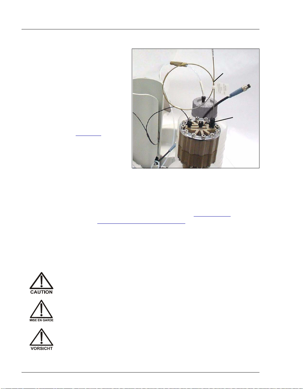
Figure 55 illustrates the EluGen cartridge and EPM after installation.
EluGen
Cartridge
(EGC
EGC Holder
EPM
Figure 55. ICS-2100 with an EluGen Cartridge and EPM Installed
56 Doc. 065294-01 3/09
Page 61

Setting Up the Eluent Generator
V
r
g
Figure 56 illustrates the liquid flow path through the eluent generator
components after all setup steps are complete and the eluent generator is
ready for operation.
EGC VENT
EGC II
KCO
23
Send to waste
TO PUMP/
DAMPER
TO INJ
ALVE IN - P/
ELUENT OUT
Pre-plumbed
Pump Pulse
to
Damper
*Add backpressure coils, as
needed, to create a system
backpressure of between 14 and
16 MPa (2000 and 2300 psi).
TO DEGAS
ELUENT IN
TO DEGAS
ELUENT OUT
EGC CO
Mixer
TO EGC CO3
MIXER IN
Inlet
EGC
(yellow
label)
TO EGC CO3
MIXER OUT
3
EGC
OUT
IN
EGC
DEGAS
TO INJ VALVE
PORT P
Connect
Inject Valve
to
Port P (2)
Outlet
O
T
R
(blue
label)
Back-
pressure
Coil*
TO CR-TC/EPM
ELUENT OUT
(yellow label)
P
E
/
C
T
-
O
R
C
N
E
G
a
l
E
e
u
l
b
(
label)
M
U
e
b
(red
T
)
l
ELUENT IN
TO
EPM
TO CR-TC/EPM
REGEN IN
(orange label)
TO SRS/AES
REGEN OUT
Connect to
Suppressor
Re
en Out
M
P
E
/
N
I
C
)
l
T
T
e
-
N
b
R
E
a
l
C
U
d
L
e
E
r
(
WASTE,
GAS
SEPARATOR
Connect to
Gas Separato
Assembly
Figure 56. Eluent Generator Flow Schematic with an EPM and EGC CO3 Mixer:
Use for Generating Carbonate/Bicarbonate Eluent
Doc. 065294-01 3/09 57
Page 62

ICS-2100 Installation Instructions
Installing the EluGen Cartridge
1. Tilt the cartridge
holder to view the
bottom and brace the
holder against the back
corner of the ICS-2100
(see Figure 57
).
Figure 57. Cartridge Holder (Tilted to View the Bottom)
58 Doc. 065294-01 3/09
Page 63

Setting Up the Eluent Generator
2. Use the precut tubing assemblies included in the ICS-2100 Ship Kit
to extend the length of three lines as described below:
a. Disconnect the
coupler that connects it to the
label). Connect a 32 to 10-32 coupler to the end of the
ELUENT IN line and connect the 30 cm (12 in) length of black
TO CR-TC ELUENT IN line (red label) from the
TO CR-TC ELUENT OUT line (yellow
TO CR-TC
PEEK tubing (red labels) (P/N 064334) to the coupler (see
Figure 58
).
b. Connect the 35 cm (14 in) length of black PEEK tubing (yellow
labels) (P/N 064340) to the coupler on the
TO CR-TC ELUENT OUT
line (yellow label).
c. Disconnect the
coupler that connects it to the
label). Connect
(blue labels) (P/N 064337) to the coupler on the
OUT line (blue label).
TO CR-TC REGEN IN line (orange label) from the
TO CR-TC REGEN OUT line (blue
the 28 cm (11 in) length of clear PTFE tubing
TO CR-TC REGEN
TO CR-TC/EPM
ELUENT OUT
Line (yellow
label)
TO CR-TC/EPM
ELUENT IN
Line (red label)
TO CR-TC/EPM
REGEN OUT
Line (blue label)
Figure 58. EPM Eluent and Regen Line Extensions
Doc. 065294-01 3/09 59
Page 64
ICS-2100 Installation Instructions
3. Pull the TO CR-TC REGEN IN line (orange label) out of the opening on
the side of the holder.
4. Thread the three extended lines (red, yellow , and blue labels) thro ugh
the opening on the side of the holder (see Figure 59
).
TO CR-TC/EPM
ELUENT IN
(red label)
TO CR-TC/EPM
REGEN OUT
(blue label)
TO CR-TC/EPM
ELUENT OUT
(yellow label)
Figure 59. TO CR-TC/EPM Lines Outside of Holder
5. Turn the EGC holder right-side up and set it back into position.
6. Orient the EluGen
cartridge with the fittings
facing up and remove the
plugs from the cartridge
INLET and OUTLET
fittings (see Figure 60
).
OUTLET
INLET
Figure 60. EluGen Cartridge Fitting Plugs
60 Doc. 065294-01 3/09
Page 65
Setting Up the Eluent Generator
7. Set the EluGen cartridge in the service area on top of the ICS-2100
and orient it with the cable toward the EGC holder (see Figure 61
EGC Cable
Figure 61. EluGen Cartridge in Service Area
).
8. Pull the coiled black
EGC holder. Disconnect the
connects it to the
9. Connect the
EGC IN
EGC IN and EGC OUT lines out from inside the
EGC IN line from the coupler that
EGC OUT line.
line to the EluGen
cartridge
(see Figure 62
INLET port
).
10. Remove the coupler
and connect the
OUT line to the EluGen
cartridge
Figure 62. EluGen Cartridge Inlet and Outlet Port Connections
EGC
OUTLET port.
11. Turn the EluGen cartridge over (with the fittings facing down). Shake
the EluGen cartridge vigorously , and tap it with the palm of your
Doc. 065294-01 3/09 61
Page 66
ICS-2100 Installation Instructions
hand 10 to 15 times. Check that all bubbles trapped in the eluent
generation chamber are dislodged.
The EluGen cartridge contains one of the following: a corrosive bas e
(KOH, LiOH, or NaOH), a corrosive acid (MSA), or a concentrated
solution. Wear protective eyewear and gloves when ha ndling
K
2CO3
the cartridge.
La cartouche d'EluGen contient un de ce qui suit: une base corrosive
(KOH, LiOH, ou NaOH), un acide corrosif (MSA), ou une solution
concentrée de K
manipulant la cartouche.
Die EluGen-Kassette enthält eine korrodierende Base (KOH, LiOH
oder NaOH), eine korrodierende Säure (MSA) oder eine konzentrierte
-Lösung. Tragen Sie daher beim Umgang mit Kassette eine
K
2CO3
Schutzbrille und Handschuhe.
12. Slide the EluGen cartridge down into the
holder until it stops (see Figure 63
sure the cable remains out of the holder.
. Porter des lunettes et des gants protectives en
2CO3
). Make
NOTE To avoid crimping the lines, do not
twist the cartridge when you slide it
into the holder. The lines are
designed to coil inside the holder.
Figure 63. EluGen Cartridge Installed in the Holder
62 Doc. 065294-01 3/09
Page 67
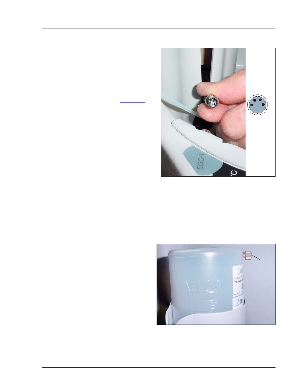
13. Remove the plug from
EGC-1 connector on
the
top of the ICS-2100.
14. Orient the cartridge’s
blue 4-pin electrical
cable connector as
shown in Figure 64
Push it onto the
.
EGC-1
connector on the ICS-
2100. Twist the ring on
the cable connector
fingertight to secure it.
Figure 64. Connecting the EluGen Cartridge Cable
Setting Up the Eluent Generator
Connecting the EluGen Cartridge Vent Line
1. Locate the EluGen Cartridge Vent Line Tubing Kit supplied with the
EluGen cartridge.
2. Slide the label onto one end of the tubing and then push the barbed
luer lock onto the tubing.
3. Unscrew and remove
the plug from the vent
opening on the side of
the EluGen cartridge
(see Figure 65
).
Figure 65. EluGen Cartridge Vent Plug
Vent Plug
(remove)
Doc. 065294-01 3/09 63
Page 68

ICS-2100 Installation Instructions
4. Screw the luer adapter
onto the vent opening.
Luer Adapter
Luer Lock
Remove the cap on
the luer adapter by
twisting. Save the
cap.
EGC Vent Line
5. Twist the luer lock
and EluGen cartridge
vent line into the luer
adapter (see
Figure 66
).
Figure 66. Installing the EluGen Cartridge Vent Line
NOTE To prevent leaks from the EluGen cartridge,
always replace the luer adapter cap before
moving the EluGen cartridge.
6. Direct the vent line to the waste container and insert it down into the
waste, gas separator tube about 10 to 15 cm (4 to 6 in).
Installing the EPM
1. Remove the plugs from
EPM
the EPM eluent and
regen liquid ports.
2. Push the EPM onto the
Mounting Bracket
EGC Cable
ball studs on the
mounting bracket (see
Figure 67
64 Doc. 065294-01 3/09
).
Ball Studs
Figure 67. EPM and Mounting Bracket
Page 69

Setting Up the Eluent Generator
3. Lift the EluGen
cartridge up slightly
from the EGC holder
and slide the EPM
bracket onto the side of
EGC Cable
the holder (see
Figure 68
).
Figure 68. EPM and Mounting Bracket Installed on EGC Holder
4. Connect the following lines to the EPM:
• Connect the TO CR-TC/EPM ELUENT OUT line (yellow label) to
the
ELUENT OUT port on the EPM (see Figure 69).
• Connect the TO CR-TC/EPM ELUENT IN line (red label) to the
ELUENT IN port on the EPM.
• Connect the TO CR-TC/EPM REGEN IN line (orange label) to the
REGEN IN port on the EPM.
• Connect the TO CR-TC/EPM REGEN OUT line (blue label) to the
REGEN OUT port on the EPM.
Doc. 065294-01 3/09 65
Page 70
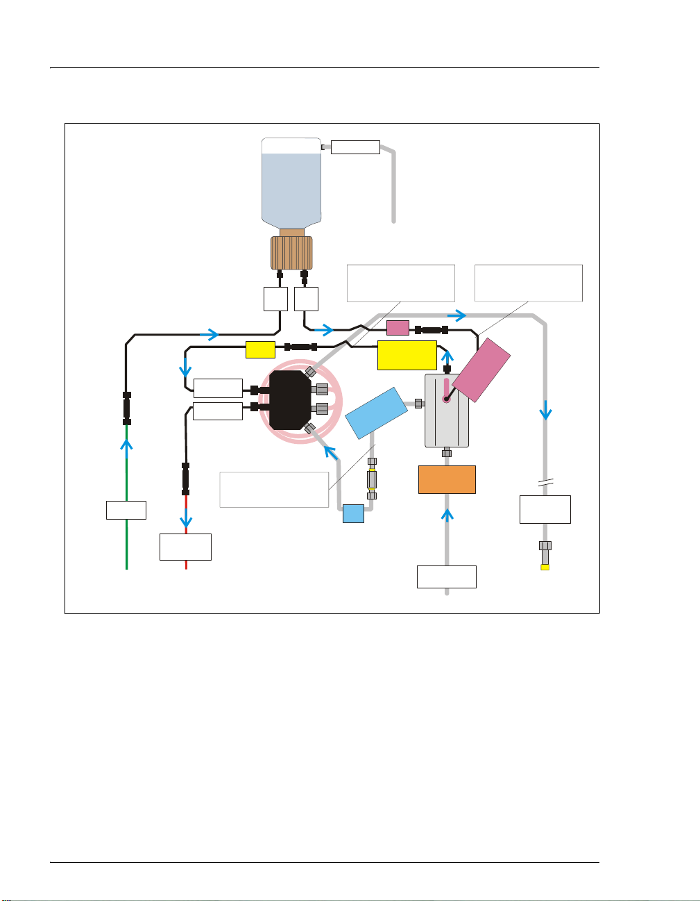
ICS-2100 Installation Instructions
y
EGC II
KCO
23
EGC VENT
Send to waste
TO PUMP/
DAMPER
Pre-plumbed
Pump Pulse
to
Damper
TO DEGAS
ELUENT IN
TO DEGAS
ELUENT OUT
TO INJ
VALVE IN - P/
ELUENT OUT
Pre-plumbed
Inject Valve
to
Port P
Inlet
(yellow
label)
EGC
Outlet
EGC
IN
OUT
EGC
DEGAS
28 cm (11 in) of clear
1.58-mm (0.062-in) ID
Teflon tubing (P/N 064337)
35 cm (14 in) of black
0.25-mm (0.010-in) ID
PEEK tubing (P/N 064340)
(red
label)
TO CR-TC/EPM
ELUENT OUT
(yellow label)
M
P
E
/
T
C
T
U
-
O
R
)
l
C
N
e
E
b
O
a
G
T
l
E
e
R
u
l
b
(
TO CR-TC/EPM
REGEN IN
(orange label)
(blue
label)
TO SRS/AES
REGEN OUT
30 cm (12 in) of black
0.25-mm (0.010-in) ID
PEEK tubing (P/N 064334)
P
E
/
C
T
T
-
N
R
E
C
ELUENT IN
U
d
L
O
e
E
T
r
(
EPM
M
I
a
l
Figure 69. EluGen Cartridge and EPM Plumbing with Tubing Extensions
5. Remove the plug from the EGC-2 connector on top of the ICS-2100.
N
)
l
e
b
WASTE,
GAS
SEPARATOR
Connect to
Gas Separator
Assembl
6. Connect the EPM electrical cable to the
66 Doc. 065294-01 3/09
EGC-2 connector.
Page 71

Setting Up the Eluent Generator
Recording the EluGen Cartridge and EPM Serial Numbers in
Chromeleon
The serial numbers are printed on labels on the EluGen cartridge and
EPM.
1. Open the Server Configuration program (select Start > Programs >
Chromeleon > Server Configuration ).
2. Double-click the ICS-2100 system icon. The properties dialog box for
the ICS-2100 appears.
3. Click the Eluent Generator tab (see Figure 70
).
4. Select the EGC-1 check box and enter the EluGen cartridge serial
number.
5. Select the EGC-2 check box and enter the serial number of the EPM.
6. Click OK.
Figure 70. Eluent Generator Configuration Properties: CO3 / EPM Example
Doc. 065294-01 3/09 67
Page 72

ICS-2100 Installation Instructions
p
Plumbing the EluGen Cartridge and EPM for Conditioning
Figure 71 illustrates the liquid flow path through the EluGen cartridge
and EPM during the conditioning procedure.
EGC II
KCO
23
EGC VENT
Send to waste
TO PUMP/
DAMPER
Pre-plumbed
Pump Pulse
to
Dam
er
ELUENT IN
ELUENT OUT
TO INJ
VALVE IN - P/
ELUENT OUT
TO DEGAS
TO DEGAS
Inlet
EGC
(yellow
label)
14 MPa (2000 psi)
at 1.0 mL/min
EGC
IN
OUT
EGC
DEGAS
Back-
pressure
Coil
Outlet
T
(blue
label)
10-32 to
1/4-28 Coupler
T
-
R
C
E
O
G
E
R
u
l
b
(
(red
label)
TO CR-TC/EPM
ELUENT OUT
(yellow label)
M
P
E
/
T
C
U
O
)
l
N
e
b
a
l
e
TO SRS/AES
REGEN OUT
ELUENT IN
O
T
EPM
TO CR-TC/EPM
REGEN IN
(orange)
M
P
E
/
N
I
l
T
TC
e
-
N
b
R
E
a
l
C
U
d
L
e
E
r
(
Figure 71. EluGen Cartridge and EPM Plumbing for Conditioning with
Carbonate/Bicarbonate Eluent
)
WASTE,
GAS
SEPARATOR
Connect to
Gas Separator
Assembly
68 Doc. 065294-01 3/09
Page 73

Setting Up the Eluent Generator
1. Disconnect the TO INJ VALVE IN - P/ELUENT OUT line from port P (2)
on the injection valve.
2. Use a 10-32 to 10-32 coupler (P/N 042627) to connect the yellow
0.5 mL/min, 7 MPa (1000 psi) backpressure coil (P/N 053765) to the
TO INJ VALVE IN - P/ELUENT OUT line.
3. Connect a 10-32 to 1/4-28 coupler (P/N 042806) to the free end of the
backpressure coil.
TO SRS/AES
REGEN OUT
10-32 to
1/4-28
Coupler
TO INJ
VALVE IN - P/
ELUENT OUT
4. Disconnect the
REGEN OUT port.
5. Connect the
coupler (see Figure 72
TO SRS/AES REGEN OUT line from the suppressor
TO SRS/AES REGEN OUT line to the 10-32 to 1/4-28
).
NOTE The backpressure coil connection in Figure 72 is
temporary; it is required only during the EPM and
EluGen cartridge conditioning procedure described
in the next section.
Backpressure
Coil
10-32 to
10-32
Coupler
Figure 72. Backpressure Coil Connections for Conditioning the
EluGen Cartridge and EPM with Carbonate/Bicarbonate Eluent
Doc. 065294-01 3/09 69
Page 74

ICS-2100 Installation Instructions
Conditioning the EPM and EluGen Cartridge
After completing the plumbing connections described in the previous
sections, follow the steps below to hydrate the EPM for 5 minutes and
then condition the EPM and EluGen cartridge for 30 minutes.
1. Make sure the eluent reservoir is filled with ASTM filtered, Type I
(18-megohm) deionized water.
2. Verify that the suppressor is off.
To avoid damaging the suppressor, always turn off the suppressor
before conditioning the EPM and EluGen cartridge. The pump flow is
on during conditioning, however, no flow reaches the suppressor.
3. Verify that the
selected on the ICS-2100 touch screen
Automatically turn on with pump option is not
SUPPRESSOR page. Disabling
this option lets you turn on the pump, without automatically turning
on the suppressor.
4. On the ICS-2100 touch screen
HOME page, set the pump flow rate to
1.00 mL/min.
5. Turn on the pump.
6. Run the pump for 5 minutes to hydrate the EPM.
7. Touch the
GENERATOR
8. Verify that the cartridge type for
is
pH Mod.
EGC button on the HOME page to open the ELUENT
page.
EGC-1 is Carb and the type for EGC-2
If the cartridge types are wrong, make sure the cartridge serial
numbers were entered correctly in the Chromeleon Server
Configuration program (see “Recording the EluGen Cartridge and
EPM Serial Numbers in Chromeleon” on page 67).
9. Select the following settings:
• Set the EGC-1 concentration to 9mM.
• Set the EGC-2 concentration to 1mM.
10. Turn on the EGC-1 and EGC-2 currents.
11. Run the EluGen cartridge and EPM at these settings for 30 minutes.
70 Doc. 065294-01 3/09
Page 75

Setting Up the Eluent Generator
12. Turn off the EGC-1 and EGC-2 current.
13. Turn off the pump.
Installing the EGC CO3 Mixer
Figure 73 illustrates the EGC CO3 Mixer after installation.
TO EGC CO3
MIXER OUT
(P/N 064343)
TO EGC CO3
MIXER IN
(P/N 064346)
Figure 73. ICS-2100 with an EGC CO3 Mixer Installed
Doc. 065294-01 3/09 71
Page 76

ICS-2100 Installation Instructions
1. Use a Phillips head screwdriver to
remove the existing small diameter
mounting clips from the inside of
the ICS-2100 door.
2. Install the larger diameter clips (P/N
063642) (see Figure 74
Figure 74. Location of Mounting Clips for the EGC CO3 Mixer
3. Orient the mixer with the outlet
pointing upward and push it onto the
clips (see Figure 75
outlet must point upward to ensure
thorough mixing of the eluent.
). The mixer
).
Mixer
Mounting
Clips
Mixer Outlet
4. Locate the 35 cm (14 in) length of
black PEEK tubing (white labels)
(P/N 064346). Connect the end
labeled
TO EGC CO3 MIXER IN to the
mixer inlet.
5. Locate the 60 cm (24 in) length of
black PEEK tubing (white labels)
(P/N 064343). Connect the end
labeled
TO EGC CO3 MIXER OUT to
Mixer Inlet
the mixer outlet.
Figure 75. EGC CO3 Mixer Installed on the ICS-2100 Door
72 Doc. 065294-01 3/09
Page 77

Setting Up the Eluent Generator
Filling the EGC CO
Mixer with Deionized Water
3
1. Verify that the EGC-1 and EGC-2 currents are off.
2. Disconnect the EluGen cartridge inlet line (labeled
PUMP/DAMPER) from the coupler that connects it to the green pump
outlet line (see Figure 76
TO PUMP/
DAMPER
(disconnect
this line)
Pump Outlet
(green
tubing)
).
TO
Figure 76. EluGen Cartridge Inlet and Pump Outlet
Doc. 065294-01 3/09 73
Page 78

ICS-2100 Installation Instructions
3. Connect the pump outlet to the mixer inlet (see Figure 77).
Figure 77. Pump Outlet Connected to Mixer Inlet for Mixer Hydration
4. Direct the mixer outlet line to a temporary waste container, such as a
beaker.
Pump Outlet
Mixer Inlet
5. Verify that the suppressor is off.
To avoid damaging the suppressor, always turn off the suppressor
before filling the mixer. The pump flow is on during filling, however,
no flow reaches the suppressor.
6. Verify that the
selected on the ICS-2100 touch screen
Automatically turn on with pump option is not
SUPPRESSOR page. Disabling
this option lets you turn on the pump, without automatically turning
on the suppressor.
7. Set the pump flow rate to 5.00 mL/min.
8. Turn on the pump.
9. Run the pump until the mixer is filled and there is a consistent flow of
water exiting the mixer outlet.
It takes about 5 minutes to fill a 4-mm mixer and about 2 minutes to
fill a 2-mm mixer.
10. Turn off the pump.
74 Doc. 065294-01 3/09
Page 79

Setting Up the Eluent Generator
V
r
Filling the EGC CO
Mixer with the Carbonate/Bicarbonate Eluent
3
Before initial use, follow the steps in this section to fill the EGC CO3
Mixer with the carbonate/bicarbonate eluent concentration required for
the application to be run.
Figure 78
components during initial filling of the EGC CO
illustrates the liquid flow path through the eluent generator
Mixer with
3
carbonate/bicarbonate eluent.
EGC VENT
EGC II
KCO
23
Send to waste
TO PUMP/
DAMPER
ELUENT OUT
TO INJ
ALVE IN - P/
ELUENT OUT
TO DEGAS
ELUENT IN
TO DEGAS
EGC CO
Inlet
(yellow)
TO EGC CO3
MIXER OUT
Mixer
EGC
3
EGC
IN
EGC
DEGAS
OUT
Outlet
T
(blue)
O
TO CR-TC/EPM
ELUENT OUT
E
/
C
T
-
O
R
C
N
E
G
u
E
l
b
R
(
(red)
(yellow)
M
P
T
U
)
e
TO CR-TC/EPM
ELUENT IN
EPM
REGEN IN
(orange)
M
P
E
/
N
I
T
TC
-
N
)
R
E
d
C
e
U
r
L
(
O
E
T
WASTE,
GAS
SEPARATOR
Pre-plumbed
Pump Pulse
to
Damper
* 14 MPa (2000 psi)
at 1.0 mL/min
Back-
Pressure
Coil*
TO EGC CO3
MIXER IN
TO INJ VALVE
PORT P
TO SRS/AES
REGEN OUT
Connect to
Gas Separato
Assembly
Figure 78. EluGen Cartridge and EPM Plumbing for Initial Filling
of the EGC CO
Doc. 065294-01 3/09 75
Mixer with Carbonate/Bicarbonate Eluent
3
Page 80
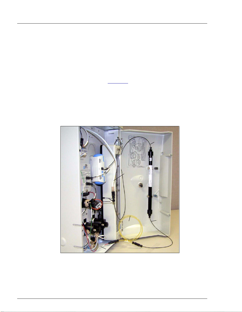
ICS-2100 Installation Instructions
1. Disconnect the pump outlet from the mixer inlet.
2. Reconnect the pump outlet and the EluGen cartridge inlet.
3. Connect a 10-32 to 10-32 coupler to the mixer inlet.
4. Disconnect the outlet of the yellow PEEK backpressure coil from the
TO SRS/AES REGEN OUT line and then connect the backpressure coil
to the mixer inlet (see Figure 79
).
5. Connect the mixer outlet to the
NOTE The backpressure coil connection is temporary;
it is required only during initial filling of the
mixer.
pressure
TO SRS/AES REGEN OUT line.
Mixer Outlet
TO SRS/AES
REGEN OUT
Back-
Coil
Mixer Inlet
TO INJ PORT IN - P/ELUENT OUT
Figure 79. Mixer Connected Directly to Eluent
Generator Outlet for Initial Filling
76 Doc. 065294-01 3/09
Page 81

Setting Up the Eluent Generator
6. Verify that the suppressor is off.
To avoid damaging the suppressor, always turn off the suppressor
before filling the mixer. The pump flow is on during filling, however,
no flow reaches the suppressor.
7. Verify that the
selected on the ICS-2100 touch screen
Automatically turn on with pump option is not
SUPPRESSOR page. Disabling
this option lets you turn on the pump, without automatically turning
on the suppressor.
8. Set the pump flow rate to the rate required for the application.
9. Turn on the pump.
10. Verify that the system backpressure is between 14 and 16 MPa (2000
and 2300 psi). If necessary, adjust the pressure by adding or removing
backpressure tubing.
11. Set the
your application. For example, for a 3.5 mM K
mixture, set the
EGC-1 and EGC-2 concentrations to the values required for
/1.0 mM KHCO3
2CO3
EGC-1 concentration to 3.5 mM and the EGC-2
concentration to 1.0 mM.
12. Turn on the
EGC-1 and EGC-2 currents.
13. Run at the selected settings until the mixer is filled with the eluent
mixture. At a flow rate of 1 mL/min it will take about 45 minutes to
fill the 4-mm mixer and about 15 minutes to fill the 2-mm mixer.
NOTE The void volume of the 4-mm mixer is about
16 mL. The void volume of the 2-mm mixer is
about 5 mL.
14. Turn off the EGC-1 and EGC-2 currents.
15. Turn off the pump.
16. Remove the yellow PEEK backpressure coil from the
IN - P/ELUENT OUT
17. Disconnect the mixer outlet from the
line and the mixer inlet.
TO SRS/AES REGEN OUT line
TO INJ VALVE
and remove the 10-32 to 1/4-28 coupler.
18. Reconnect the
port.
OUT
Doc. 065294-01 3/09 77
TO SRS/AES REGEN OUT line to the suppressor REGEN
Page 82
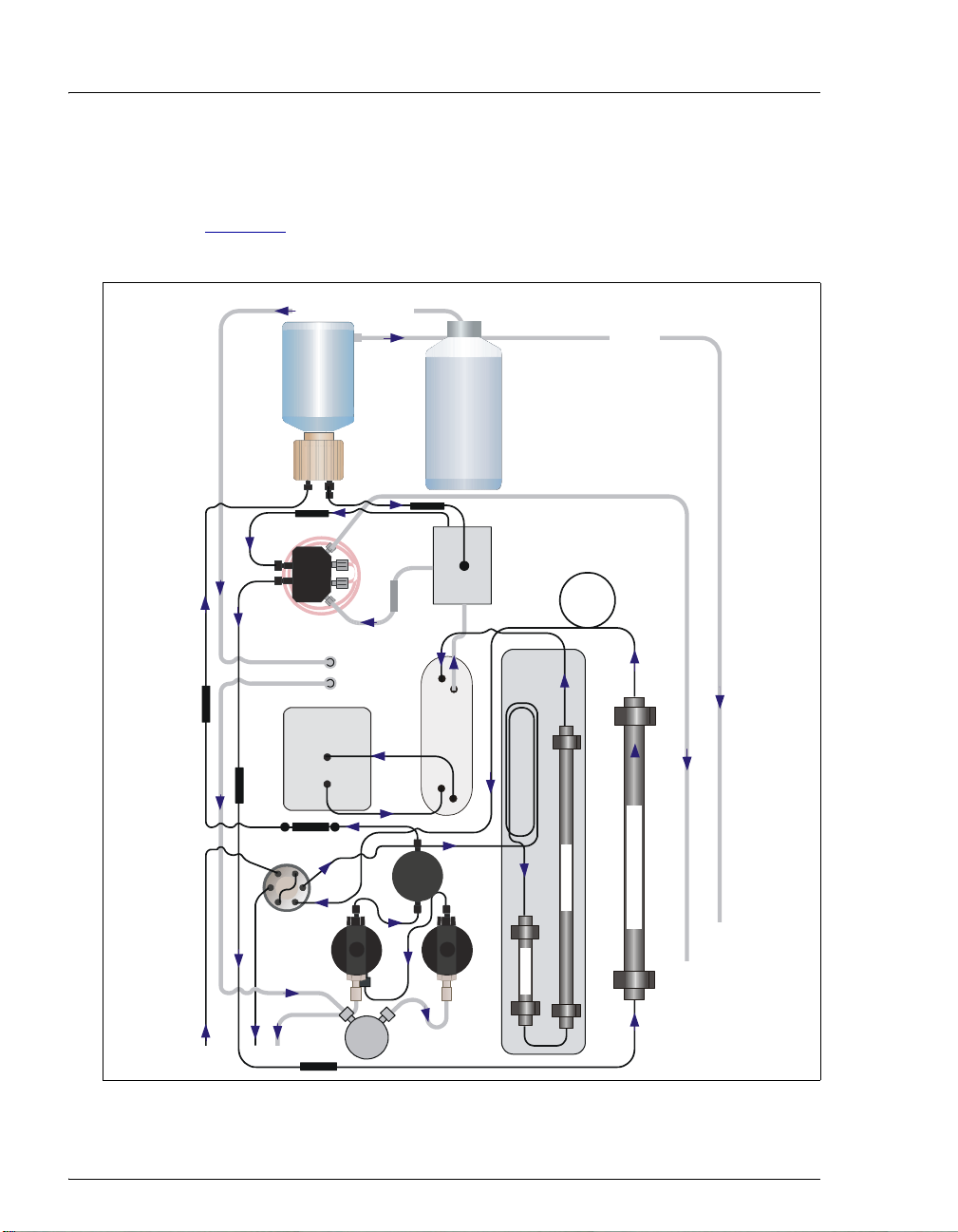
ICS-2100 Installation Instructions
e
Completing the Eluent Generator Setup for Carbonate/Bicarbonate
Eluent
Figure 80 illustrates the liquid flow path through the ICS-2100 after all
setup steps are complete and the eluent generator is ready for operation.
To the pump Degas In
EGC II
K
2CO3
Inlet Outlet
Eluent Out
Deionized
Water
EGC Vent
Cell
Pump
Head
Eluent
Valve
Regen Out
Press.
Xducer.
Eluent In
Suppressor
Regen Out Eluent Out
Pump
Head
EPM
Regen In
Eluent In Regen In
Column
Heater
Heat Exchanger
Guard
Back-
pressure
Coil
Separator
EGC CO
3
Mixer
To wast
To Gas
Separator
Assembly
EGC
Degas
Degas In
Degas Out
Conductivity
Cell In
Cell Out
Pulse Damper
Valve
L
S
C
L
P
Sample in
W
To waste
Figure 80. ICS-2100 Flow Schematic: Carbonate/Bicarbonate Eluent Generation
78 Doc. 065294-01 3/09
Page 83

Setting Up the Eluent Generator
1. Connect the TO INJ VALVE IN - P/ELUENT OUT line to the coupler
attached to the mixer inlet line. Route this line along the back of the
drip tray to prevent it from being pinched when the ICS-2100 door is
opened and closed
2. Route the mixer outlet line to the back of the component panel (see
Figure 81
).
3. Connect the mixer outlet line to port
Figure 81. Mixer Outlet Routed to the Back of the Component Panel
NOTE Backpressure tubing may be required between the
injection valve and the EGC CO
EluGen cartridge requires 14 to 16 MPa (2000 to
2300 psi) of system backpressure for removal of
electrolysis gas from the eluent produced by the
cartridge. See Section 19.1
P (2) on the injection valve.
Mixer outlet. The
3
for details.
4. Go on to Section 19, “Equilibrating the System.”
Doc. 065294-01 3/09 79
Page 84

ICS-2100 Installation Instructions
18.3 Eluent Generator Setup for Carbonate Eluent
Follow the instructions in this section if you are installing a K2CO3
cartridge and an EGC CO
Mixer (for generating carbonate eluent).
3
• If you are installing a KOH, LiOH, MSA, or NaOH EluGen cartridge
and a CR-TC, go to Section 18.1
.
• If you are installing a K
cartridge, an EPM, and an EGC CO
2CO3
3
Mixer (for generating carbonate/bicarbonate eluent), go to
Section 18.2
Overview
.
The eluent generator setup procedure for carbonate eluent consists of the
following main steps:
• Installing the EluGen cartridge and preparing for conditioning.
• Conditioning the EluGen cartridge.
• Installing the EGC CO
• Filling the EGC CO
the application.
Mixer.
3
Mixer with the eluent concentration required for
3
• Completing the eluent generator setup.
80 Doc. 065294-01 3/09
Page 85

Setting Up the Eluent Generator
Items Required to Complete the Setup Procedure
In addition to the EluGen cartridge and the EGC CO3 Mixer, you will
need the following items to complete the eluent generator setup. Except
as noted, all items are supplied in the ICS-2100 Ship Kit (P/N 064375).
Item P/N Use To
Yellow 0.5 mL/min, 7 MPa
(1000 psi) backpressure coil
EluGen Cartridge Vent Line
Tubing Kit (supplied with the
cartridge)
EGC CO
Mixer mounting
3
clips
Phillips head screwdriver (not
supplied)
35 cm (14 in) of black
0.25-mm (0.010-in) ID PEEK
tubing
60 cm (24 in) of black
0.25-mm (0.010-in) ID PEEK
tubing
Temporary waste container
(beaker, bottle, etc.) (not
supplied)
10-32 fittings
10-32 ferrules
1/8-in fittings
1/8-in ferrules
053765 Provide backpressure during
setup procedures.
063092 Vent the cartridge during
operation.
063642 Install the mixer.
n/a Install the EGC CO
Mixer
3
mounting clips.
064346 Connect the EGC degas eluent
outlet and the EGC CO
Mixer
3
inlet.
064343 Connect the EGC CO
outlet to port
P (2) on the
Mixer
3
injection valve.
n/a Collect waste during setup
procedures.
043275
043276
052267
048949
Complete the plumbing
connections.
Complete the plumbing
connections.
10-32 to 10-32 couplers 042627 Complete the plumbing
connections.
Doc. 065294-01 3/09 81
Page 86

ICS-2100 Installation Instructions
r
Figure 82 illustrates the liquid flow path through the eluent generator
components after all setup steps are complete and the eluent generator is
ready for operation.
EGC II
KCO
23
EGC VENT
Send to waste
TO PUMP/
DAMPER
Pre-plumbed
Pump Pulse
to
Damper
TO INJ
VALVE IN - P
ELUENT OUT
TO DEGAS
ELUENT IN
TO DEGAS
ELUENT OUT
EGC CO
Mixer
TO EGC CO3
MIXER IN
Inlet
EGC
Outlet
EGC
OUT
IN
EGC
DEGAS
TO EGC CO3
MIXER OUT
3
Back-
pressure
Coil*
TO INJ VALVE
PORT P
Connect
Inject Valve
to
Port P (2)
*Add backpressure coils, if needed, to
create a system backpressure of between
14 and 16 MPa (2000 and 2300 ps i).
TO SRS/AES
REGEN OUT
Connect to
Suppressor
Regen Out
WASTE,
GAS
SEPARATOR
Connect to
Gas Separato
Assembly
Figure 82. Eluent Generator Flow Schematic with an EGC CO3 Mixer:
Use for Generating Carbonate Eluent
82 Doc. 065294-01 3/09
Page 87

Setting Up the Eluent Generator
r
Installing the EluGen Cartridge and Preparing for Conditioning
Follow the steps in this section to install the EluGen cartridge and prepare
it for conditioning before initial use.
Figure 83
procedure.
illustrates the liquid flow path during the conditioning
EGC VENT
EGC II
KCO
23
Send to waste
IN
EGC
EGC
OUT
Outlet
TO DEGAS
ELUENT IN
TO DEGAS
ELUENT OUT
Inlet
EGC
DEGAS
TO PUM P/
DAMPER
Pre-plumbed
Pump Pulse
to
Damper
TO INJ
VALVE IN - P/
ELUENT OUT
Back-
pressure
Coil
14 MPa (2000 psi)
at 1.0 mL/min
To waste
TO SRS/AES
REGEN OUT
Connect to
Suppressor
Regen Out
SEPARATOR
Connect to
Gas Separato
Figure 83. EluGen Cartridge Plumbing for Conditioning with Carbonate Eluent
Doc. 065294-01 3/09 83
WASTE,
GAS
Assembly
Page 88

ICS-2100 Installation Instructions
1. Orient the EluGen
cartridge with the fittings
facing up and remove the
plugs from the cartridge
INLET and OUTLET
fittings (see Figure 84
2. Set the EluGen cartridge in the service area on top of the ICS-2100
and orient it with the cable toward the EGC holder (see Figure 85
).
INLET
Figure 84. EluGen Cartridge Fitting Plugs
OUTLET
).
EGC Cable
Figure 85. EluGen Cartridge in Service Area
84 Doc. 065294-01 3/09
Page 89
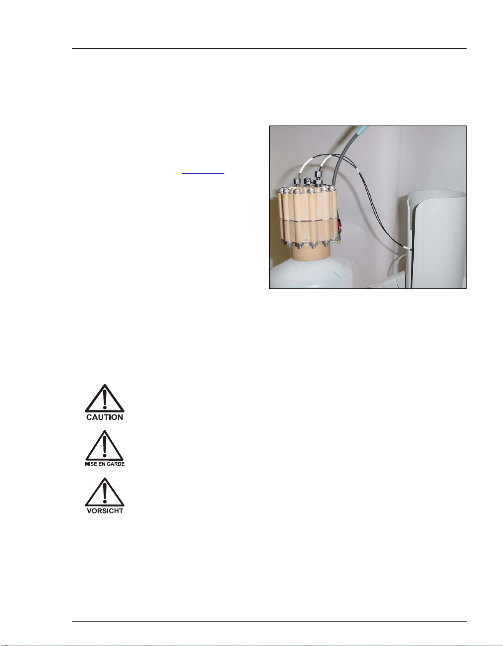
Setting Up the Eluent Generator
3. Pull the coiled black EGC IN and EGC OUT lines out from inside the
EGC holder. Disconnect the
connects it to the
EGC OUT line.
EGC IN line from the coupler that
4. Connect the
EGC IN
line to the EluGen
cartridge
(see Figure 86
INLET port
).
5. Remove the coupler
and connect the
line to the EluGen
OUT
cartridge
EGC
OUTLET port.
Figure 86. EluGen Cartridge Port Connections
6. Turn the EluGen cartridge over (with the fittings facing down). Shake
the EluGen cartridge vigorously , and tap it with the palm of your
hand 10 to 15 times. Check that all bubbles trapped in the eluent
generation chamber are dislodged.
The EluGen cartridge contains one of the following: a corrosive bas e
(KOH, LiOH, or NaOH), a corrosive acid (MSA), or a concentrated
solution. Wear protective eyewear and gloves when handling
K
2CO3
the cartridge.
La cartouche d'EluGen contient un de ce qui suit: un e base corrosive
(KOH, LiOH, ou NaOH), un acide corrosif (MSA), ou une solution
concentrée de K
manipulant la cartouche.
Die EluGen-Kassette enthält eine korrodierende Base (KOH, LiOH
oder NaOH), eine korrodierende Säure (MSA) oder eine konzentrie rte
-Lösung. Tragen Sie daher beim Umgang mit Kassette eine
K
2CO3
Schutzbrille und Handschuhe.
. Porter des lunettes et des gants protectives en
2CO3
Doc. 065294-01 3/09 85
Page 90

ICS-2100 Installation Instructions
7. Slide the EluGen cartridge down into the
holder until it stops (see Figure 87
sure the cable remains out of the holder.
NOTE To avoid crimping the lines, do not
twist the cartridge when you slide
it into the holder. The lines are
designed to coil inside the holder.
Figure 87. EluGen Cartridge Installed in the Holder
8. Remove the plug from
EGC-1 connector on
the
top of the ICS-2100.
). Make
9. Orient the cartridge’s
blue 4-pin electrical
cable connector as
shown in Figure 88
Push it onto the
.
EGC-1
connector on the ICS-
2100. Twist the ring on
the cable connector
fingertight to secure it.
Figure 88. Connecting the EluGen Cartridge Cable
86 Doc. 065294-01 3/09
Page 91
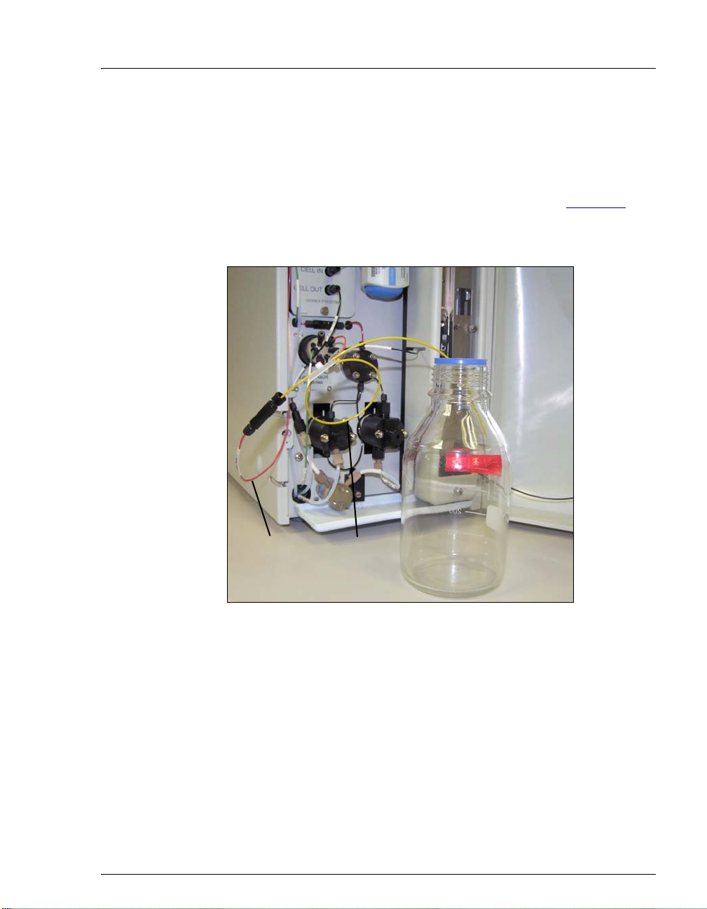
Setting Up the Eluent Generator
10. Disconnect the TO INJ VALVE IN - P/ELUENT OUT line from port P (2)
on the injection valve.
11. Use a 10-32 to 10-32 coupler (P/N 042627) to connect the
VALVE IN - P/ELUENT OUT
line to one end of the yellow 0.5 mL/min,
TO INJ
7 MPa (1000 psi) backpressure coil (P/N 053765) (see Figure 89
12. Direct the free end of the backpressure coil to a temporary waste
container.
EGC Cable
TO INJ V AL VE
IN - P/
ELUENT OUT
Back-
pressure
Coil
Temporary
Waste
Container
).
Figure 89. Plumbing Connections for Conditioning the
EluGen Cartridge with Carbonate Eluent
Installing the EluGen Cartridge Vent Line
1. Locate the EluGen Cartridge Vent Line Tubing Kit
(P/N 063092) supplied with the EluGen cartridge.
2. Slide the label onto one end of the tubing and then push the barbed
luer lock onto the tubing.
Doc. 065294-01 3/09 87
Page 92

ICS-2100 Installation Instructions
3. Unscrew and remove
the plug from the vent
opening on the side of
the EluGen cartridge
(see Figure 90
).
Vent Plug
(remove)
Figure 90. EluGen Cartridge Vent Plug
4. Screw the luer adapter
onto the vent opening.
Luer Adapter
Luer Lock
Remove the cap on
the luer adapter by
twisting. Save the
cap.
EGC
Vent Line
5. Twist the luer lock
and EluGen cartridge
vent line into the luer
adapter (see
Figure 91
NOTE To prevent leaks from the EluGen cartridge, always
).
Figure 91. Installing the EluGen Cartridge Vent Line
replace the luer adapter cap before moving the
EluGen cartridge.
6. Direct the EluGen cartridge vent line to the rear of the ICS-2100 and
snap it onto one of the tubing clips on the rear panel.
7. Direct the vent line to the waste container and insert it down into the
waste, gas separator tube about 10 to 15 cm (4 to 6 in).
88 Doc. 065294-01 3/09
Page 93

Setting Up the Eluent Generator
Recording the EluGen Cartridge Serial Number in Chromeleon
The serial number is printed on the EluGen cartridge label.
1. Open the Chromeleon Server Configuration program (click Start on
the Windows taskbar and select All Programs > Chromeleon >
>Server Configuration).
2. Double-click the ICS-2100 system icon. The properties dialog box for
the ICS-2100 appears.
3. Click the Eluent Generator tab (see Figure 92
).
4. Select the EGC-1 check box.
5. Enter the EluGen cartridge serial number and click OK.
Figure 92. Eluent Generator Configuration Properties: CO3 Example
Doc. 065294-01 3/09 89
Page 94

ICS-2100 Installation Instructions
Conditioning the EluGen Cartridge
After completing the installation steps described in the previous sections,
condition the EluGen cartridge for 30 minutes before initial use.
1. Make sure the eluent reservoir is filled with ASTM filtered, Type I
(18-megohm) deionized water.
2. Verify that the suppressor is off.
To avoid damaging the suppressor, always turn off the suppressor
before conditioning the EluGen cartridge. The pump flow is on during
conditioning, however, no flow reaches the suppressor.
3. Verify that the
selected on the ICS-2100 touch screen
Automatically turn on with pump option is not
SUPPRESSOR page. Disabling
this option lets you turn on the pump, without automatically turning
on the suppressor.
4. On the ICS-2100 touch screen
HOME page, set the pump flow rate to
1.00 mL/min.
5. Turn on the pump.
6. On the touch screen
ELUENT GENERATOR page. Verify that the cartridge type is Carb.
HOME page, touch the EGC button to open the
If the cartridge type is wrong, verify that the cartridge serial number
was entered correctly in the Chromeleon Server Configuration
program (see “Recording the EluGen Cartridge Serial Number in
Chromeleon” on page 89).
7. Set the
EGC-1 concentration to 9mM.
8. Turn on the EGC-1 current.
9. Run the EluGen cartridge at these settings for 30 minutes.
10. Turn off the EGC-1 current.
11. Turn off the pump.
90 Doc. 065294-01 3/09
Page 95

Setting Up the Eluent Generator
Installing the EGC CO
Mixer
3
Figure 93 illustrates the EGC CO3 Mixer after installation.
TO EGC CO3
MIXER OUT
(P/N 064343)
TO EGC CO3
MIXER IN
(P/N 064346)
Figure 93. ICS-2100 with an EGC CO3 Mixer Installed
Doc. 065294-01 3/09 91
Page 96
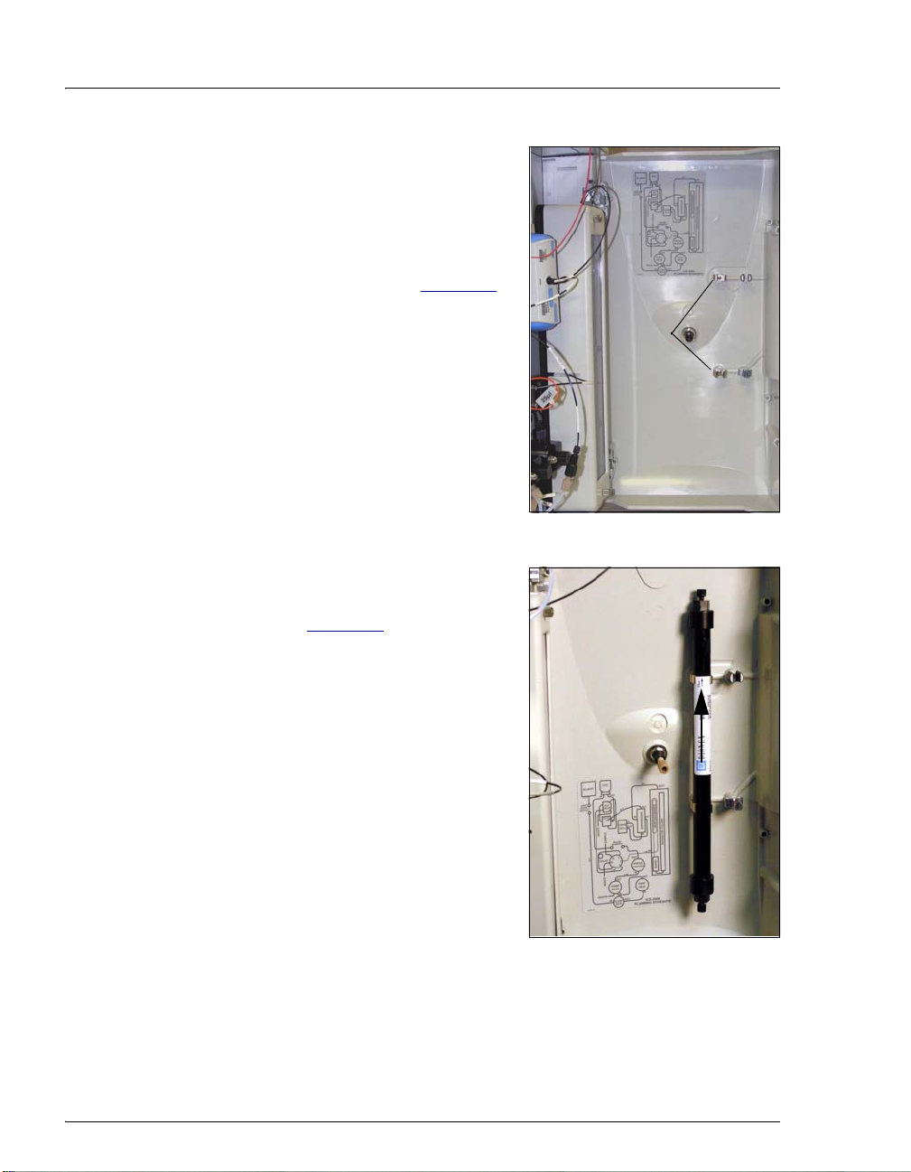
ICS-2100 Installation Instructions
1. Use a Phillips head screwdriver to
remove the existing small diameter
mounting clips from the inside of
the ICS-2100 door.
2. Install the larger diameter mounting
clips (P/N 063642) (see Figure 94
Figure 94. Location of Mounting Clips for the EGC CO3 Mixer
3. Orient the mixer with the outlet
pointing upward and push it onto the
clips (see Figure 95
outlet must point upward to ensure
thorough mixing of the eluent.
). The mixer
).
Mixer
Mounting
Clips
Mixer Outlet
4. Locate the 35 cm (14 in) length of
black PEEK tubing (white labels)
(P/N 064346). Connect the end
labeled
TO EGC CO3 MIXER IN to the
mixer inlet.
5. Locate the 60 cm (24 in) length of
black PEEK tubing (white labels)
(P/N 064343). Connect the end
labeled
TO EGC CO3 MIXER OUT to
Mixer Inlet
the mixer outlet.
Figure 95. EGC CO3 Mixer Installed on the ICS-2100 Door
92 Doc. 065294-01 3/09
Page 97

Setting Up the Eluent Generator
r
y
Filling the EGC CO
Mixer with the Carbonate Eluent
3
Before initial use, follow the steps in this section to fill the EGC CO3
Mixer with the carbonate eluent required for the application to be run.
Figure 96
components during initial filling of the EGC CO
illustrates the liquid flow path through the eluent generator
Mixer with carbonate
3
eluent.
EGC VENT
EGC II
KCO
23
Send to waste
Inlet
EGC
Outlet
EGC
OUT
IN
TO PUMP/
DAMPER
Pre-plumbed
Pump Pulse
to
Damper
TO INJ
VALVE IN - P/
ELUENT OUT
Back-
pressure
Coil
TO DEGAS
ELUENT IN
TO DEGAS
ELUENT OUT
EGC CO
14 MPa (2000 psi)
at 1.0 mL/min
DEGAS
3
Mixer
TO EGC CO3
MIXER IN
EGC
TO EGC CO3
MIXER OUT
To waste
TO SRS/AES
REGEN OUT
Connect to
Suppressor
Regen Out
SEPARATOR
Connect to
Gas Separato
Figure 96. Plumbing for Filling the EGC CO3 Mixer with Carbonate Eluent
Doc. 065294-01 3/09 93
WASTE,
GAS
Assembl
Page 98

ICS-2100 Installation Instructions
1. Connect a 10-32 to 10-32 coupler to the mixer inlet and connect the
outlet of the yellow PEEK backpressure coil to the coupler.
2. Direct the mixer outlet to the temporary waste container.
3. Verify that the suppressor is off.
To avoid damaging the suppressor and CR-TC, always turn off the
suppressor before conditioning the EluGen cartr idge. The pump flow
is on during conditioning, however, no flow reaches the suppressor.
4. Verify that the
selected on the ICS-2100 touch screen
Automatically turn on with pump option is not
SUPPRESSOR page. Disabling
this option lets you turn on the pump, without automatically turning
on the suppressor.
5. Set the pump flow rate to the rate required for the application.
6. Turn on the pump.
7. Verify that the system backpressure is between 14 and 16 MPa (2000
and 2300 psi). If necessary, adjust the pressure by adding or removing
backpressure tubing.
8. Set the
EGC-1 concentration to the value required for your
application.
9. Turn on the
EGC-1 current.
10. Run at these settings until a consistent flow of eluent is exiting the
mixer outlet. At a flow rate of 1 mL/min it will take about 16 minutes
to fill a 4-mm mixer and about 5 minutes to fill a 2-mm mixer.
NOTE The void volume of the 4-mm mixer is about
16 mL. The void volume of the 2-mm mixer is
about 5 mL.
11. Turn off the EGC-1 current.
12. Turn off the pump.
13. Remove the yellow PEEK backpressure coil from the
IN - P/ELUENT OUT
line and the mixer inlet.
TO INJ VALVE
14. Retain the coupler on the mixer inlet.
94 Doc. 065294-01 3/09
Page 99

Setting Up the Eluent Generator
Completing the Eluent Generator Setup for Carbonate Eluent
Figure 97 illustrates the liquid flow path through the ICS-2100 after all
setup steps are complete and the eluent generator is ready for operation.
To the pump Degas In
EGC Vent
EGC II
K
2CO3
Deionized
Water
Inlet Outlet
Sample
in
Valve
S
W
L
To waste
EGC
Degas
Degas In
Degas Out
Conductivity
Cell
Cell In
Cell Out
Pulse Damper
L
C
P
Pump
Head
Eluent
Valve
Press.
Xducer.
Eluent In Regen In
Suppressor
Pump
Head
Regen Out Eluent Out
pressure
Column
Heater
Heat Exchanger
Guard
Back-
Coil
EGC CO
Separator
3
Mixer
To waste
To Gas
Separator
Assembly
Figure 97. ICS-2100 Flow Schematic: Carbonate Eluent Generation
Doc. 065294-01 3/09 95
Page 100
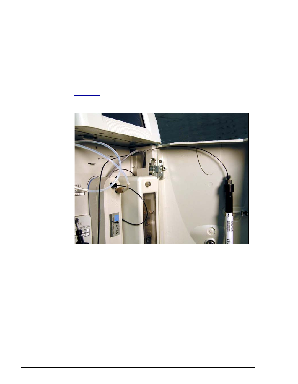
ICS-2100 Installation Instructions
1. Connect the TO INJ VALVE IN - P/ELUENT OUT line to the coupler
attached to the mixer inlet line. Route this line along the back of the
drip tray to prevent it from being pinched when the ICS-2100 door is
opened and closed.
2. Route the mixer outlet line to the back of the component panel (see
Figure 98
).
3. Connect the mixer outlet line to port
Figure 98. Mixer Outlet Routed to the Back of the Component Panel
NOTE Backpressure tubing may be required between the
injection valve and the EGC CO
EluGen cartridge requires 14 to 16 MPa (2000 to
2300 psi) of system backpressure for removal of
electrolysis gas from the eluent produced by the
cartridge. See Section 19.1
P (2) on the injection valve.
Mixer outlet. The
3
for details.
4. Go on to Section 19, “Equilibrating the System.”
96 Doc. 065294-01 3/09
 Loading...