

Page 1

ICS-1000 ION CHROMATOGRAPHY SYSTEM
OPERATOR’S MANUAL
© 2003 Dionex Corporation
Document No. 031879
Revision 01
March 2003
Page 2

©2003 by Dionex Corporation
All rights reserved worldwide.
Printed in the United States of America.
This publication is protected by federal copyright law. No part of this publication
may be copied or distributed, transmitted, transcribed, stored in a retrieval system, or
transmitted into any human or computer language, in any form or by any means,
electronic, mechanical, magnetic, manual, or otherwise, or disclosed to third parties
without the express written permission of Dionex Corporation, 1228 Titan Way,
Sunnyvale, California 94088-3603 U.S.A.
DISCLAIMER OF WARRANTY AND LIMITED WARRANTY
THIS PUBLICATION IS PROVIDED “AS IS” WITHOUT WARRANTY OF
ANY KIND. DIONEX CORPORATION DOES NOT WARRANT,
GUARANTEE, OR MAKE ANY EXPRESS OR IMPLIED
REPRESENTATIONS REGARDING THE USE, OR THE RESULTS OF THE
USE, OF THIS PUBLICATION IN TERMS OF CORRECTNESS, ACCURACY,
RELIABILITY, CURRENTNESS, OR OTHERWISE. FURTHER, DIONEX
CORPORATION RESERVES THE RIGHT TO REVISE THIS PUBLICATION
AND TO MAKE CHANGES FROM TIME TO TIME IN THE CONTENT
HEREINOF WITHOUT OBLIGATION OF DIONEX CORPORATION TO
NOTIFY ANY PERSON OR ORGANIZATION OF SUCH REVISION OR
CHANGES.
TRADEMARKS
MMS™ MicroMembrane™ Suppressor is a trademark of Dionex Corporation.
AES® Atlas Electrolytic Suppressor, Chromeleon®, OnGuard®, and SRS® SelfRegenerating Suppressor are registered trademarks of Dionex Corporation.
Teflon® is a registered trademark of E.I. duPont de Nemours & Co.
Windows® is a registered trademark of Microsoft Corporation.
PRINTING HISTORY
Revision 01, March 2003
Page 3

Contents
1 • Introduction
1.1 Introduction to Ion Chromatography (IC) . . . . . . . . . . . . . . . . . . . . . . .1-1
1.2 Overview of the ICS-1000 . . . . . . . . . . . . . . . . . . . . . . . . . . . . . . . . . . .1-4
1.3 About This Manual . . . . . . . . . . . . . . . . . . . . . . . . . . . . . . . . . . . . . . . .1-5
1.3.1 Safety Messages and Notes . . . . . . . . . . . . . . . . . . . . . . . . . . .1-6
1.3.2 Safety Labels . . . . . . . . . . . . . . . . . . . . . . . . . . . . . . . . . . . . . .1-8
2 • Features
2.1 Operating Features . . . . . . . . . . . . . . . . . . . . . . . . . . . . . . . . . . . . . . . . .2-1
2.1.1 Front Panel . . . . . . . . . . . . . . . . . . . . . . . . . . . . . . . . . . . . . . . .2-1
2.1.2 Top Cover . . . . . . . . . . . . . . . . . . . . . . . . . . . . . . . . . . . . . . . . .2-3
2.1.3 Component Panel . . . . . . . . . . . . . . . . . . . . . . . . . . . . . . . . . . .2-4
2.1.4 Rear Panel . . . . . . . . . . . . . . . . . . . . . . . . . . . . . . . . . . . . . . . . .2-7
2.2 Flow Schematic . . . . . . . . . . . . . . . . . . . . . . . . . . . . . . . . . . . . . . . . . . .2-9
2.3 The Chromeleon Interface . . . . . . . . . . . . . . . . . . . . . . . . . . . . . . . . . .2-11
2.3.1 The Chromeleon Main Window and Browser . . . . . . . . . . . .2-12
2.3.2 The ICS-1000 Control Panels . . . . . . . . . . . . . . . . . . . . . . . . .2-13
2.4 System Component Details . . . . . . . . . . . . . . . . . . . . . . . . . . . . . . . . .2-19
2.4.1 Vacuum Degas Assembly (Optional) . . . . . . . . . . . . . . . . . .2-19
2.4.2 Eluent Valve . . . . . . . . . . . . . . . . . . . . . . . . . . . . . . . . . . . . . .2-21
2.4.3 Pump . . . . . . . . . . . . . . . . . . . . . . . . . . . . . . . . . . . . . . . . . . . .2-21
Doc. 031879-01 3/03 i
Page 4

ICS-1000 Ion Chromatography System
2.4.4 Injection Valve . . . . . . . . . . . . . . . . . . . . . . . . . . . . . . . . . . . 2-24
2.4.5 Column Heater (Optional) . . . . . . . . . . . . . . . . . . . . . . . . . . . 2-26
2.4.6 Suppressor . . . . . . . . . . . . . . . . . . . . . . . . . . . . . . . . . . . . . . . 2-27
2.4.7 DS6 Heated Conductivity Cell . . . . . . . . . . . . . . . . . . . . . . . 2-27
3 • Operation and Maintenance
3.1 Operation Overview . . . . . . . . . . . . . . . . . . . . . . . . . . . . . . . . . . . . . . . 3-1
3.2 Power Up the System . . . . . . . . . . . . . . . . . . . . . . . . . . . . . . . . . . . . . . 3-3
3.3 Start Chromeleon . . . . . . . . . . . . . . . . . . . . . . . . . . . . . . . . . . . . . . . . . 3-4
3.4 Set Up the Eluent Reservoir . . . . . . . . . . . . . . . . . . . . . . . . . . . . . . . . . 3-6
3.4.1 Prepare the Eluent . . . . . . . . . . . . . . . . . . . . . . . . . . . . . . . . . . 3-6
3.4.2 Degas the Eluent . . . . . . . . . . . . . . . . . . . . . . . . . . . . . . . . . . . 3-6
3.4.3 Filter the Eluent . . . . . . . . . . . . . . . . . . . . . . . . . . . . . . . . . . . . 3-7
3.4.4 Fill the Reservoir . . . . . . . . . . . . . . . . . . . . . . . . . . . . . . . . . . . 3-8
3.4.5 Set the Eluent Level . . . . . . . . . . . . . . . . . . . . . . . . . . . . . . . . . 3-8
3.4.6 Connect the Reservoir . . . . . . . . . . . . . . . . . . . . . . . . . . . . . . . 3-8
3.5 Check All Connections . . . . . . . . . . . . . . . . . . . . . . . . . . . . . . . . . . . . . 3-9
3.6 Prime the Pump . . . . . . . . . . . . . . . . . . . . . . . . . . . . . . . . . . . . . . . . . . 3-9
3.7 Set System Operating Conditions . . . . . . . . . . . . . . . . . . . . . . . . . . . . 3-10
3.8 Equilibrate the System and Verify Operational Status . . . . . . . . . . . 3-11
3.9 Prepare Samples . . . . . . . . . . . . . . . . . . . . . . . . . . . . . . . . . . . . . . . . . 3-12
3.9.1 Collecting and Storing Samples . . . . . . . . . . . . . . . . . . . . . . 3-12
3.9.2 Pretreating Samples . . . . . . . . . . . . . . . . . . . . . . . . . . . . . . . . 3-12
3.9.3 Diluting Samples . . . . . . . . . . . . . . . . . . . . . . . . . . . . . . . . . . 3-13
ii Doc. 031879-01 3/03
Page 5

3.10 Loading and Injecting Samples . . . . . . . . . . . . . . . . . . . . . . . . . . . . . .3-14
3.10.1 Loading Samples with a Syringe . . . . . . . . . . . . . . . . . . . . . .3-15
3.10.2 Loading Samples with a Vacuum Syringe . . . . . . . . . . . . . . .3-16
3.10.3 Loading Samples with an Autosampler . . . . . . . . . . . . . . . . .3-16
3.10.4 Injecting Samples . . . . . . . . . . . . . . . . . . . . . . . . . . . . . . . . . .3-17
3.10.5 Example Chromeleon Commands for Loading and Injecting
Samples 3-17
3.11 Process Samples . . . . . . . . . . . . . . . . . . . . . . . . . . . . . . . . . . . . . . . . .3-18
3.11.1 Manual Sample Processing . . . . . . . . . . . . . . . . . . . . . . . . . .3-18
3.11.2 Automatic (Batch) Sample Processing . . . . . . . . . . . . . . . . . .3-19
3.12 Maintenance . . . . . . . . . . . . . . . . . . . . . . . . . . . . . . . . . . . . . . . . . . . .3-21
4 • Troubleshooting
Contents
4.1 Alarms and Error Conditions . . . . . . . . . . . . . . . . . . . . . . . . . . . . . . . . .4-3
4.2 Liquid Leaks . . . . . . . . . . . . . . . . . . . . . . . . . . . . . . . . . . . . . . . . . . . . .4-9
4.3 Pump Difficult to Prime or Loses Prime . . . . . . . . . . . . . . . . . . . . . . .4-11
4.4 Pump Does Not Start . . . . . . . . . . . . . . . . . . . . . . . . . . . . . . . . . . . . . .4-13
4.5 No Flow . . . . . . . . . . . . . . . . . . . . . . . . . . . . . . . . . . . . . . . . . . . . . . . .4-14
4.6 Erratic Flow/Pressure Reading . . . . . . . . . . . . . . . . . . . . . . . . . . . . . .4-15
4.7 Excessive System Backpressure . . . . . . . . . . . . . . . . . . . . . . . . . . . . .4-15
4.8 Peak “Ghosting” . . . . . . . . . . . . . . . . . . . . . . . . . . . . . . . . . . . . . . . . .4-16
4.9 Nonreproducible Peak Height or Retention Time . . . . . . . . . . . . . . . .4-17
4.10 Abnormal Retention Time or Selectivity . . . . . . . . . . . . . . . . . . . . . .4-17
4.11 No Cell Response . . . . . . . . . . . . . . . . . . . . . . . . . . . . . . . . . . . . . . . .4-18
4.12 High Cell Output . . . . . . . . . . . . . . . . . . . . . . . . . . . . . . . . . . . . . . . . .4-18
Doc. 031879-01 3/03 iii
Page 6

ICS-1000 Ion Chromatography System
4.13 Baseline Noise or Drift . . . . . . . . . . . . . . . . . . . . . . . . . . . . . . . . . . . . 4-19
4.14 Vacuum Degas Assembly Does Not Run . . . . . . . . . . . . . . . . . . . . . . 4-20
5•Service
5.1 Diagnostic and Calibration Procedures . . . . . . . . . . . . . . . . . . . . . . . . 5-1
5.1.1 Chromeleon Wellness Panel Overview . . . . . . . . . . . . . . . . . . 5-2
5.1.2 Calibrating the Conductivity Cell . . . . . . . . . . . . . . . . . . . . . . 5-4
5.1.3 Calibrating the Flow Rate . . . . . . . . . . . . . . . . . . . . . . . . . . . . 5-6
5.1.4 Calibrating the Vacuum Degas Assembly . . . . . . . . . . . . . . . . 5-7
5.2 Isolating a Restriction in the Liquid Lines . . . . . . . . . . . . . . . . . . . . . . 5-7
5.3 Replacing Tubing and Fittings . . . . . . . . . . . . . . . . . . . . . . . . . . . . . . . 5-9
5.4 Rebuilding the Injection Valve . . . . . . . . . . . . . . . . . . . . . . . . . . . . . . 5-10
5.5 Cleaning and Replacing the Pump Check Valves . . . . . . . . . . . . . . . 5-11
5.6 Replacing a Pump Piston Seal and Piston Rinse Seal . . . . . . . . . . . . 5-13
5.7 Replacing a Pump Piston . . . . . . . . . . . . . . . . . . . . . . . . . . . . . . . . . . 5-17
5.8 Replacing the Waste Valve or Priming Valve O-Ring . . . . . . . . . . . . 5-18
5.9 Replacing the Conductivity Cell . . . . . . . . . . . . . . . . . . . . . . . . . . . . . 5-20
5.10 Replacing the Suppressor . . . . . . . . . . . . . . . . . . . . . . . . . . . . . . . . . . 5-22
5.11 Replacing the Column Heater . . . . . . . . . . . . . . . . . . . . . . . . . . . . . . . 5-23
5.12 Replacing the Column Heater Heat Exchanger . . . . . . . . . . . . . . . . . 5-25
5.13 Replacing the Eluent Valve . . . . . . . . . . . . . . . . . . . . . . . . . . . . . . . . 5-26
5.14 Replacing the Leak Sensor . . . . . . . . . . . . . . . . . . . . . . . . . . . . . . . . . 5-28
5.15 Priming with Isopropyl Alcohol . . . . . . . . . . . . . . . . . . . . . . . . . . . . . 5-29
5.16 Changing Main Power Fuses . . . . . . . . . . . . . . . . . . . . . . . . . . . . . . . 5-30
iv Doc. 031879-01 3/03
Page 7

A • Specifications
A.1 Electrical . . . . . . . . . . . . . . . . . . . . . . . . . . . . . . . . . . . . . . . . . . . . . . . A-1
A.2 Physical . . . . . . . . . . . . . . . . . . . . . . . . . . . . . . . . . . . . . . . . . . . . . . . . A-1
A.3 Environmental . . . . . . . . . . . . . . . . . . . . . . . . . . . . . . . . . . . . . . . . . . . A-1
A.4 Front Panel . . . . . . . . . . . . . . . . . . . . . . . . . . . . . . . . . . . . . . . . . . . . . . A-2
A.5 Pump . . . . . . . . . . . . . . . . . . . . . . . . . . . . . . . . . . . . . . . . . . . . . . . . . . A-2
A.6 Detector . . . . . . . . . . . . . . . . . . . . . . . . . . . . . . . . . . . . . . . . . . . . . . . . A-3
A.7 Conductivity Cell with Heat Exchanger . . . . . . . . . . . . . . . . . . . . . . . A-3
A.8 Injection Valve . . . . . . . . . . . . . . . . . . . . . . . . . . . . . . . . . . . . . . . . . . A-3
A.9 Vacuum Degas Assembly (Optional) . . . . . . . . . . . . . . . . . . . . . . . . . A-3
A.10 Column Heater (Optional) . . . . . . . . . . . . . . . . . . . . . . . . . . . . . . . . . . A-4
Contents
B • Installation
B.1 Facility Requirements . . . . . . . . . . . . . . . . . . . . . . . . . . . . . . . . . . . . . B-1
B.2 Unpacking the ICS-1000 System . . . . . . . . . . . . . . . . . . . . . . . . . . . . B-2
B.2.1 Unpacking the Computer (North America only). . . . . . . . . . . B-4
B.2.2 Unpacking the Computer (outside North America) . . . . . . . . B-4
B.3 Installing Chromeleon . . . . . . . . . . . . . . . . . . . . . . . . . . . . . . . . . . . . . B-5
B.4 Installing the Chromeleon Software License . . . . . . . . . . . . . . . . . . . B-6
B.5 Connecting the ICS-1000 to the Chromeleon PC . . . . . . . . . . . . . . . . B-9
B.5.1 Connecting the ICS-1000 to the PC . . . . . . . . . . . . . . . . . . . . B-9
B.5.2 Connecting Additional USB Devices . . . . . . . . . . . . . . . . . . B-10
B.6 Connecting the Power Cord . . . . . . . . . . . . . . . . . . . . . . . . . . . . . . . . B-11
B.7 Turning On the ICS-1000 Power . . . . . . . . . . . . . . . . . . . . . . . . . . . . B-12
Doc. 031879-01 3/03 v
Page 8

ICS-1000 Ion Chromatography System
B.8 Setting Up Chromeleon . . . . . . . . . . . . . . . . . . . . . . . . . . . . . . . . . . . B-13
B.8.1 Assigning the ICS-1000 to a Timebase . . . . . . . . . . . . . . . . .B-13
B.8.2 Assigning DX-LAN Devices to the Timebase (Optional) . . . B-16
B.9 Installing and Plumbing the Columns and Suppressor . . . . . . . . . . . .B-19
B.9.1 Column Heater Setup (Optional) . . . . . . . . . . . . . . . . . . . . . .B-19
B.9.2 Installing the Columns . . . . . . . . . . . . . . . . . . . . . . . . . . . . . .B-20
B.9.3 Installing the Suppressor . . . . . . . . . . . . . . . . . . . . . . . . . . . .B-21
B.10 Connecting the Waste Lines . . . . . . . . . . . . . . . . . . . . . . . . . . . . . . . .B-23
B.10.1 Installing the Gas Separator Waste Tube . . . . . . . . . . . . . . . .B-23
B.11 Setting Up the Eluent Reservoir . . . . . . . . . . . . . . . . . . . . . . . . . . . . .B-25
B.12 Setting Up a Chromeleon Application . . . . . . . . . . . . . . . . . . . . . . . . B-26
B.12.1 Verifying Chromeleon Communication. . . . . . . . . . . . . . . . .B-35
B.13 Setting the Eluent Level . . . . . . . . . . . . . . . . . . . . . . . . . . . . . . . . . . . B-35
B.14 Priming the Pump . . . . . . . . . . . . . . . . . . . . . . . . . . . . . . . . . . . . . . . .B-36
B.14.1 Priming the Eluent Lines with a Syringe . . . . . . . . . . . . . . . .B-36
B.14.2 Priming with the Prime Button. . . . . . . . . . . . . . . . . . . . . . . .B-38
B.15 Equilibrating the System . . . . . . . . . . . . . . . . . . . . . . . . . . . . . . . . . . B-39
B.16 Verifying Operational Status . . . . . . . . . . . . . . . . . . . . . . . . . . . . . . .B-39
B.17 Connecting an AS50 Autosampler (Optional) . . . . . . . . . . . . . . . . . .B-40
B.17.1 AS50 Configuration Requirements . . . . . . . . . . . . . . . . . . . .B-40
B.17.2 AS50 Connections . . . . . . . . . . . . . . . . . . . . . . . . . . . . . . . . .B-41
B.17.3 Enable AS50 Control of the Injection Valve . . . . . . . . . . . . .B-43
B.18 Connecting an AS40 Automated Sampler (Optional) . . . . . . . . . . . .B-44
B.19 Analog Output Connection (Optional) . . . . . . . . . . . . . . . . . . . . . . . .B-46
B.20 Pressurizing the Eluent Reservoir (Optional) . . . . . . . . . . . . . . . . . . .B-46
vi Doc. 031879-01 3/03
Page 9

B.20.1 Connecting the Gas Source (Optional) . . . . . . . . . . . . . . . . . B-47
B.20.2 Pressurizing the Eluent Reservoir (Optional) . . . . . . . . . . . . B-48
B.21 Pump Continuous Seal Wash Connections (Optional) . . . . . . . . . . . B-49
B.22 Manually Connecting to a Control Panel . . . . . . . . . . . . . . . . . . . . . B-51
B.23 Installation Troubleshooting . . . . . . . . . . . . . . . . . . . . . . . . . . . . . . . B-53
C • TTL and Relay Control
C.1 TTL and Relay Connections . . . . . . . . . . . . . . . . . . . . . . . . . . . . . . . . C-1
C.1.1 Selecting TTL Input Functions and Control Types. . . . . . . . . C-3
C.2 Controlling TTL and Relay Outputs . . . . . . . . . . . . . . . . . . . . . . . . . . C-5
C.3 Example Setup for Stand-Alone Operation . . . . . . . . . . . . . . . . . . . . . C-7
Contents
D • Reordering Information
E•FAQ
E.1 How do I hook up an autosampler? . . . . . . . . . . . . . . . . . . . . . . . . . . . E-1
E.2 How do I print? . . . . . . . . . . . . . . . . . . . . . . . . . . . . . . . . . . . . . . . . . . E-1
E.3 Why are the retention times moving? . . . . . . . . . . . . . . . . . . . . . . . . . E-1
E.4 How do I adjust retention times? . . . . . . . . . . . . . . . . . . . . . . . . . . . . . E-1
E.5 When should I remake standards? . . . . . . . . . . . . . . . . . . . . . . . . . . . . E-2
E.6 When should I remake eluents? . . . . . . . . . . . . . . . . . . . . . . . . . . . . . . E-2
E.7 How do I start Chromeleon? . . . . . . . . . . . . . . . . . . . . . . . . . . . . . . . . E-2
E.8 How do I delete data? . . . . . . . . . . . . . . . . . . . . . . . . . . . . . . . . . . . . . E-2
E.9 How do I back up data? . . . . . . . . . . . . . . . . . . . . . . . . . . . . . . . . . . . . E-2
Doc. 031879-01 3/03 vii
Page 10

ICS-1000 Ion Chromatography System
E.10 How do I shut off the system? . . . . . . . . . . . . . . . . . . . . . . . . . . . . . . . E-2
E.11 How do I store columns? . . . . . . . . . . . . . . . . . . . . . . . . . . . . . . . . . . . E-2
E.12 How do I know when a column is dirty? . . . . . . . . . . . . . . . . . . . . . . .E-3
E.13 How do I clean a column? . . . . . . . . . . . . . . . . . . . . . . . . . . . . . . . . . .E-3
E.14 Why is the conductivity high? . . . . . . . . . . . . . . . . . . . . . . . . . . . . . . . E-3
F • Glossary
viii Doc. 031879-01 3/03
Page 11

1 • Introduction
1.1 Introduction to Ion Chromatography (IC)
The Dionex ICS-1000 Ion Chromatography System (ICS-1000) performs ion
analyses using suppressed or non-suppressed conductivity detection. An ion
chromatography system typically consists of a liquid eluent, a high-pressure
pump, a sample injector, a guard and separator column, a chemical suppressor, a
conductivity cell, and a data collection system.
Before running a sample, the ion chromatography system is calibrated using a
standard solution. By comparing the data obtained from a sample to that obtained
from the known standard, sample ions can be identified and quantitated. The data
collection system, typically a computer running chromatography software,
produces a chromatogram (a plot of the detector output vs. time). The
chromatography software converts each peak in the chromatogram to a sample
concentration and produces a printout of the results.
Doc. 031879-01 3/03 1-1
Page 12

ICS-1000 Ion Chromatography System
n
6
A typical IC analysis consists of 6 stages (see Figure 1-1).
. Data Analysis
Conductivity
Cell
Suppressor
5. Detectio
1. Eluent
Eluent
Delivery
Pump
2. Sample
Injection
Figure 1-1. Ion Analysis Process
1. Eluent Delivery
• Eluent, a liquid that helps to separate the sample ions, carries the
sample through the ion chromatography system. The ICS-1000 is an
isocratic delivery system. This means that the eluent composition and
concentration remain constant throughout the run.
2. Sample Injection
• The liquid sample is loaded into a sample loop either manually or
automatically (if an automated sampler is installed). When triggered,
the ICS-1000 injects the sample into the eluent stream.
Injection
Val ve
Guard Column
Sample Loop
Separator
Column
4. Suppression
3. Separation
Sample
• The pump pushes the eluent and sample through the guard and
separator columns (chemically-inert tubes packed with a polymeric
resin). The guard column removes contaminants that might poison the
separator column.
1-2 Doc. 031879-01 3/03
Page 13

3. Separation
• As the eluent and sample are pumped through the separator column,
the sample ions are separated. In the ICS-1000, the mode of
separation is called ion exchange. This is based on the premise that
different sample ions migrate through the IC column at different rates,
depending upon their interactions with the ion exchange sites.
4. Suppression
• After the eluent and sample ions leave the column, they flow through
a suppressor that selectively enhances detection of the sample ions
while suppressing the conductivity of the eluent.
5. Detection
• A conductivity cell measures the electrical conductance of the sample
ions as they emerge from the suppressor and produces a signal based
on a chemical or physical property of the analyte.
6. Data Analysis
• The conductivity cell transmits the signal to a data collection system.
1 • Introduction
• The data collection system (for the ICS-1000, this is Chromeleon®)
identifies the ions based on retention time, and quantifies each analyte
by integrating the peak area or peak height. The data is quantitated by
comparing the sample peaks in a chromatogram to those produced
from a standard solution. The results are displayed as a chromatogram
and the concentrations of ionic analytes can be automatically
determined and tabulated.
Doc. 031879-01 3/03 1-3
Page 14

ICS-1000 Ion Chromatography System
1.2 Overview of the ICS-1000
The ICS-1000 is an integrated ion chromatography system containing a pump,
injection valve, column heater, and conductivity detector. Other system
components, including a guard column, separator column, and suppressor vary,
depending on the analyses to be performed.
The ICS-1000 can optionally be configured with a column heater for temperature
control of the column.
ICS-1000 operation is controlled remotely by a personal computer running
Windows
later). Chromeleon also provides data acquisition and data processing functions.
For communication between the ICS-1000 and Chromeleon, the ICS-1000 is
connected to a USB (Universal Serial Bus) port on the computer or a USB hub.
For installation instructions, see Section B.5
Chromeleon IC System (Document No. 031883).
® 2000 or Windows XP and Chromeleon software (version 6.5 SP2 or
and also refer to Installing the
1-4 Doc. 031879-01 3/03
Page 15

1.3 About This Manual
1 • Introduction
Chapter 1
Introduction
Chapter 2
Features
Overview
Chapter 3
Operation and
Maintenance
Chapter 4
Troubleshooting
Chapter 5
Service
Appendix A
Specifications
Appendix B
Installation
Appendix C
TTL and Relay
Control
Introduces ion analysis and the ICS-1000; explains the
conventions used in this manual, including safety-related
information.
Provides an overview of ICS-1000 operating features and
system components; introduces the Chromeleon user
interface.
Provides operating instructions and describes routine
preventive maintenance procedures.
Lists problems and presents step-by-step procedures for
how to isolate and eliminate the cause of each problem.
Provides step-by-step instructions for routine service and
parts replacement procedures that the user can perform.
Lists the ICS-1000 specifications and installation site
requirements.
Describes how to install the ICS-1000.
Describes the ICS-1000 TTL and relay control features.
Appendix D
Reordering
Information
Appendix E
FAQ
Appendix F
Glossary
Doc. 031879-01 3/03 1-5
Lists spare parts for the ICS-1000.
Provides answers to frequently asked questions about
ICS-1000 operation.
Defines terms commonly used in ion analysis.
Page 16
ICS-1000 Ion Chromatography System
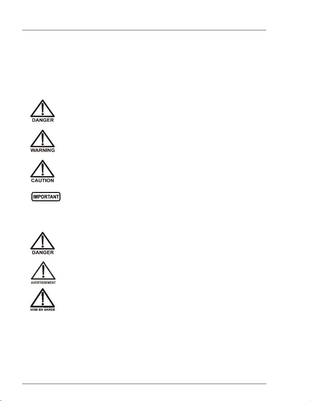
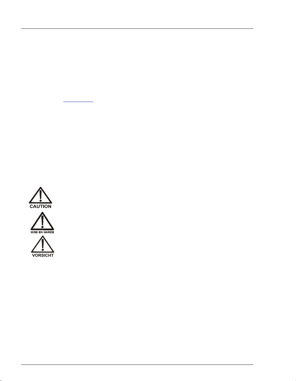
1.3.1 Safety Messages and Notes
This manual contains warnings and precautionary statements that can
prevent personal injury and/or damage to the ICS-1000 when properly
followed. Safety messages appear in bold type and are accompanied by
icons, as shown below.
Indicates an imminently hazardous situation which, if not avoided, will
result in death or serious injury.
Indicates a potentially hazardous situation which, if not avoided,
could result in death or serious injury.
Indicates a potentially hazardous situation which, if not avoided, may
result in minor or moderate injury. Also used to identify a situation or
practice that may seriously damage the instrument, but will not cause
injury.
Indicates that the function or process of the instrument may be
impaired. Operation does not constitute a hazard.
Messages d'avertissement en français
Signale une situation de danger immédiat qui, si elle n'est pas évitée,
entraînera des blessures graves à mortelles.
Signale une situation de danger potentiel qui, si elle n'est pas évitée,
pourrait entraîner des blessures graves à mortelles.
Signale une situation de danger potentiel qui, si elle n'est pas évitée,
pourrait entraîner des blessures mineures à modérées. Également
utilisé pour signaler une situation ou une pratique qui pourrait
gravement endommager l'instrument mais qui n'entraînera pas de
blessures.
1-6 Doc. 031879-01 3/03
Page 17
1 • Introduction
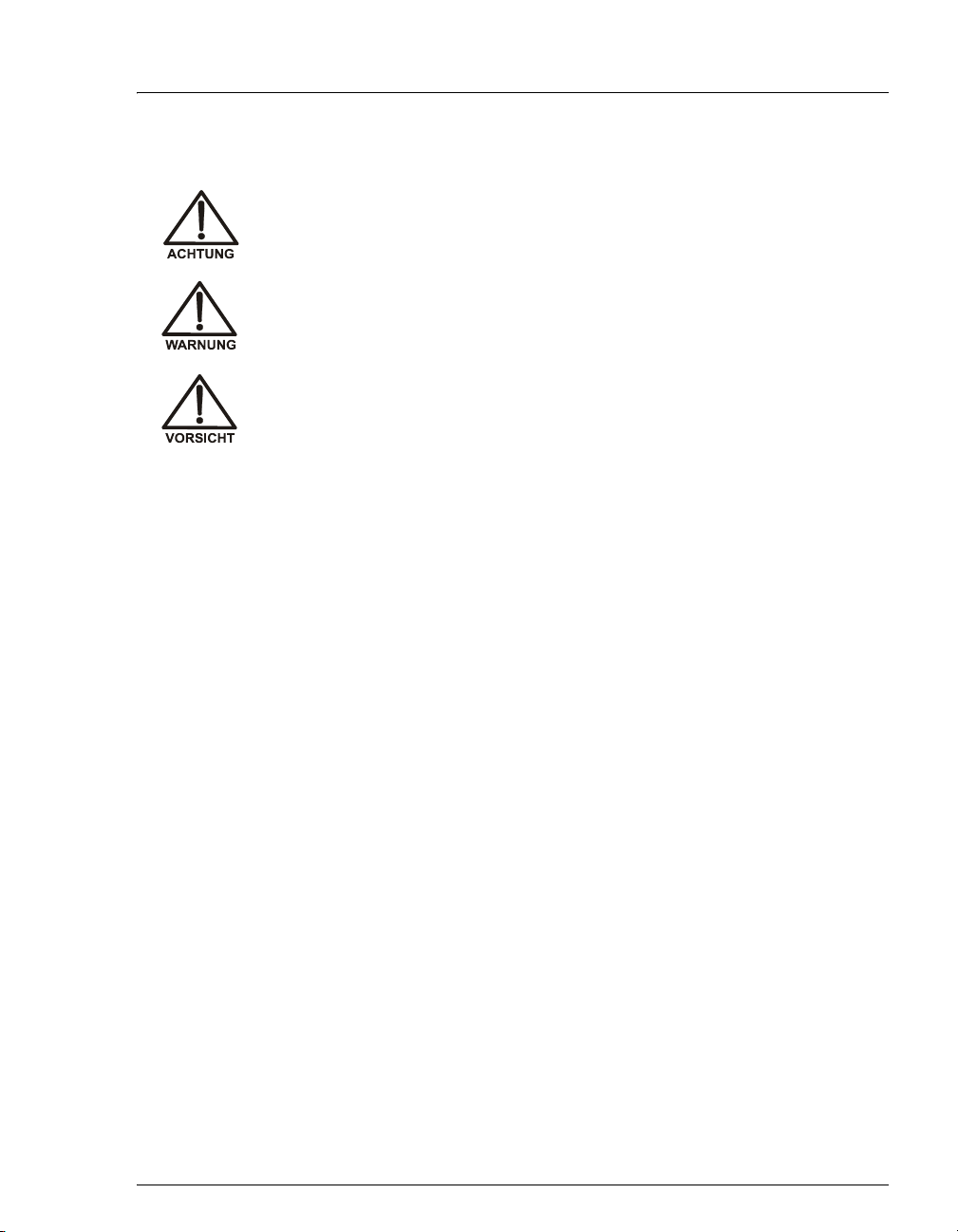
Warnhinweise in Deutsch
Bedeutet unmittelbare Gefahr. Mißachtung kann zum Tod oder
schwerwiegenden Verletzungen führen.
Bedeutet eine mögliche Gefährdung. Mißachtung kann zum Tod oder
schwerwiegenden Verletzungen führen.
Bedeutet eine mögliche Gefährdung. Mißachtung kann zu kleineren
oder mittelschweren Verletzungen führen. Wird auch verwendet, wenn
eine Situation zu schweren Schäden am Gerät führen kann, jedoch
keine Verletzungsgefahr besteht.
Notes
Informational messages also appear throughout this manual. These are
labeled NOTE and are in bold type:
NOTE NOTES call attention to certain information. They alert
you to an unexpected result of an action, suggest how to
optimize instrument performance, etc.
Doc. 031879-01 3/03 1-7
Page 18

ICS-1000 Ion Chromatography System
1.3.2 Safety Labels
The ICS-1000 meets EN 61010-1:1993 (safety), CAN/CSA-C22.2 No.
1010.1-92 (safety), UL 3101-1/10.93 (safety), EN 50082-1:1992
(susceptibility), EN 55011:1991 (emissions). The TUV GS, C, US Mark
safety labels and the CE Mark label on the ICS-1000 attest to compliance
with these standards.
The symbols below appear on the ICS-1000 or on ICS-1000 labels.
Alternating current
Protective conductor terminal (earth ground)
Power supply is on
Power supply is off
1-8 Doc. 031879-01 3/03
Page 19
This chapter describes key ICS-1000 features and introduces the Chromeleon user
interface.
2.1 Operating Features
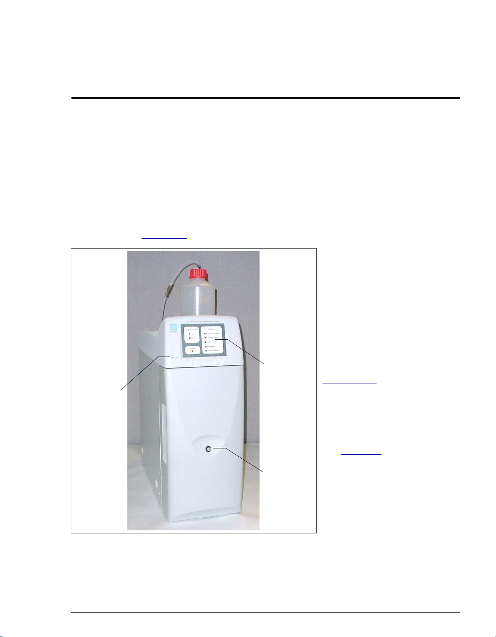
2.1.1 Front Panel
Figure 2-1 illustrates the front panel of the ICS-1000.
Power
LED
Status
LEDs
Injection
Port
2•Features
Injection Port
The sample to be analyzed can
be injected manually into the
injection port, using a syringe.
For automated sample
injection, the ICS-1000 must be
connected to an autosampler.
For more information about
sample injection, see
Section 3.10
LEDs
The status LEDs (see
Figure 2-2
of various system functions.
See Table 2- 1
of each LEDs function. The
power LED indicates whether
the ICS-1000 power is on.
.
) indicate the status
for a description
Figure 2-1. ICS-1000 Front Panel
Doc. 031879-01 3/03 2-1
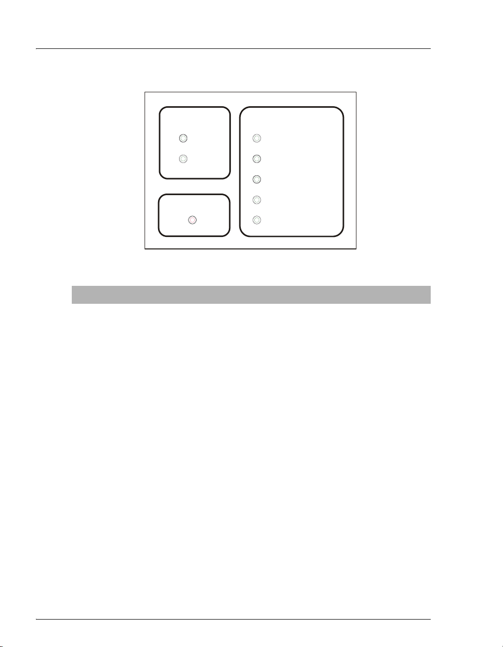
Page 20
ICS-1000 Ion Chromatography System
INJECT VALVE
Load
Inject
ALARM
STATUS
Module Connected
Acquiring Data
Pump
Suppressor
Column Heater
Figure 2-2. Status LEDs
LED Label If On (Green) If Flashing
Load
Injection valve is in Load
Valve error.
position.
Inject
Injection valve is in Inject
Valve error.
position.
Alarm
No “on” (green) state. Error detected. Check the Chromeleon
Audit Trail for the cause.
Module
Connected
ICS-1000 is connected to
a Chromeleon timebase.
Does not flash.
Acquiring
Data
Pump
Sequence or manual data
Sequence has stopped due to an error.
acquisition is in progress.
Pump is on. High or low pressure limit is exceeded.
The pump is turned off
Suppressor
Column
Heater
Suppressor is on and
current is being applied to
it.
Column heater is at set
temperature.
Continuity check failed or suppressor is
over the voltage, current, or power limit.
The suppressor is turned off
Column heater is transitioning to a new
temperature.
Table 2-1. ICS-1000 Status LED States
2-2 Doc. 031879-01 3/03
Page 21
2.1.2 Top Cover
Figure 2-3 illustrates the top cover of the ICS-1000.
Figure 2-3. ICS-1000 (Top View)
2 • Features
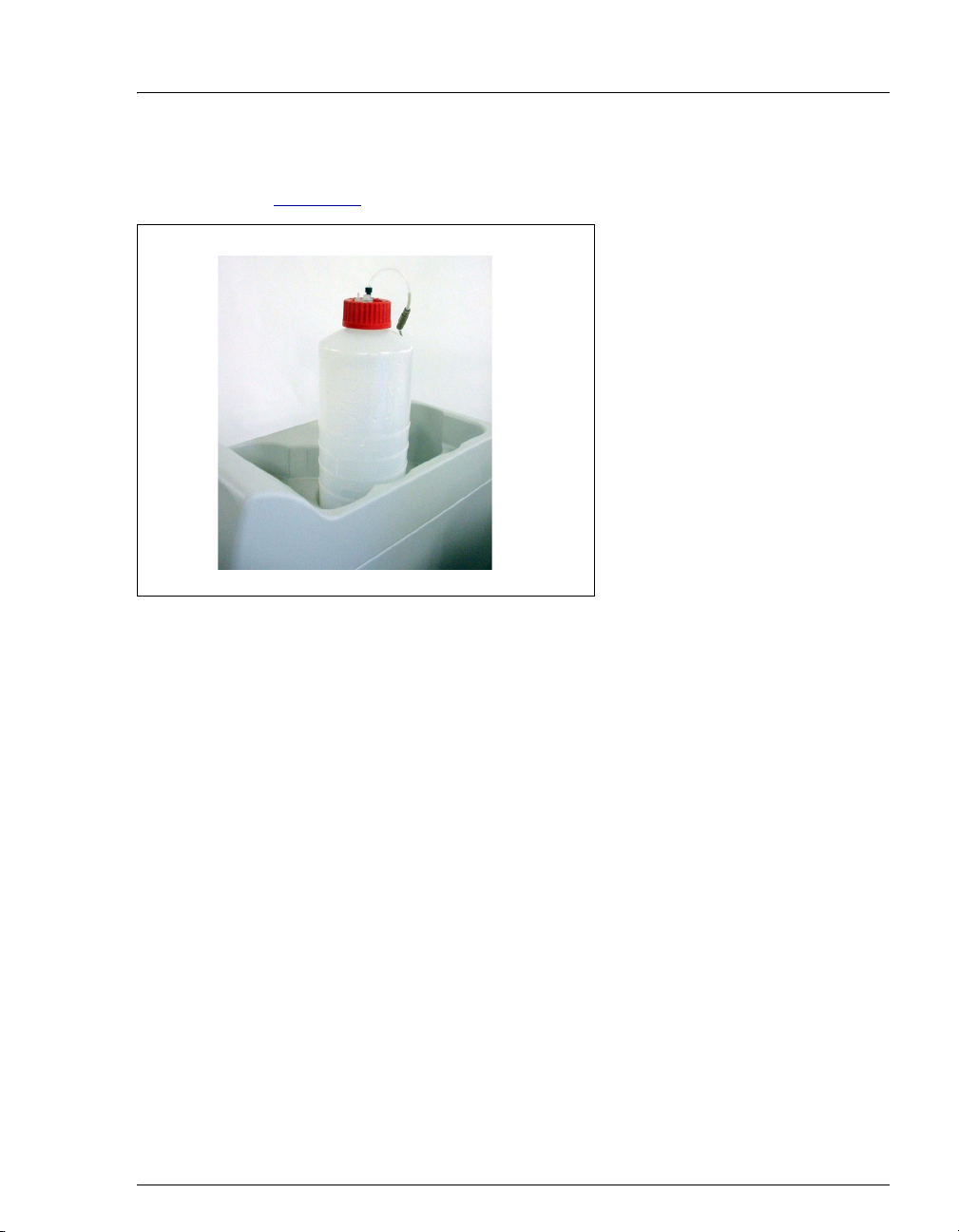
Reservoir Storage
The ICS-1000 top cover has room
for up to three 2-L plastic
reservoirs (P/N 044129).
Tubing Chase
The tubing chase under the top
cover routes tubing to the front of
the ICS-1000.
Doc. 031879-01 3/03 2-3
Page 22
ICS-1000 Ion Chromatography System
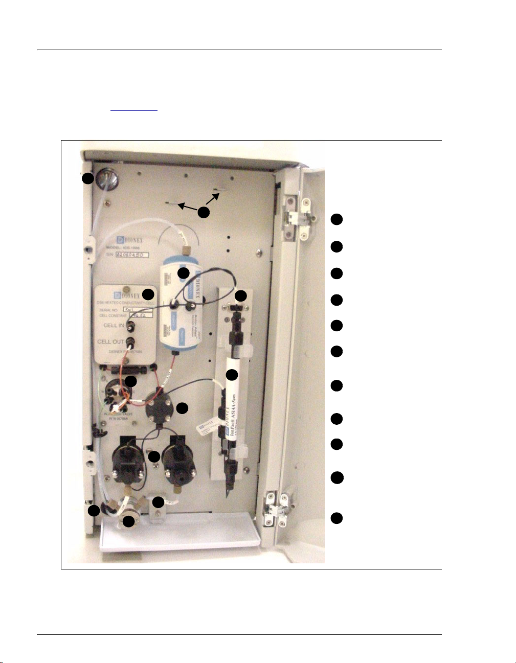
2.1.3 Component Panel
Figure 2-4 shows the user-accessible components installed on the
component panel behind the ICS-1000 front door.
11
11
10
8
9
5
7
6
Eluent Valve
1
Leak Sensor
2
Pump Heads
3
Pressure Transducer
4
Injection Valve
5
6
Columns
Connector for
7
optional column
heater
4
Suppressor
8
DS6 Conductivity
9
3
Cell
Mounting brackets
10
for a second
suppressor
2
Tubing Chase (2)
1
11
Figure 2-4. ICS-1000 Component Panel
2-4 Doc. 031879-01 3/03
Page 23

2 • Features
Eluent Valve
The eluent valve controls the flow from the eluent reservoir. It opens
automatically when the pump is running and closes when the pump is off.
Leak Sensor
The leak sensor is installed in the drip tray at the bottom of the component
panel. If liquid accumulates in the tray, an error message is reported in
Chromeleon and the Alarm LED flashes.
Pump Heads
The ICS-1000 includes a serial isocratic dual-head pump. The flow rate
can be set to 0.00 and to between 0.05 and 5.0 mL/min. However, for
optimum performance, set the flow rate to between 0.4 and 2.0 mL/min.
Setting the flow rate to 0.00 turns off the pump. See Section 2.4.3
details about the pump.
Pressure Transducer
The pressure transducer measures the system backpressure.
for
Injection Valve
The injection valve is a six-port, electrically-activated valve. A 25-µL
sample loop (P/N 042857) is installed on the valve at the factory. See
Section 2.4.4
Separator and Guard Columns
for details about valve operation.
Both the separator and guard columns are packed with resin and perform
the separation of the sample ions. The main function of the guard column
is to trap contaminants and remove particulates that might damage the
separator column.
Column Heater (Optional—Not Pictured)
The column heater controls the temperature of the separator and guard
columns. The temperature can be set to between 30 °C and 60 °C and it
must be set at least 5 °C above the ambient temperature. See Section 2.4.5
for details about the column heater.
Doc. 031879-01 3/03 2-5
Page 24

ICS-1000 Ion Chromatography System
Suppressor
The suppressor reduces the eluent conductivity and enhances the
conductivity of the sample ions, thereby increasing detection sensitivity.
Either an AES® Atlas Electrolytic Suppressor, SRS® Self-Regenerating
Suppressor, or MMS™ MicroMembrane™ Suppressor can be used with
the ICS-1000. See Section 2.4.6
DS6 Heated Conductivity Cell
The flow-through conductivity cell measures the electrical conductance
of analyte ions as they pass through the cell. A heat exchanger inside the
cell regulates the temperature, which can be set to between 30 °C and
55 °C. For optimum performance, set the temperature to at least 7 °C
above the ambient temperature. See Section 2.4.7
cell.
Tubing Chases
The upper tubing chase routes tubing from the top cover to the component
panel. The lower tubing chase routes tubing from the component panel
through the ICS-1000 interior to the rear panel.
for details.
for details about the
2-6 Doc. 031879-01 3/03
Page 25
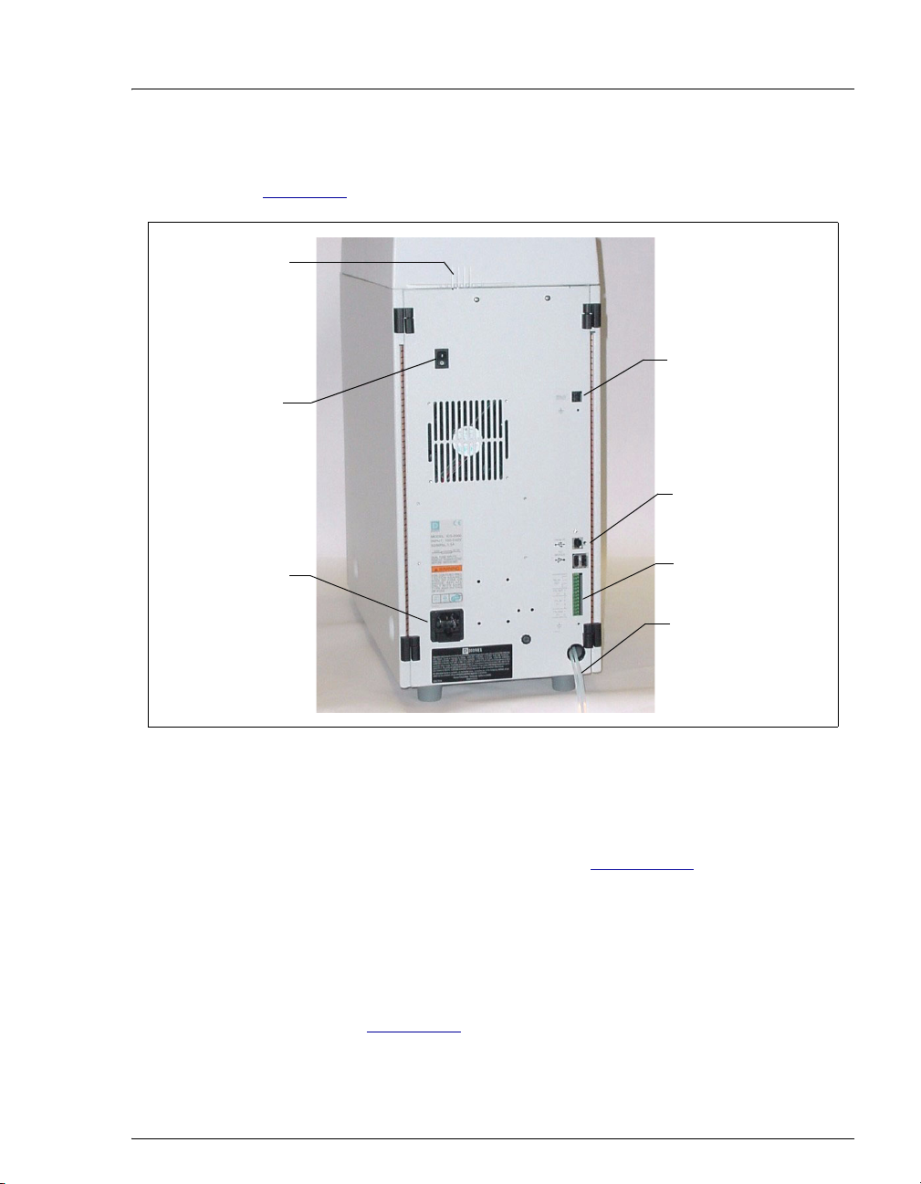
2.1.4 Rear Panel
Figure 2-5 illustrates the ICS-1000 rear panel.
Tubing Clips
Power
Switch
2 • Features
Analog Output Connector
USB Connections
Main Power
Receptacle
Analog Output Connector
The analog output connector outputs conductivity data (scaled to 1 volt)
to an integrator or recording device. See Section B.19
setup information.
USB Connections
A USB receptacle is provided to allow connection to the Chromeleon
computer. Two USB ports are provided for connecting to other USB
devices. See Section B.5
TTL and Relay
Connector Strip
Waste Lines
Figure 2-5. ICS-1000 Rear Panel
for connection and
for connection instructions.
Doc. 031879-01 3/03 2-7
Page 26
ICS-1000 Ion Chromatography System
TTL and Relay Connector
The TTL and Relay connector strip provides two TTL outputs, two relay
outputs, and four TTL inputs. The outputs can be used to control
functions in other TTL or relay controllable devices. The inputs can be
used to switch the injection valve position, turn on the pump, perform an
autozero command, and send an event mark to the analog output. See
Section C.1
Tubing Clips
The tubing clips hold tubing in place when routing it from the top cover.
Power Switch
The power switch provides on/off control of power to the ICS-1000.
Main Power Receptacle
The power supply cord plugs into the AC power receptacle.
The power supply cord is used as the main disconnect device. Make
sure the socket-outlet is located near the ICS-1000 and is easily
accessible.
for connection instructions.
Le cordon d'alimentation principal est utilisé comme dispositif
principal de débranchement. Veillez à ce que la prise de base soit
située/installée près du module et facilement accessible.
Das Netzkabel ist das wichtigste Mittel zur Stromunterbrechung.
Stellen Sie sicher, daß sich die Steckdose nahe am Gerät befindet und
leicht zugänglich ist.
2-8 Doc. 031879-01 3/03
Page 27
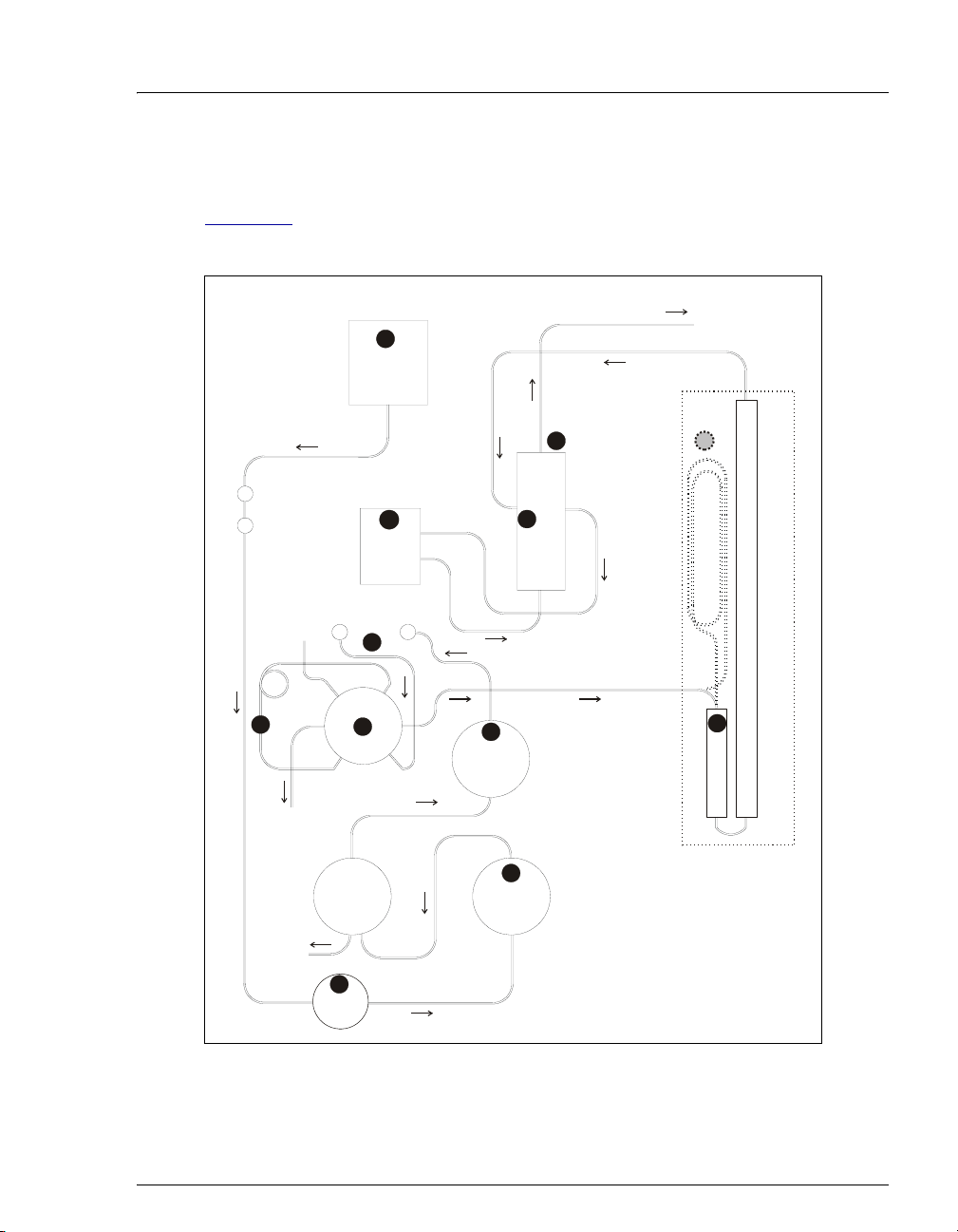
2.2 Flow Schematic
Figure 2-6 illustrates the liquid flow path through an ICS-1000 when using
suppression in autorecycle mode.
2 • Features
PUMP
DEGAS
(Optional)
7
1
ELUENT
OUT
11
IN
COND
OUT
CELL
PULSE
DAMPER
SAMPLE
5
L
S
W
WASTE
C
6
P
L
VALV E
OUT
PUMP PUMP
HEAD
OUT
4
PRESS.
XDUCER
HEAD
WASTE
OUT
12
8
10
SUPPRESSOR
HEAT EXCHANGER
IN
SEPARATOR COLUMN
COLUMN HEATER (optional)
9
GUARD
3
WASTE
IN OUT
ELUENT
VALV E
2
IN
Figure 2-6. ICS-1000 Flow Schematic
Doc. 031879-01 3/03 2-9
Page 28

ICS-1000 Ion Chromatography System
• Eluent from the eluent reservoirn flows first through the pump degas
assembly (if it is installed) and then through the eluent valve
pump
p. It is then pushed through the pressure transducerq, which measures
the system pressure.
• From there, it is pushed through a pulse damperr, which smooths minor
pressure variations from the pump to minimize baseline noise. The eluent then
flows into the injection valve.
s
• After sample is loaded into the sample loopt and the injection valve is
toggled to the Inject position, eluent passes through the sample loop.
• If the optional column heater is installed, the eluent/sample mixture is
pumped through the heat exchanger
heater temperature.
• The mixture then goes to the guard and separator columnsv and through the
suppressor.
w
o to the
u, which heats the mixture to the column
• From the suppressor, the mixture flows through the cell , where the analytes
are detected. A digital signal is sent to Chromeleon software. Analog output
can be collected simultaneously.
11
• Finally, the mixture flows out of the cell and is recycled back into the
suppressor, where it is used as the water source for the regenerant chamber.
Flow is then routed to waste.
12
2-10 Doc. 031879-01 3/03
Page 29

2.3 The Chromeleon Interface
NOTE This section provides a brief overview of the
Chromeleon interface. For details, refer to the
Chromeleon Help or user’s manual.
Chromeleon software is used for remote control of ICS-1000 operation. Two
modes of software control are available: direct control and automated control.
• With direct control, you select operating parameters and commands from the
Chromeleon menu bar, toolbars, and Control Panels. Direct control
commands are executed as soon as they are entered. Section 2.3.2
the commands available from the ICS-1000 Control Panels.
• With automated control, you create a list of samples (a sequence) to be
processed automatically. The sequence includes programs with commands
and parameters for controlling the ICS-1000, acquiring sample data, and
producing reports. Section 3.11.2
describes automatic sample processing.
2 • Features
describes
Doc. 031879-01 3/03 2-11
Page 30
ICS-1000 Ion Chromatography System
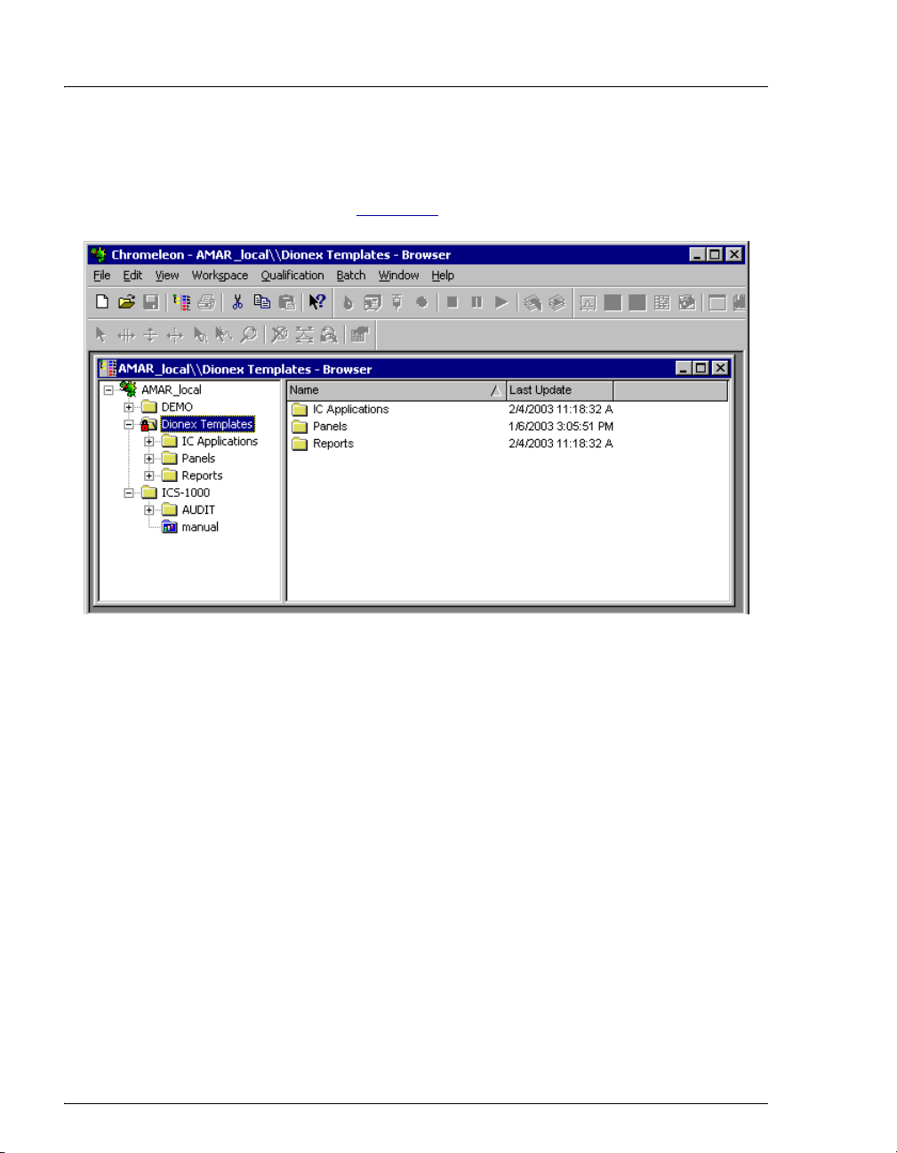
2.3.1 The Chromeleon Main Window and Browser
When you start Chromeleon, the main window and the Chromeleon
Browser appear (see Figure 2-7
).
Figure 2-7. Chromeleon Main Window and Browser
NOTE The Chromeleon Browser looks and functions like
Windows Explorer, but do not confuse the two. If you
copy files from the Chromeleon Browser into Explorer,
the files will be corrupted.
The Browser displays the directories in which chromatographic data is
located, and allows you to open, move, and delete data.
• The left pane of the Browser shows the directory tree structure. By
clicking the ‘+’ signs next to the folders and expanding the directory
tree, you can access sequences, System Control Panels, Wellness
Panels, and reports.
• The right pane displays information about the item selected in the left
pane.
2-12 Doc. 031879-01 3/03
Page 31

2.3.2 The ICS-1000 Control Panels
Chromeleon provides two types of Control Panels for the ICS-1000.
• System Control Panels are used for controlling and monitoring ICS-
1000 operation. System Control Panels are described below.
• The Wellness Panel is used for performing calibration and diagnostic
functions. The Wellness Panel is described in Section 5.1
System Control Panels
System Control Panels for the ICS-1000 are located in the Dionex
Templates/Panels/Dionex_IC\ICS-1000 folder. Chromeleon provides
panels for each ICS-1000 system configuration. There are two styles of
panels:
• Traditional system panels (see Figure 2-8) provide controls on a
single window with minimal graphics.
• System panels (see Figure 2-9) provide a more graphical interface
than the traditional style. On these panels, clicking a control often
brings up another window in which you enter a value.
2 • Features
.
When you open a System Control Panel, select a panel that matches your
system configuration and choose the style that you prefer.
Doc. 031879-01 3/03 2-13
Page 32

ICS-1000 Ion Chromatography System
Figure 2-8. ICS-1000 System Control Panel (Traditional)
Figure 2-9. ICS-1000 System Control Panel (Graphical)
2-14 Doc. 031879-01 3/03
Page 33

2 • Features
System Controls Overview
This section provides brief descriptions of the various controls available
on the ICS-1000 System Control Panels.
NOTE The examples are from the traditional style of panel.
Sample
Datasource
Displays the database in which the chromatographic data for the sample
is saved.
Sequence
Displays the sequence in which this sample is included.
Sample
Displays the name of the sample that is running.
Program
Displays the name of the program that is running.
Elapsed Time
Displays the time that has elapsed since the sample analysis began.
Run Time
Displays the total run time.
System
Startup
Starts the pump and suppressor. The flow rate and suppressor current
settings that were in effect at system shutdown (see below) are restored.
Shutdown
Stops the pump and suppressor. The flow rate and suppressor current
settings currently in effect are remembered and will be restored at
system startup (see above).
Doc. 031879-01 3/03 2-15
Page 34

ICS-1000 Ion Chromatography System
Audit Trail
The Audit Trail displays an account of every event that occurs during
ICS-1000 operation. This includes errors, status messages, operational
events, etc.
Pump
Eluent Bottle
The entry field and gauge indicate the level
of liquid (in liters) in the eluent bottle. This
is a user controlled feature. The level must
be entered by the user when the reservoir is
filled. See Section 3.4.4
for details.
Connected
Connects the ICS-1000 to the Chromeleon
Control Panel, enabling communication
between the PC and the module. Clearing
the check box disconnects the ICS-1000
from the PC.
Hold Mode
Indicates when an automatic (batch) run is on hold; pump flow is not
stopped.
Stop Mode
Indicates when an automatic (batch) run is stopped; pump flow is also
stopped.
Flow Rate
Sets the pump flow rate in mL/min.
Pressure
The sliders select the upper and lower pressure limits. The Pressure field
displays the current pressure.
On, Off, Prime
Turn the pump on and off or start the pump priming function.
2-16 Doc. 031879-01 3/03
Page 35

Column Heater (Optional)
Detector
2 • Features
Inject Valve
Displays the current position of the inject
valve. The
position.
Eluent Flow Valve
Displays the current position of the eluent
flow valve. The
select the position.
Set Temp
Sets the temperature of the column heater.
Inject and Load buttons select the
Closed and Open buttons
Connected
Connects the ICS-1000 to the Chromeleon Control Panel, enabling
communication between the PC and the module. Clearing the Connected
check box disconnects the ICS-1000 from the PC.
Autozero
Sets the conductivity to zero.
Ready
Indicates if the detector is ready to begin data acquisition.
Doc. 031879-01 3/03 2-17
Page 36

ICS-1000 Ion Chromatography System
Signal
Displays the offset conductivity.
Data Rate
Sets the rate at which data points are recorded.
Supp. Type
Selects the type of suppressor installed.
SRS Current
Sets the current supplied to the suppressor.
Cell Temp
Sets the temperature of the cell.
SRS Mode
Selects whether the suppressor is on or off.
Show Plot
Displays the ICS-1000 detector signal plot in a separate window.
2-18 Doc. 031879-01 3/03
Page 37

2.4 System Component Details
This section provides details about ICS-1000 system components, including the
vacuum degas assembly (optional), eluent valve, pump, injection valve, column
heater (optional), suppressor, and conductivity cell.
2.4.1 Vacuum Degas Assembly (Optional)
The vacuum degas assembly provides online eluent degassing at the time
and duration specified by the user. The assembly, which must be installed
in the ICS-1000 at the factory, consists of:
• A single-channel degas chamber (with degas membranes) with
internal capacity of 17 mL
• A dual-stage diaphragm vacuum pump
• A solenoid valve
• An on-board vacuum sensor
• The electronics required to operate the vacuum pump
2 • Features
• Tubing, fittings, and other accessories
By default, the ICS-1000 monitors the degas pressure reading and turns
the degas pump on and off as needed. A different degas operating mode
can be selected from Chromeleon. To select degas operating options from
Chromeleon, open the Server Configuration program, select the ICS-1000
Doc. 031879-01 3/03 2-19
Page 38

ICS-1000 Ion Chromatography System
device icon under the timebase, and select Properties from the Edit
menu. Select the Options tab (see Figure 2-10
).
Figure 2-10. Server Configuration Properties: Degas Mode Options
Degas Mode Options
• Always Off: The degas pump is always off.
• Always On: The degas pump is always on. This setting is for test
purposes by a Dionex Service Representative. Do not use this setting
for routine operation.
• Cycle: The degas pump cycles on and off according to the times
specified in the
long the degas pump runs during a cycle.
between cycles.
Cycle On and Off fields. Cycle On specifies for how
Cycle Off specifies the time
• Monitor: (default mode) The ICS-1000 monitors the degas pressure
reading and turns the degas pump on and off as required.
2-20 Doc. 031879-01 3/03
Page 39

2.4.2 Eluent Valve
Figure 2-11. Eluent Valve
2.4.3 Pump
2 • Features
The eluent valve controls the flow
from the eluent reservoir. It opens
automatically when the pump is
running and closes when the
pump is off. The valve can also be
opened and closed manually from
the Chromeleon Control Panel
(see Section 2.3.2
perform service procedures on
pump components without eluent
leaks occurring.
). This lets you
The ICS-1000 pump is a microprocessor-based isocratic eluent delivery
system. Its variable speed, dual-piston series design ensures pulse-free
pumping for the most demanding applications.
Primary Pump Head
The primary pump head pumps mobile phase into the secondary head (see
Figure 2-12
). The check valves, which prevent reverse flow through the
pump, are located on the bottom (inlet) and top (outlet) of the primary
pump head. The priming valve is on the front of the pump head.
Doc. 031879-01 3/03 2-21
Page 40

ICS-1000 Ion Chromatography System
Pressure
Transducer
Secondary
Pump Head
Waste Valve
Outlet Check
Valve
Primary
Pump Head
Priming
Valve
Inlet Check
Valve
Figure 2-12. ICS-1000 Pump Components
To open the priming valve, turn the knob one-quarter to one-half turn
counterclockwise. When the priming valve is open, liquid can flow into
and out of the primary pump head via the port in the front of the valve.
NOTE The priming valve must be open when the pump is
being primed with a syringe or with isopropyl
alcohol. For detailed priming instructions, see
Section B.12
.
Secondary Pump Head
The secondary pump head delivers eluent to the remainder of the
chromatography system (injection valve, column, and detector). The
waste valve is located on the front of the secondary pump head (see
Figure 2-12
).
To open the waste valve, turn the knob one-quarter to one-half turn
counterclockwise. When the waste valve is in the open position, all output
is directed to waste.
NOTE The waste valve must be open when the pump is
being primed using the Prime button. For detailed
priming instructions, see Section B.12
2-22 Doc. 031879-01 3/03
.
Page 41

2 • Features
Pressure Transducer
Flow exiting the secondary pump head is directed to the pressure
transducer (see Figure 2-12
Pressure measurements, which can be monitored from the Chromeleon
Control Panel, indicate that the pumping system is delivering smooth,
accurate flow.
The system pressure should remain consistent (no more than a 3%
difference from one pressure reading to the next). High and low pressure
limits can be used to stop the pump flow if a limit is exceeded. See
Section 4.1
for troubleshooting information if a pressure limit is
exceeded.
Pulse Damper
Flow output from the pressure transducer continues to the pulse damper,
which smooths minor pressure variations. From there, flow is directed to
the injection valve and then to the remainder of the chromatography
system.
), which measures the system pressure.
Piston Seal Wash
The pump includes a piston seal wash assembly that can be set up to
continuously rinse the back of the piston seals to remove salt crystals and
prolong the life of the seals. To use this feature, an external water source
must be connected. See Section B.21
for connection instructions.
For continued protection of the pump, replace the piston rinse seals (see
Section 5.6
) and O-rings in the seal wash assembly every 6 months, or
whenever you replace the main piston seals for the ICS-1000 pump.
Doc. 031879-01 3/03 2-23
Page 42

ICS-1000 Ion Chromatography System
p
p
n
2.4.4 Injection Valve
The injection valve (P/N 057968) is a six-port, electrically-activated
valve. A 25-µL sample loop (P/N 042857) is installed on the valve at the
factory.
Sample In
Sample
Loop
To Waste
The valve has two operating positions: Load and Inject (see Figure 2-13
LOAD POSITION
To Column
From Pum
Figure 2-13. Injection Valve Flow Schematics
Sample In
Sample
Loop
INJECT POSITION
To Waste
To Colum
From Pum
Eluent flows through either the Load or Inject path, depending on the
valve position.
• In the Load position, sample is loaded into the sample loop, where it
is held until injection. Eluent flows from the pump, through the valve,
and to the column, bypassing the sample loop. Sample flows from the
syringe or automated sampler line (if installed), through the valve,
and into the sample loop. Excess sample flows out to waste.
).
• In the Inject position, sample is swept to the column for analysis.
Eluent flows from the pump, through the sample loop, and on to the
column, carrying the contents of the sample loop with it. Section 3.10
describes how to inject samples.
Figure 2-14
plumbed at the factory with all tubing and fittings for connection to the
pump, injection port, column, and waste. A 25-µL PEEK sample loop
(P/N 042857) is installed between ports L (1) and L (4). Dionex offers
2-24 Doc. 031879-01 3/03
shows the injection valve connections. The injection valve is
Page 43

2 • Features
sample loops in various sizes. If necessary, the pre-installed 25-µL loop
can be replaced with a loop that has a different sample injection volume.
Figure 2-14. Injection Valve Plumbing
Doc. 031879-01 3/03 2-25
Page 44

ICS-1000 Ion Chromatography System
2.4.5 Column Heater (Optional)
The column heater provides temperature
control for the separator and guard column.
The heater temperature can be set to between
30 °C and 60 °C and it must be set at least
5 °C above the ambient temperature.
Temperature is monitored via a thermistor
mounted in the heater block. Setting the
temperature to 0 °C turns off the column
heater.
If the temperature exceeds 65 °C, the column
heater is shut off and the error message
“Column heater exceeds safe temperature.”
is displayed in Chromeleon. See Section 4.1
for troubleshooting information.
The column heater can either be installed at
the factory or ordered separately (P/N
058060).
Figure 2-15. Column Heater
2-26 Doc. 031879-01 3/03
Page 45

2.4.6 Suppressor
The suppressor reduces the eluent conductivity and enhances the
conductivity of the sample ions, thereby increasing detection sensitivity.
Either an Atlas Electrolytic Suppressor, Self-Regenerating Suppressor, or
MicroMembrane Suppressor can be used with the ICS-1000.
For details about any of the suppressors or for information about selecting
a suppressor for your application, refer to the suppressor manuals. The
manuals are on the Dionex Reference Library CD-ROM (P/N 053891),
located in the ICS-1000 Ship Kit (P/N 057905).
2.4.7 DS6 Heated Conductivity Cell
The ICS-1000 flow-through conductivity cell measures the electrical
conductance of analyte ions as they pass through the cell. Two passivated
316 stainless steel electrodes are permanently sealed into the PEEK cell
body. The cell design provides efficient sweep-out, low volume (1
and low dispersion. Temperature control and compensation help ensure
good peak reproducibility and baseline stability.
2 • Features
µL),
Temperature Control
Temperature directly affects the conductivity of a solution. For example,
laboratory heating and air conditioning systems can cause a regular slow
cycling in the baseline. This, in turn, can affect the reproducibility of an
analysis. The higher the conductivity, the more pronounced the effect.
In ion analysis, the effect of temperature variation is minimized by
suppressing eluent conductivity. To further reduce the effect of
temperature variation, the ICS-1000 provides temperature control to the
cell. A heater inside the cell regulates the temperature. The cell heater can
be set to between 30 °C and 55 °C. The set temperature must be at least
7 °C above the ambient temperature. Setting the cell temperature to 0 °C
turns off the cell heater.
Temperature Compensation
Built-in preset temperature compensation of 1.7% per °C helps minimize
changes in the baseline or in peak heights if the operating temperature is
different from the temperature at which the cell was calibrated.
Doc. 031879-01 3/03 2-27
Page 46

ICS-1000 Ion Chromatography System
DS6 Heated Conductivity Cell Components
The cell front cover provides CELL IN and CELL OUT fittings for
connecting the cell to the suppressor (see Figure 2-4
components are mounted behind the component panel. To replace, the cell
remove the screws on the cell front cover and pull the entire cell assembly
out through the component panel. See Section 5.9
instructions.
). The remaining cell
for cell replacement
2-28 Doc. 031879-01 3/03
Page 47

3 • Operation and Maintenance
This chapter describes routine operating and maintenance procedures for the ICS1000 Ion Chromatography System.
3.1 Operation Overview
Figure 3-1 illustrates the basic steps for routine operation of the ICS-1000.
Power up the system
Start Chromeleon
Set up the reservoir
Check all
connections
Prime the pump
Set operating
conditions
Equilibrate the
system
Prepare samples
Verify operating
status
Process samples
Figure 3-1. ICS-1000 Operation Flow Chart
Doc. 031879-01 3/03 3-1
Page 48

ICS-1000 Ion Chromatography System
Sample Processing Overview
Samples can be run either manually (one at a time), or they can be grouped and
run automatically in batches. Figure 3-2
batch sample processing. Samples can be loaded into the sample loop with an
autosampler or with a syringe through the injection port on the ICS-1000 front
door.
shows the typical steps for manual and
Man ual Sample
Processing
Using Chromeleon
Load the sample
Start data
acquisition
Autozero
Inject the sam ple
Stop data
acquisition
(Optional)
Save the manual
sequence data
Batch Sample
Processing
Using Chromeleon
Create a Sequence
(Sequence Wizard)
Add the Sequence
to the Batch
Start the Batch
Figure 3-2. Sample Processing Overview
3-2 Doc. 031879-01 3/03
Page 49

3.2 Power Up the System
Power
Switch
3 • Operation and Maintenance
Press the power switch on the ICS1000 rear panel (see Figure 3-3
turn on the system power. Table 3-2
shows the ICS-1000 conditions at
power up.
Also turn on the power to the
computer and the autosampler (if
used).
) to
Figure 3-3. ICS-1000 Rear Panel
Feature Power-Up Condition
Pump Off
Injection valve Load position
Cell Reading current value
Suppressor Off*
Cell heater Set to the last value used. The default when the
ICS-1000 is turned on for the first time is 35 °C.
Column oven temperature
(Optional)
Table 3-2. ICS-1000 Power-Up Conditions
* When you start the suppressor, the value used last is restored.
Doc. 031879-01 3/03 3-3
Set to the last value used. The default when the
ICS-1000 is turned on for the first time is 30 °C.
Page 50

ICS-1000 Ion Chromatography System
3.3 Start Chromeleon
NOTE See Section B.8 for how to set up Chromeleon, if you are
beginning operation of an ICS-1000 that has not been
configured in a timebase.
1. If the Chromeleon Server is not running (the icon on the taskbar is crossed out
in red ), start the Server by right-clicking the icon and selecting Start
Server. When the server starts, the icon changes to gray
.
2. Start Chromeleon by selecting Start> Programs>Chromeleon>
Chromeleon. The Chromeleon main window and the Browser will open.
Your screen display should resemble Figure 3-4
. If the Browser does not
open, select Browser from the File menu to open it.
Figure 3-4. Chromeleon Main Window and Browser
3-4 Doc. 031879-01 3/03
Page 51

3 • Operation and Maintenance
3. In the Browser, expand the Dionex Templates\Panels\Dionex_IC\ICS-1000
System Panels folder. Several ICS-1000 System Control Panels (.PAN files)
are provided, corresponding to various system configurations. There are two
styles of panels:
• Traditional panels provide controls on a single window with minimal
graphics.
• System panels provide a more graphical interface than the traditional style
and include more controls. You can choose either style of panel,
depending on your personal preference.
4. Open a panel for your system configuration by double-clicking its name in the
list. For example, if your system includes an ICS-1000 and an AS50
autosampler, double-click either ICS-1000_Traditional_System_AS50.pan
or ICS-1000_System_AS50.pan.
5. The Control Panel opens, unconnected (see Figure 3-5
). To connect to the
timebase, open the Control menu and click the name of the ICS-1000
timebase from the list at the bottom of the menu.
Figure 3-5. ICS-1000 System Control Panel (Unconnected)
Doc. 031879-01 3/03 3-5
Page 52

ICS-1000 Ion Chromatography System
Figure 3-6 shows a connected Control Panel for an ICS-1000 system.
Figure 3-6. ICS-1000 System Control Panel (Connected)
NOTE The ICS-1000 Ion Chromatography System is designed
for use for IC (ion chromatography) and BioLC
applications and should not be used for any other
purpose. If there is a question regarding appropriate
usage, contact Dionex.
3.4 Set Up the Eluent Reservoir
3.4.1 Prepare the Eluent
Prepare the eluent according to the instructions in the column manual.
Column manuals are included on the Dionex Reference Library CD-ROM
(P/N 053891).
3.4.2 Degas the Eluent
Eluent quality significantly affects the performance of the ICS-1000. To
ensure optimal pump performance, observe the following precautions:
3-6 Doc. 031879-01 3/03
Page 53

3 • Operation and Maintenance
• Dionex strongly recommends vacuum degassing all eluents. This
helps prevent bubbles, caused by outgassing, from forming in the
pump heads and the detector flow cell.
• The optional vacuum degas assembly provides programmable, online
degassing. The degas assembly must be installed in the ICS-1000 at
the factory. If the ICS-1000 does not contain a degas assembly,
manually degas eluents daily (following the instructions below) and
store it in pressurized reservoirs.
Manual Degassing of Eluent
1. Prepare the eluent required for the application and pour it into a
vacuum flask
1. Pour the deionized water into a vacuum flask
2. Attach the flask to a vacuum pump or water aspirator.
3. Vacuum degas the eluent deionized water for 5 to 10 minutes by
shaking or sonication.
4. Remove the flask from the vacuum. Do not allow water to flow
from the aspirator back into the flask.
5. Pour the degassed eluent deionized water into a pressurizable
reservoir. Do not shake the eluent.
6. Install an end-line filter on the eluent deionized water line (see
Section 3.4.3
7. Pressurize the reservoir (see Section B.20
).
).
3.4.3 Filter the Eluent
Filtering removes small particulates in the eluent that may contaminate
the pump check valves and cause erratic flow rates or loss of prime. An
end-line filter (P/N 045987) is provided in the ICS-1000 Ship Kit
(P/N 057905) for this purpose.
Install the end-line filter on the end of the eluent line, inside the reservoir.
Verify that the end of the filter extends to the bottom of the reservoir and
that the filter is submerged in eluent. This prevents air from being drawn
through the lines. Refer to the Pressurizable Reservoir Installation
Instructions for details.
Doc. 031879-01 3/03 3-7
Page 54

ICS-1000 Ion Chromatography System
3.4.4 Fill the Reservoir
Fill the reservoir with the prepared eluent.
3.4.5 Set the Eluent Level
After filling the reservoir, enter the volume of liquid in the reservoir on
the Chromeleon
the eluent usage by monitoring the flow rate and the length of time the
pump is on, and updates the
warning first appears if the level falls below 200 mL. Warnings are
repeated at 100 mL and 0 mL.
In order for the eluent level displayed on the Control Panel to be
accurate, the level must be entered by the user when the reservoir is
filled. The ICS-1000 does not automatically detect when the reservoir
is filled, nor when it is empty.
Control Panel (see Figure 3-6). The ICS-1000 determines
Eluent Level field as the eluent is used up. A
Enter the volume of
liquid in the reservoir
Figure 3-7. Setting the Eluent Level
3.4.6 Connect the Reservoir
If it is not already connected, connect the ELUENT BOTTLE OUT line from
the reservoir cap to the
and cable chase on the top of the ICS-1000.
ELUENT IN line, which extends from the plumbing
Note: The Eluent Bottle
field and slider gauge
are updated as the
liquid is used up.
3-8 Doc. 031879-01 3/03
Page 55

3.5 Check All Connections
d
(
)
1. Make sure the reservoir is filled and the tubing connecting the reservoir to the
ICS-1000 tubing is securely connected.
2. Make sure the USB cable from the computer is connected to the USB
receptacle on the ICS-1000 rear panel.
3.6 Prime the Pump
If you changed eluent or if the eluent lines are dry, prime the lines first
with a syringe before priming the pump. See Section B.14.1 for
instructions.
1. Verify that the priming valve on the primary pump head (see Figure 3-8) is
closed (turned all the way clockwise).
2. Open the waste valve on the secondary pump head by turning the knob onequarter to one-half turn counterclockwise. Opening the valve directs the
eluent flow path to waste and eliminates backpressure.
3 • Operation and Maintenance
Secondary
Pump Head
Waste Valve
(open)
Primary
Priming Valve
close
Pump Hea
Figure 3-8. Priming the Pump
3. Press
Prime on the Chromeleon Control Panel. A confirmation message is
displayed, asking if you opened the waste valve. Select
Yes. The pump will
begin pumping at approximately 3.0 mL/min.
4. Continue priming the ICS-1000 until all air and previous eluent are purged
and no air bubbles are exiting the waste line.
Doc. 031879-01 3/03 3-9
Page 56

ICS-1000 Ion Chromatography System
5. Press Pump Off.
6. Close the waste valve. Do not overtighten. The pump is now ready for
operation.
3.7 Set System Operating Conditions
NOTE This section is an overview of the steps needed to start
up the system and begin running samples. Actual
operating parameters (flow rate, cell heater
temperature, suppressor current, etc.) depend on the
application to be run. Refer to the column manual for
the required parameters for your application.
Set or verify system operating parameters from the Chromeleon Control Panel.
Operating parameters can also be set automatically by loading a Chromeleon
sequence.
NOTE Clicking the System Startup button on the Chromeleon
Control Panel, starts the pump and suppressor. The flow
rate and suppressor current settings that were in effect
when the system was shut down are restored.
1. Verify that the pump is on and set to the correct flow rate.
2. Verify that the suppressor current is on and that the setting is correct.
3. Verify that the cell heater is set to the correct value.
4. Verify that the column heater is set to the correct value.
3-10 Doc. 031879-01 3/03
Page 57

3 • Operation and Maintenance
3.8 Equilibrate the System and Verify Operational Status
1. Allow the system to equilibrate. During equilibration, the Chromeleon
Control Panel displays the background conductivity (the conductivity of the
eluent before sample injection) and the system backpressure.
2. Monitor the background conductivity. Refer to the column manual for the
appropriate background conductivity for your application.
3. Offset the background and zero the reading by clicking the
on the Chromeleon Control Panel (see Figure 3-4
4. Monitor the system pressure from the Control Panel to make sure it is at the
expected pressure for the installed column (refer to the column manual for
details) and it stable.
).
Autozero button
• If the pressure is less than the expected amount, gas may be trapped in the
system. Release the gas by removing the pump fitting on the injection
valve port, labeled
fitting.
P (2). Allow the air to escape and then reconnect the
• If the pressure fluctuates by more than about 0.13 MPa (20 psi), prime the
pump. See Section 4.3
for additional troubleshooting information.
• If the pressure is too high, there may be a restriction in the system
plumbing. See Section 4.7
5. Verify that the baseline conductivity is at the expected reading for your
application and is stable. In general, it should be <30
for anion analyses and <2
Section 4.12
See Section 4.13
fluctuations in readings).
6. Verify that the cell heater is at the set point and is stable. The temperature is at
equilibrium when the Set Temperature and Current Temperature readings
on the Control Panel are the same.
for troubleshooting information if the conductivity is too high.
if the baseline is drifting or has excessive “noise” (large
for troubleshooting information.
µS for a system set up
µS for a system set up for cation analyses. See
7. Verify that the column heater temperature (if installed) is at the set point and
stable. The temperature is at equilibrium when the Set Temperature and
Current Temperature readings on the Control Panel are the same.
The system is now ready for sample processing.
Doc. 031879-01 3/03 3-11
Page 58

ICS-1000 Ion Chromatography System
3.9 Prepare Samples
NOTE Sample preparation can be performed while the system
is equilibrating.
3.9.1 Collecting and Storing Samples
Collect samples in high density polyethylene containers that have been
thoroughly cleaned with deionized (DI) water. Do not clean containers
with strong acids or detergents because these can leave traces of ions on
the container walls. The ions may interfere with the analysis.
If samples will not be analyzed on the day they are collected, filter them
through clean 0.45 µm filters immediately after collection; otherwise,
bacteria in the samples may cause the ionic concentrations to change over
time. Refrigerating the samples at 4
eliminate, bacterial growth.
Analyze samples containing nitrite or sulfite as soon as possible. Nitrite
oxidizes to nitrate, and sulfite to sulfate, thus increasing the measured
concentrations of these ions in the sample. In general, samples that do not
contain nitrite or sulfite can be refrigerated for at least one week with no
significant changes in anion concentrations.
° C (39° F) will reduce, but not
3.9.2 Pretreating Samples
Analyze rainwater, drinking water, and air particulate leach solutions
directly with no sample preparation (other than filtering and possibly
diluting).
Filter groundwater and wastewater samples through 0.45 µm filters
before injection, unless samples were filtered after collection.
Before injection, pretreat samples that may contain high concentrations of
interfering substances by putting them through Dionex OnGuard
cartridges. Refer to the Installation and Troubleshooting Guide for
OnGuard Cartridges (Document No. 032943) for instructions.
3-12 Doc. 031879-01 3/03
®
Page 59

3.9.3 Diluting Samples
Because the concentrations of ionic species in different samples can vary
widely from sample to sample, no single dilution factor can be
recommended for all samples of one type. In some cases (for example,
many water samples), concentrations are so low that dilution is not
necessary.
Use eluent or ASTM filtered, Type I (18-megohm) deionized water or
eluent to dilute the sample. When using carbonate eluents, diluting with
eluent minimizes the effect of the water dip at the beginning of the
chromatogram. If you dilute the sample with eluent, also use eluent from
the same lot to prepare the calibration standards. This is most important
for fluoride and chloride, which elute near the water dip.
To improve the accuracy of early eluting peak determinations, such as
fluoride, at concentrations below 50 ppb, dilute standards in eluent or
spike the samples with concentrated eluent to minimize the water dip. For
example, spike a 100 mL sample with 1.0 mL of a 100 X eluent
concentrate.
3 • Operation and Maintenance
Doc. 031879-01 3/03 3-13
Page 60

ICS-1000 Ion Chromatography System
3.10 Loading and Injecting Samples
Samples can be loaded into the sample loop through the injection port on the front
door using a syringe or vacuum syringe, or they can be loaded using an
autosampler.
For autosampler injections, the injection port tubing is disconnected from the ICS1000 injection valve and replaced by the autosampler outlet tubing. Other setup
requirements depend upon the model of autosampler.
Setup for an AS40 Autosampler
A relay or TTL connection is required for Chromeleon to control sample loading.
See Section B.18
Setup for an AS50 Autosampler
To use an AS50 autosampler with the ICS-1000, the AS50 must meet the
following requirements:
• An injection valve cannot be installed in the AS50
• The AS50 must have Moduleware version 1.11 or later installed
for AS40 autosampler installation instructions.
• Control of the ICS-1000 injection valve must be enabled in the AS50
The following AS50 models are configured at the factory to meet the above
requirements:
• AS50 without injection valve (P/N 061309)
• AS50 without injection valve; with sample preparation (P/N 061310)
• AS50 without injection valve; with sample preparation and sample tray
cooling (P/N 061311)
• AS50 without injection valve; with sample tray cooling (P/N 061312)
See Section B.17
After the AS50 is configured for use with the ICS-1000, all AS50 modes of
injection (full-loop, partial-loop, and partial-loop limited-sample) are supported.
In addition, all AS50 injection valve commands (whether issued from the AS50
front panel or from Chromeleon) will control the ICS-1000 injection valve. For
Chromeleon control, the AS50 must be added to the ICS-1000 timebase (see
Section B.8
for AS50 autosampler installation instructions.
). For front panel control, the AS50 and ICS-1000 can be set up for
3-14 Doc. 031879-01 3/03
Page 61

3 • Operation and Maintenance
stand-alone operation. This requires a TTL cable connection between the AS50
and the ICS-1000. See Section C.3
for stand-alone setup instructions.
3.10.1 Loading Samples with a Syringe
1. Make sure the injection port on the ICS-1000 front door (see
Figure 2-1
(see Figure 3-9
) is connected to the sample port S (5) on the injection valve
).
Figure 3-9. Injection Valve Connections
2. Fill the 1 cc syringe (P/N 016388) provided in the ICS-1000 Ship Kit
(P/N 057905) with a calibration standard or sample.
3. Insert the syringe into the injection port on the ICS-1000 front door.
4. Verify that the injection valve is in the Load position.
5. Overfill the sample loop with several sample loop volumes. Excess
sample will exit through the injection valve waste line.
6. Leave the syringe in the port.
7. Switch the injection valve to the Inject position (see Section 3.10.4
).
Doc. 031879-01 3/03 3-15
Page 62

ICS-1000 Ion Chromatography System
3.10.2 Loading Samples with a Vacuum Syringe
1. Disconnect the waste line from port W (6) of the injection valve (see
Figure 3-9
PEEK or Teflon® tubing.
2. Place the free end of the line into the sample.
3. Verify that the injection valve is in the Load position.
4. Insert the 1 cc syringe (P/N 016388) provided in the ICS-1000 Ship
Kit (P/N 057905) into the injection port on the ICS-1000 front door
(see Figure 2-1
injection valve.
) and attach a shorter line: 25 to 30 cm (10 to 12 inches) of
) and pull out the plunger to draw the sample into the
5. Switch the injection valve to the Inject position (see Section 3.10.4
3.10.3 Loading Samples with an Autosampler
1. Verify that the autosampler output line is connected to port S (5) of the
ICS-1000 injection valve.
2. Prepare and fill the sample vials and place them in the autosampler
tray or cassette. Refer to the autosampler manual for detailed
instructions.
3. The sample loading process depends on the autosampler. Refer to the
autosampler manual for detailed instructions. In general, use one of
the following methods:
• Include the commands for controlling sample loading in a
Chromeleon program. See the examples in Section 3.10.5
• Enter the commands for loading the sample from the autosampler
front panel.
4. Switch the injection valve to the Inject position (see Section 3.10.4
NOTE If you are running the ICS-1000 without
Chromeleon control, see Section C.3
alone setup and operation instructions using an
AS50 autosampler.
).
.
).
for stand-
3-16 Doc. 031879-01 3/03
Page 63

3 • Operation and Maintenance
3.10.4 Injecting Samples
After loading the sample in the sample loop, switch the injection valve to
the Inject position, using one of the following methods:
• Manually: Click the Inject button on the Chromeleon Control Panel
(see Figure 3-6
).
• Automatically: Include the Inject command in a Chromeleon
program. See the examples in Section 3.10.5
.
3.10.5 Example Chromeleon Commands for Loading and Injecting Samples
The following examples show commands for loading and injecting
samples using an AS50 or AS40 autosampler.
Example AS50 Program Commands
0.000 Pump_ECD.Autozero ;Zero the baseline.
Load ;Switch the valve to Load.
Wait CycleTimeState ;Wait for cycle time (if any).
Inject ;Switch the valve to Inject.
Wait InjectState ;Wait for injection to complete.
ECD_1.AcqOn ;Start data acquisition.
14.000 ECD_1.AcqOff ;Stop data acquisition.
Example AS40 Program Commands
-2.300 Pump_ECD_Relay_1.Closed Duration=138.00 ;Note 1
0.000 Pump_ECD.Autozero ;Note 2
ECD_1.AcqOn ;Note 3
Pump_InjectValve.InjectPosition Duration=30.00 ;Note 4
30.00 ECD_1.AcqOff ;Note 5
Doc. 031879-01 3/03 3-17
Page 64

ICS-1000 Ion Chromatography System
AS40 Program Command Notes:
1. Close the ICS-1000 RELAY OUT 1, which is connected to the AS40
LOAD relay. This signals the AS40 to load the sample.
2. Zero the baseline.
3. Start data acquisition.
4. Switch the valve to Inject.
5. Stop data acquisition.
3.11 Process Samples
Samples can be run either manually (one at a time) or automatically (in groups or
“batches”).
3.11.1 Manual Sample Processing
To process samples manually, select operating parameters and commands
from the Chromeleon menu bar, toolbars, and Control Panel. Commands
are executed as soon as they are entered.
1. Complete the steps in Sections 3.2
through 3.8 to prepare for
operation and start up the ICS-1000.
2. Load the sample using a syringe, vacuum syringe, or autosampler
(see Section 3.10
).
3. Select Acquisition On from the Control menu. Chromeleon records
the signal supplied by the detector and displays the signal plot on the
Control Panel.
4. Click the
5. Inject the sample (see Section 3.10.4
Autozero button on the Control Panel.
).
6. Monitor the chromatogram on the Control Panel and select
Acquisition Off from the Control menu when sample data is
collected.
NOTE Data from Chromeleon manual processing is saved
in the MANUAL sequence folder under the local
datasource. This data is overwritten each time a
3-18 Doc. 031879-01 3/03
Page 65

3 • Operation and Maintenance
new manual sample is processed. To save the data
from a manual run, select the MANUAL folder,
select Save As from the File menu, and enter a new
name for the sequence.
3.11.2 Automatic (Batch) Sample Processing
For batch processing, you use Chromeleon to create a list of samples (a
sequence) to be processed automatically. For each sample, the sequence
includes a program with commands and parameters for controlling the
ICS-1000, controlling the autosampler (if used), and acquiring sample
data. The sequence also includes a quantification method for peak
identification and area determination. Additional sample processing
parameters are included in the sequence (for example, the sample name,
sample type, injection volume, etc.).
After defining the sequence, you can start batch processing.
1. Complete the steps in Sections 3.2
through 3.8 to prepare for
operation and to start up the ICS-1000.
2. Create a new sequence or modify an existing one.
To create a new sequence:
a. In the Browser, select File> New. Select Sequence (using
Wizard) and click OK.
b. Complete the steps in the Sequence Wizard, adding the desired
number of samples and standards to the list. For help with any of
the steps, click the Help button on the Sequence Wizard page.
NOTE A simple way to get started is to select the “Use
Application Template” option in Step 4 of the
Sequence Wizard. This option lets you select a
column and suppressor type from a list of
applications. The Wizard then copies a program
and quantification method, appropriate for the
selected application, to the sequence folder and adds
them to the sequence definition.
Doc. 031879-01 3/03 3-19
Page 66

ICS-1000 Ion Chromatography System
3. To start the sample processing, make sure the System Control Panel is
open (see Section 3.3
from the Batch menu. The Batch dialog box opens (see Figure 3-10
Figure 3-10. Batch Dialog Box
) and is the active window. Then, select Edit
).
4. Click the Add button on the Batch List tab and add the sequence you
created in Step 2
Figure 3-11. Batch Dialog Box with an Example Sequence Added to the Batch List
. See Figure 3-11 for an example.
5. To start the batch, click Start.
3-20 Doc. 031879-01 3/03
Page 67

3.12 Maintenance
This section describes routine maintenance procedures that users may perform.
All other maintenance procedures must be performed by Dionex personnel.
As Needed
• Regularly check the eluent reservoir to see if it needs to be refilled.
• Make fresh eluent as needed.
Daily
• Check the ICS-1000 component mounting panel (see Figure 2-4) for leaks or
spills. Wipe up spills. Isolate and repair leaks (see Section 4.2
dried eluent with deionized water.
• Check the waste container daily and empty when needed.
Weekly
• Once a week, check fluid lines for crimping or discoloration. Relocate any
pinched lines. Replace damaged lines.
3 • Operation and Maintenance
). Rinse off any
• Check the junctions between the pump heads and the pump casting for
evidence of liquid leaks. If piston seal wash tubing is not connected, check the
drain tubes at the rear of the pump heads for evidence of moisture. Normal
friction and wear may gradually result in small liquid leaks around the piston
seal. If unchecked, these leaks can gradually contaminate the piston housing,
causing the pump to operate poorly. If leaks occur, replace the piston seals
(see Section 5.6
).
• Check the end-line filter (P/N 045987) and change if needed. When new, end-
line filters are pure white. If the system is in continuous operation, change the
end-line filter weekly, or whenever it becomes discolored. Replace the filter
more often if bacterial buildup is visible or if the eluent does not contain
solvent.
NOTE It is especially important to regularly replace end-line
filters when using aqueous eluents, which may
contaminate the filter with bacteria or algae. The
bacterial buildup may not be visible.
Doc. 031879-01 3/03 3-21
Page 68

ICS-1000 Ion Chromatography System
Every Six Months
• Calibrate the cell (see Section 5.1.2).
• Calibrate the vacuum degas assembly (see Section 5.1.4).
• Replace the pump piston rinse seals and piston seals (see Section 5.6).
Yearly
• Rebuild the injection valve (see Section 5.4).
• Replace the AS40 Automated Sampler tip and tubing. The AS40/ASM
Maintenance Kit (P/N 055647) contains all of the components required to
replace the sampling tip and the tubing between the tip and the injection
valve. Instructions are included with the kit.
• Perform the AS50 preventive maintenance procedure. The AS50 Maintenance
Kit (P/N 060581) contains all of the required components and instructions for
performing the procedure.
3-22 Doc. 031879-01 3/03
Page 69

4 • Troubleshooting
This chapter is a guide to troubleshooting problems that may occur while
operating the ICS-1000 Ion Chromatography System.
• Section 4.1 describes error messages and how to troubleshoot them. Table 4-3
lists the messages and the page numbers where they are described.
• The remaining sections in this chapter describe other operating problems and
how to resolve them. Table 4- 4
numbers where they are described
If you are unable to eliminate a problem, contact Dionex for help. In the U.S., call
Dionex Technical Support at 1-800-346-6390. Outside the U.S., call the nearest
Dionex office
Alarms and Error Conditions See
COLUMN HEATER EXCEEDS SAFE TEMPERATURE
COLUMN HEATER OPEN CIRCUIT
COLUMN HEATER SHORT CIRCUIT
DEGAS CALIBRATION FAILED
HARDWARE NOT PRESENT
LEAK SENSOR WET
LOAD/INJECT VALVE ERROR
OPTION NOT INSTALLED
PRESSURE SLOPE CALIBRATION ERROR
PUMP MOTOR LOST CONTROL
PUMP PRESSURE HARDWARE ERROR
PUMP OVER PRESSURE
PUMP UNDER PRESSURE
SUPPRESSOR OVER CURRENT
SUPPRESSOR OVER VOLTAGE
SUPPRESSOR OVER POWER
SUPPRESSOR NOT CONNECTED
lists the operating problems and the page
page 4-3
page 4-3
page 4-3
page 4-4
page 4-4
page 4-4
page 4-5
page 4-5
page 4-5
page 4-6
page 4-6
page 4-6
page 4-7
page 4-7
page 4-8
page 4-8
page 4-8
Table 4-3. ICS-1000 Alarms and Error Messages Summary
Doc. 031879-01 3/03 4-1
Page 70

ICS-1000 Ion Chromatography System
Alarms and Error Conditions See
SUPPRESSOR STOPPED FOR FLOW RATE
Table 4-3. ICS-1000 Alarms and Error Messages Summary (Continued)
Other Operating Problems See
Liquid Leaks page 4-9
Pump Difficult to Prime or Loses Prime page 4-11
Pump Does Not Start page 4-13
No Flow page 4-14
Erratic Flow/Pressure Reading page 4-15
Excessive System Backpressure page 4-15
Peak “Ghosting” page 4-16
Nonreproducible Peak Height or Retention Time page 4-17
Abnormal Retention Time or Selectivity page 4-17
No Cell Response page 4-18
High Cell Output page 4-18
Baseline Noise or Drift page 4-19
Vacuum Degas Assembly Does Not Run page 4-20
page 4-9
Table 4-4. Operating Problems Summary
4-2 Doc. 031879-01 3/03
Page 71

4.1 Alarms and Error Conditions
If any of the following alarm conditions occurs, a message is displayed in the
Chromeleon Audit Trail.
COLUMN HEATER EXCEEDS SAFE TEMPERATURE
This error occurs when the column heater temperature is higher than the
maximum allowed. This error may occur if the ICS-1000 is operating in an
extreme environment (greater than 40 °C).
To troubleshoot:
• Refer to Section A.3 for environmental specifications.
COLUMN HEATER OPEN CIRCUIT
This error message occurs when the column heater is unplugged from the
component panel.
4 • Troubleshooting
To troubleshoot:
1. Check that the column heater is correctly plugged into the component
panel.
2. If the error persists, the column heater may be faulty. Replace the
column heater (see Section 5.11
COLUMN HEATER SHORT CIRCUIT
This error occurs when there is a short circuit on the thermistor input used to
measure the column heater temperature. This error indicates a faulty column
heater.
To troubleshoot:
).
• Replace the column heater (see Section 5.11).
Doc. 031879-01 3/03 4-3
Page 72

ICS-1000 Ion Chromatography System
DEGAS CALIBRATION FAILED
This error occurs when the degas vacuum does not reach the expected level
during calibration.
To troubleshoot:
1. Retry the calibration.
2. If calibration still fails, the vacuum degas assembly may need to be
replaced. Contact Dionex for assistance.
HARDWARE NOT PRESENT
This error indicates an error in the ICS-1000 electronics.
To troubleshoot:
• Contact Dionex for assistance. The ICS-1000 electronics components
cannot be serviced by the user.
LEAK SENSOR WET
The leak sensor is installed in the drip tray at the bottom of the component
panel (see Figure 2-4
problem and the “Leak sensor wet” error message appears.
To troubleshoot:
1. Locate the source of the leak by visually inspecting the tubing,
fittings, and components on the component panel.
2. Tighten fittings or replace tubing and fittings as required. Refer to
Section 4.2
3. After fixing the leak, dry the drip tray thoroughly to prevent the leak
sensor from triggering additional error messages.
4-4 Doc. 031879-01 3/03
). If liquid accumulates in the tray, the sensor signals the
for detailed troubleshooting of various types of leaks.
Page 73

4 • Troubleshooting
LOAD/INJECT VALVE ERROR
If the injection valve fails to switch position within 1 second of being toggled,
the ICS-1000 Moduleware reports an error to Chromeleon and the
“Load/Inject valve error” message appears.
To troubleshoot:
1. If a sequence is being executed, terminate the sequence by selecting
Stop on the Chromeleon Batch menu.
2. Turn off the ICS-1000 power briefly and then restart.
3. Try to toggle the valve from Load to Inject by clicking the
Inject
buttons on the ICS-1000 Control Panel in Chromeleon.
Load and
4. If the problem persists, contact Dionex for assistance.
OPTION NOT INSTALLED
This error occurs if a command is issued to control an option that is not
installed.
To troubleshoot:
• Check the Chromeleon Server Configuration program to verify that the
option is enabled.
PRESSURE SLOPE CALIBRATION ERROR
This error occurs if you try to calibrate the pressure slope when the pressure is
less than 3 MPa (500 psi).
To troubleshoot:
• This is a service level error message. Contact Dionex for assistance.
Doc. 031879-01 3/03 4-5
Page 74

ICS-1000 Ion Chromatography System
PUMP MOTOR LOST CONTROL
This error indicates an error in the pump controller electronics.
To troubleshoot:
• Contact Dionex for assistance. The ICS-1000 electronics components
cannot be serviced by the user.
PUMP PRESSURE HARDWARE ERROR
This error indicates an error in the pump controller electronics.
To troubleshoot:
• Contact Dionex for assistance. The ICS-1000 electronics components
cannot be serviced by the user.
PUMP OVER PRESSURE
The ICS-1000 has a maximum system pressure limit of 34.5 MPa (5000 psi).
The pressure limit can be lowered from Chromeleon (in the Server
Configuration or in the control program). If the system pressure exceeds the
set limit for at least 0.5 seconds, the pump stops and the “Pump over pressure”
error message appears.
To troubleshoot:
1. Check for blockages in the liquid lines by working your way
backward from the cell to the pump. See Figure 2-6
schematic).
2. Check that the flow rate is set to the correct value.
3. Check that the high pressure limit is set to the correct value.
4. Restart the pump.
for the flow
4-6 Doc. 031879-01 3/03
Page 75

4 • Troubleshooting
PUMP UNDER PRESSURE
The ICS-1000 has a minimum pressure limit of 0. The low pressure limit can
be raised from Chromeleon (in the Server Configuration or in the control
program). If the system pressure falls below the low pressure limit, the pump
stops and the “Pump under pressure” error message appears.
To troubleshoot:
1. Make sure the eluent reservoir is full.
2. Check for liquid leaks (see Section 4.2
).
3. Check that the waste valve is closed.
4. Prime the pump (see Section B.12
).
5. Restart the pump.
SUPPRESSOR OVER CURRENT
This error may be caused by an exhausted or dirty suppressor or by a
malfunction in the suppressor controller electronics.
To troubleshoot:
1. Follow the instructions in the suppressor manual to regenerate the
suppressor. Suppressor manuals are included on the Dionex
Reference Library CD-ROM (P/N 053891), located in the ICS-1000
Ship Kit (P/N 057905).
2. Follow the instructions in the suppressor manual to clean the
suppressor.
3. If a malfunction in the suppressor controller is suspected, contact
Dionex for assistance. The ICS-1000 electronics components cannot
be serviced by the user.
Doc. 031879-01 3/03 4-7
Page 76

ICS-1000 Ion Chromatography System
SUPPRESSOR OVER VOLTAGE
This error appears if you turn on the suppressor and the ICS-1000 cannot
establish a connection with the suppressor.
To troubleshoot:
1. Check the suppressor cable connection (see Section 5.10
2. If the error persists, replace the suppressor (see Section 5.10
SUPPRESSOR OVER POWER
This error appears when, in order to maintain the selected current, the ICS1000 is required to apply a higher voltage than the suppressor can support.
To troubleshoot:
).
).
• Reduce the flow rate.
• Rehydrate the suppressor. Refer to the suppressor manual for instructions.
Suppressor manuals are included on the Dionex Reference Library CDROM (P/N 053891), located in the ICS-1000 Ship Kit (P/N 057905).
• If the error persists, replace the suppressor (see Section 5.10).
SUPPRESSOR NOT CONNECTED
This error appears if you turn on the suppressor and the ICS-1000 cannot
establish a connection with the suppressor.
To troubleshoot:
1. Check the suppressor cable connection (see Section 5.10
2. If the error persists, contact Dionex for assistance. There may be a
problem in the suppressor controller electronics. The ICS-1000
electronics components cannot be serviced by the user.
4-8 Doc. 031879-01 3/03
).
Page 77

SUPPRESSOR STOPPED FOR ZERO FLOW RATE
This error appears normally when you click the Shutdown button on the
Chromeleon Control Panel. The message also appears anytime you turn off
the pump flow while the suppressor is on. The suppressor is automatically
turned off to prevent damage to the suppressor.
To troubleshoot:
• If the pump stopped unexpectedly, see Section 4.5 for pump
troubleshooting information.
4.2 Liquid Leaks
• Leaking fitting
Locate the source of the leak. Tighten or, if necessary, replace the liquid line
connection (see Section 5.3
Fittings (Document No. 031432) for tightening requirements. The manual is
on the Dionex Reference Library CD-ROM (P/N 053891).
4 • Troubleshooting
). Refer to Installation of Dionex Liquid Line
• Broken liquid line
Replace the line and fittings with the same length and internal diameter tubing
(see Section 5.3
).
• Blocked or improperly installed line
Make sure the lines are not crimped or otherwise blocked. Also, if the blocked
line is a waste line, make sure it is not elevated at any point after it exits the
ICS-1000. If a line is blocked, replace it (see Section 5.3
).
• Loose pump check valve
Make sure the check valves are firmly seated in the pump head. If they are
not, tighten them carefully with an open end wrench just until the leak stops.
If the leak persists, replace the check valve (see Section 5.5
).
• Leaking seal wash port
Leaking from the seal wash port indicates a leaking piston seal. Replace the
seal (see Section 5.6
).
Doc. 031879-01 3/03 4-9
Page 78

ICS-1000 Ion Chromatography System
• Damaged pump piston seal
1. Replace the piston seal (see Section 5.6
2. If the leak persists, replace the piston (see Section 5.7
).
).
• Pump head not tight against casting
Carefully tighten the pump head mounting nuts just until the leak stops. DO
NOT OVERTIGHTEN!
• Leaking pressure transducer
Make sure the liquid line connections into the pressure transducer are tight.
Refer to Installation of Dionex Liquid Line Fittings (Document No. 031432)
for tightening requirements. The manual is on the Dionex Reference Library
CD-ROM (P/N 053891). Replace any damaged fittings. The pressure
transducer cannot be serviced by the user. Contact Dionex for assistance.
• Leaking pump head waste valve
Make sure the waste valve is closed. To close the valve, turn the knob
clockwise, and tighten fingertight. DO NOT OVERTIGHTEN!
Overtightening may damage the valve and the pump head.
If the leak persists, replace the waste valve O-ring (see Section 5.8
).
• Leaking suppressor
Refer to the suppressor manual for troubleshooting procedures. Suppressor
manuals are included on the Dionex Reference Library CD-ROM
(P/N 053891), located in the ICS-1000 Ship Kit (P/N 057905).
• Leaking injection valve
Make sure the liquid line connections to the transducer are tight. Refer to
Installation of Dionex Liquid Line Fittings (Document No. 031432) for
tightening requirements. The manual is on the Dionex Reference Library CDROM (P/N 053891). Replace any damaged fittings.
Liquid leaks from behind the valve stator may indicate a scratched rotor seal.
Rebuild the injection valve (see Section 5.4
).
• Leaking cell
Check the waste lines for blockage; trapped particles can plug the lines and
cause a restriction and/or leak. If necessary, clear the waste lines by reversing
the direction of flow.
4-10 Doc. 031879-01 3/03
Page 79

4 • Troubleshooting
Make sure the plumbing downstream from the cell is clear; a blockage may
overpressurize the cell, causing it to leak. If the problem continues, contact
Dionex for assistance.
4.3 Pump Difficult to Prime or Loses Prime
Excessive pressure fluctuations (more than 3% difference from one pressure
reading to the next) indicate that the pump is out of prime.
• Empty eluent reservoir and/or no eluent connected
Fill the reservoir. Make sure all connections are secure.
• Eluent improperly or insufficiently degassed
If the ICS-1000 does not contain a vacuum degas assembly, degas the eluent
manually (see Section 3.4.2
If the ICS-1000 contains a vacuum degas assembly, check the degas settings:
1. Open the Chromeleon Server Configuration program, select the ICS1000 device icon under the timebase and select Properties from the
Edit menu (or double-click the ICS-1000 device icon).
).
2. Select the Options tab (see Figure 4-1
Doc. 031879-01 3/03 4-11
).
Page 80

ICS-1000 Ion Chromatography System
Figure 4-1. ICS-1000 Server Configuration Properties: Options
3. Verify that the Degas check box is enabled under Installed Options.
4. Check the Degas Mode settings. Select either the Monitor option or
the Cycle option. If you select Cycle, set the time on to 30 seconds
and the time off to 10 minutes. If Cycle is already selected, try
increasing the time on or decreasing the time off.
• End-line filter is dirty or clogged
When new, end-line filters (P/N 045987) are pure white. If the system is in
continuous operation, change the end-line filter weekly, or whenever it
becomes discolored. Replace the filter more often if bacterial buildup is
visible or if the eluent does not contain solvent. See the Pressurizable
Reservoir Installation Instructions for more information about end-line filters.
NOTE It is especially important to regularly replace end-line
filters when using aqueous eluents, which may
contaminate the filter with bacteria or algae. The
bacterial buildup may not be visible.
4-12 Doc. 031879-01 3/03
Page 81

4 • Troubleshooting
• Blockages in inlet tubing
Kinked or clogged tubing causes the pump to be “starved” for eluent. Replace
the tubing and fittings (see Section 5.3
).
• Dirty check valve
Clean or replace the pump check valve (see Section 5.5
• Liquid leaks at junction between pump head and pump casting
Use the open-end wrench (P/N 014605) provided in the ICS-1000 Ship Kit
(P/N 057905) to tighten the two acorn nuts that attach the pump head to the
pump housing (see Figure 5-4
If the leak persists, replace the piston seal (see Section 5.6
• Liquid leaks from the seal wash port
Replace the piston seal (see Section 5.6
• Scratched pump piston
Check the pump pistons for scratches and replace if necessary (see
Section 5.7
).
4.4 Pump Does Not Start
• No power (front Power LED indicator is not lit)
Check that the power cord is plugged in.
Check the main power fuses and replace if needed (see Section 5.16
• No communication between ICS-1000 and Chromeleon
).
). Tighten the nuts evenly (12 in-lb torque).
).
).
).
Verify that the USB cable is connected correctly. See Section B.5
installation instructions.
for
• Pump is turned off
Turn on the pump from the Chromeleon Control Panel.
• Flow rate is set to 0
Set the flow rate from the Chromeleon Control Panel.
Doc. 031879-01 3/03 4-13
Page 82

ICS-1000 Ion Chromatography System
4.5 No Flow
• Pump waste or priming valve open (see Figure 4-2).
Close the valves by turning the knobs clockwise until fingertight. DO NOT
OVERTIGHTEN! Overtightening may damage the valve and the pump
head.
Waste Valve
Priming Valve
Figure 4-2. Waste and Priming Valves
• Flow rate is set to 0
Set the flow rate from either the Chromeleon Control Panel.
• Eluent valve is closed
Open the eluent valve from either the Chromeleon Control Panel.
• Pump not primed
Prime the pump (see Section B.12
).
• Broken pump piston
Replace the piston (see Section 5.7
).
4-14 Doc. 031879-01 3/03
Page 83

4.6 Erratic Flow/Pressure Reading
• Pump needs priming
4 • Troubleshooting
Prime the pump (see Section B.12
).
• Damaged piston seal
Replace the piston seal (see Section 5.6
).
• Dirty pump check valve
Clean or replace the check valve (see Section 5.5
• Leaking liquid lines or fittings
Check the liquid lines and fittings for small leaks. Tighten or, if necessary,
replace the liquid line connection (see Section 5.3
Dionex Liquid Line Fittings (Document No. 031432) for tightening
requirements. The manual is on the Dionex Reference Library CD-ROM
(P/N 053891).
4.7 Excessive System Backpressure
• Restriction in the system plumbing
Check all liquid lines for crimping or blockage. Make sure the ferrule fittings
are not overtightened onto tubing. Refer to Installation of Dionex Liquid Line
Fittings (Document No. 031432) for details. The manual is on the Dionex
Reference Library CD-ROM (P/N 053891). If you have trouble isolating the
restriction, refer to Section 5.2
.
).
). Refer to Installation of
• Plugged or damaged fitting
Isolate the faulty fitting by loosening fittings one by one until the pressure
returns to normal. Repair or replace the fitting (see Section 5.3
).
• Flow rate through the columns too high
Set the correct rate for your application. If an incorrect flow rate calibration is
suspected, calibrate the flow (see Section 5.1.3
Doc. 031879-01 3/03 4-15
).
Page 84

ICS-1000 Ion Chromatography System
• Clogged column bed supports
Refer to the instructions in the column manual for troubleshooting guidance.
Column manuals are included on the Dionex Reference Library CD-ROM
(P/N 053891), located in the ICS-1000 Ship Kit (P/N 057905).
• Contaminated columns
Clean the columns as instructed in the column manual.
• Plugged injection valve passages
Rebuild the injection valve (see Section 5.4
4.8 Peak “Ghosting”
“Ghosting” is the appearance of extraneous peaks in a chromatogram. These may
be late-eluting peaks from a previous injection, or they may be the result of a
contaminated standard or eluent, or a malfunctioning injection valve. These peaks
may co-elute with peaks of interest, resulting in nonreproducible peak
heights/areas.
• Insufficient time between sample injections
Wait until the previous sample has been completely eluted before making
another injection.
• Insufficient flush between samples
Flush the sample loop with at least 10 loop volumes of deionized water or
sample between sample injections.
• Incorrect or contaminated standards
Remake standards.
• Incorrect or contaminated eluent
Remake the eluent according to the instructions in the column manual.
Column manuals are included on the Dionex Reference Library CD-ROM
(P/N 053891).
).
Install or replace the end-line filter on the end of the deionized water line (see
Section 3.4.3
4-16 Doc. 031879-01 3/03
).
Page 85

• Malfunctioning injection valve
4 • Troubleshooting
1. Rebuild the injection valve (see Section 5.4
2. If the valve leak persists, contact Dionex for assistance.
).
4.9 Nonreproducible Peak Height or Retention Time
• Column overloading
Dilute the sample (see Section 3.9
).
• Liquid leaks
Locate and eliminate the leaks (see Section 4.2
).
• Incomplete or imprecise filling of the sample loop
1. Fill the sample loop until excess sample exits the waste line.
2. Inspect the 1-cc syringe (P/N 016388) and replace if damaged.
• Pump not primed properly
Prime the pump (see Section B.12
).
4.10 Abnormal Retention Time or Selectivity
• Contaminated or incorrect eluent
Remake the eluent, using concentrated eluent and ASTM filtered, Type I (18megohm) deionized water.
• Contaminated or degraded sample
Take appropriate precautions when preparing and storing samples to prevent
contamination and degradation (see Section 3.9
).
• Contaminated column
1. Clean the column as instructed in the column manual. Column manuals
are included on the Dionex Reference Library CD-ROM (P/N 053891),
located in the ICS-1000 Ship Kit (P/N 057905).
2. If cleaning is unsuccessful, replace the column.
Doc. 031879-01 3/03 4-17
Page 86

ICS-1000 Ion Chromatography System
4.11 No Cell Response
• Cell not properly installed
Verify that the cell front cover is flush against the component panel. If
necessary, tighten the two mounting screws. When the cell is correctly
installed and the screws tightened, an electronics connector on the cell plugs
into a receptacle inside the ICS-1000.
• No flow from pump
This condition has several possible causes. See Section 4.4
for details.
• Cell electronics malfunctioning
Use the Chromeleon Wellness Panel diagnostics to test the electronics (see
Section 5.1
reading is outside the tolerance range (less than 1 µS), the electronics are
malfunctioning. Contact Dionex for assistance. The ICS-1000 electronics
cannot be serviced by the user.
and the Chromeleon online Help for instructions). If the variance
4.12 High Cell Output
• Background not suppressed by suppressor
Verify that the suppressor is turned on and the current is set to the correct
value. Refer to the suppressor manual for additional troubleshooting
guidance. Suppressor manuals are included on the Dionex Reference Library
CD-ROM (P/N 053891), located in the ICS-1000 Ship Kit (P/N 057905).
• Sample concentration too high
Dilute the sample Section 3.9.3
• Wrong eluent
and Section 4.5
.
Check that you are using the correct eluent for your application.
• Background conductivity not offset from conductivity reading
Before making an injection, allow the background conductivity to equilibrate,
and then press
4-18 Doc. 031879-01 3/03
Autozero on the Chromeleon Control Panel.
Page 87

• Cell out of calibration
4 • Troubleshooting
Recalibrate the cell (see Section 5.1.2
4.13 Baseline Noise or Drift
• Flow system leak; erratic baseline
Check all fittings and liquid lines for leaks. Tighten or, if necessary, replace
all liquid line connections. Refer to Installation of Dionex Liquid Line Fittings
(Document No. 031432) for tightening requirements. The manual is on the
Dionex Reference Library CD-ROM (P/N 053891).
• Trapped gases
Release any trapped gases in the cell by loosening the lines to and from the
cell and then retightening them. Also loosen and retighten the fittings to and
from the suppressor eluent ports.
• Pump not properly primed
Prime the pump (see Section B.12
• Contaminated or incorrect eluent
Remake the eluent, using concentrated eluent and ASTM filtered, Type I (18megohm) deionized water.
• Rapid changes in ambient temperature
).
).
Make sure the ambient temperature is between 4 and 40 °C (40 and 104 °F).
Make sure air conditioning and heating vents are directed away from the ICS1000 and the ICS-1000 front door is closed.
• Insufficient system equilibration following changes to operating
parameters; especially apparent when operating at high sensitivities
Allow a longer system equilibration time (up to 2 hours) before starting
operation.
• Incorrect suppressor operating conditions
Refer to the suppressor manual for troubleshooting information. Suppressor
manuals are included on the Dionex Reference Library CD-ROM
(P/N 053891), located in the ICS-1000 Ship Kit (P/N 057905).
Doc. 031879-01 3/03 4-19
Page 88

ICS-1000 Ion Chromatography System
• Cell above or below temperature
Contact Dionex for assistance.
• Damaged piston seal
Replace the piston seal (see Section 5.6
).
4.14 Vacuum Degas Assembly Does Not Run
• Degas option not enabled in Chromeleon
a. Open the Chromeleon Server Configuration program. Select the ICS-
1000 device icon under the timebase and select Properties from the Edit
menu (or double-click the ICS-1000 device icon).
Select the Options tab (see Figure 4-3
).
Figure 4-3. ICS-1000 Server Configuration Properties: Options.
4-20 Doc. 031879-01 3/03
Page 89

4 • Troubleshooting
b. Under Installed Options, verify that the Degas check box is selected.
c. Under Degas Mode, verify that the Always Off option is not selected. If
it is, select one of the following settings:
• Cycle, and select On: 30 seconds and Off: 10 minutes
• Monitor
d. If the Degas Mode settings are correct, but the degas assembly still does
not run, test the assembly by selecting the Always On option. The pump
should turn on immediately. If it does not, the vacuum degas assembly
may need to be replaced. Contact Dionex for assistance.
Select the Degas Mode, Always On option only when testing the vacuum
degas assembly. Do not select the Always On option for routine use.
e. If the degas pump runs when you select Always On, but does not run
when Monitor mode is selected, recalibrate the degas assembly (see
Section 5.1.4
).
Doc. 031879-01 3/03 4-21
Page 90

ICS-1000 Ion Chromatography System
4-22 Doc. 031879-01 3/03
Page 91

5•Service
This chapter describes ICS-1000 service and repair procedures that the user can
perform. All procedures not included here, including electronics-related repair
procedures, must be performed by Dionex personnel. For assistance, contact
Dionex Technical Support. In the U.S., call 1-800-346-6390. Outside the U.S.,
call the nearest Dionex office.
Before replacing any part, refer to the troubleshooting information in Chapter 4
isolate the cause of the problem.
Substituting non-Dionex parts may impair ICS-1000 performance,
thereby voiding the product warranty. Refer to the warranty statement
in the Dionex Terms and Conditions for more information.
5.1 Diagnostic and Calibration Procedures
Diagnostic and calibration procedures are performed from the Chromeleon
Wellness Panel (see Figure 5-1
For an overview of the Wellness Panel features, see Section 5.1.1
on performing calibration and diagnostic procedures, see the following sections:
• Calibrating the Conductivity Cell (Section 5.1.2)
• Calibrating the Flow Rate (Section 5.1.3)
• Calibrating the Vacuum Degas Assembly (Section 5.1.4)
).
to
. For instructions
Doc. 031879-01 3/03 5-1
Page 92

ICS-1000 Ion Chromatography System
5.1.1 Chromeleon Wellness Panel Overview
NOTE Do not open a System Wellness Control Panel if the
name includes "Service.pan." These Wellness panels are
reserved for use by Dionex Service Representatives.
To Open the Wellness Panel
1. Open the Chromeleon Browser and expand the Dionex Templates
folder.
2. Expand the Panels folder and then the Wellness folder.
3. In the right pane of the Browser window, double-click ICS-
1000_1500_2000_Wellness_user.pan.The Wellness Panel appears.
4. Open the Control menu and click the name of the ICS-1000 timebase
at the bottom of the menu. This connects the Wellness Panel to the
ICS-1000 and enables the controls on the panel.
Figure 5-1. Chromeleon Wellness Panel
5-2 Doc. 031879-01 3/03
Page 93

5•Service
Use the Wellness Panel to perform the following functions:
• Calibrate the pump flow rate
• Calibrate the vacuum degas assembly
• Calibrate the conductivity cell
• Test the conductivity cell electronics, using a dummy cell
• Upload calibration values from the ICS-1000 to the Chromeleon
Wellness database
Doc. 031879-01 3/03 5-3
Page 94

ICS-1000 Ion Chromatography System
5.1.2 Calibrating the Conductivity Cell
When to Calibrate
• After every 6 months of use
NOTE Do not use this procedure to calibrate a new cell. If you
are replacing a cell, see the instructions in Section 5.9
install the new cell and calibrate it.
Items Needed Description
1.0 mM KCl solution Prepare by dissolving 0.07456 g of reagent-
to
grade KCl in 1 liter of 18-megohm DI
water.
Backpressure tubing to provide
at least 7 MPa (1000 psi)
Use 0.076-mm (0.003-in) ID yellow PEEK
tubing (P/N 049715).
1. Open the ICS-1000 Wellness Panel in Chromeleon (see
Section 5.1.1
).
2. On the Wellness Panel under Electric Conductivity Cell
Calibration, click Offset Cal.
3. When the offset calibration is complete, click Slope Cal on the
Wellness Panel.
4. Disconnect the pump output line from the injection valve.
5. Disconnect the line from the suppressor
ELUENT OUT port to the cell
inlet and connect the pump output line directly to the cell inlet.
6. Verify that there is a minimum of 7 MPa (1000 psi) of backpressure.
7. On the Wellness Panel under Conductivity Cell Calibration, click
Cell 35 C
. Allow the cell to reach this temperature and then wait an
additional 5 minutes to let it stabilize.
8. Select
1.00 mL/min to begin pumping 1.0 mM KCl through the cell at
1.0 mL/min.
9. Wait until the total conductivity reading stabilizes (in about
15 minutes) and then select Calibrate on the Wellness Panel.
5-4 Doc. 031879-01 3/03
Page 95

5•Service
After calibration, the conductivity reading should be 147.00 ± 2 µS
and the cell constant should be between 120 and 180. If this is not the
case, contact Dionex for help.
10. Click Log to record the new calibration values in the Audit Trail.
11. Flush the KCl solution from the system by pumping deionized water
through the cell. When the conductivity drops to less than 1
stop the pump.
12. Reconnect the pump to the injection valve and reconnect the line
from the suppressor to the cell inlet.
µS/cm,
Doc. 031879-01 3/03 5-5
Page 96

ICS-1000 Ion Chromatography System
5.1.3 Calibrating the Flow Rate
When to Calibrate
If you run the ICS-1000 Operational Qualification or Performance
Qualification and it fails.
Items Needed
• 0.076 mm (0.003 in) ID yellow PEEK tubing (P/N 049715) to create
14 ± 2 MPa (2000 ± 300 psi) of backpressure (if needed)
• Deionized water
• Balance capable of weighing more than 10 grams with 0.001 grams
readability
• Tared beaker
To Calibrate
1. Open the ICS-1000 Wellness Panel in Chromeleon (see
Section 5.1.1
).
2. Verify that there is 14 ± 1.4 MPa (2000 ± 200 psi) of backpressure.
3. On the Chromeleon Wellness Panel under Pump Flow Rate
Calibration, select Reset Cal.
4. Select
1 mL/min to set the flow rate and begin pumping deionized
water.
5. Allow the pump to stabilize for 20 minutes.
6. Click
5.00 min to start the timer. Immediately start collecting water
into the tared beaker.
7. Collect the water for exactly 5.00 minutes.
8. Enter the weight of the water (in grams).
9. Click
Calibrate to download the value to the ICS-1000.
10. To recheck the value, wait at least 15 minutes, and then repeat the
calibration.
11. Click
5-6 Doc. 031879-01 3/03
Log to record the new calibration value in the Audit Trail.
Page 97

5.1.4 Calibrating the Vacuum Degas Assembly
When to Calibrate
• After every 6 months of use
1. Open the ICS-1000 Wellness Panel in Chromeleon (see
Section 5.1.1
2. On the Wellness Panel under Degas Calibration, select Calibrate.
The degas pump runs for 90 seconds to allow a vacuum to be created.
After 90 seconds, the vacuum degas pressure reading is recorded.
When the vacuum degas assembly is running in monitor mode, this
calibration value is used to determine when to turn on the degas
pump.
).
5•Service
3. Click
Log to record the new calibration value in the Audit Trail.
5.2 Isolating a Restriction in the Liquid Lines
A restriction in the liquid plumbing will cause excessive system backpressure.
1. Begin pumping eluent through the system (including the columns).
2. Follow the ICS-1000 flow schematic in Figure 5-2
through the system, beginning at the suppressor
loosen each fitting and observe the pressure. The connection at which the
pressure drops abnormally indicates the point of restriction.
NOTE The numbers on the flow schematic indicate the order in
which liquid flows through the system components.
If the restriction has caused such high pressure that the system cannot be
operated, you must work forward through the flow schematic, adding parts
one at a time until an abnormal pressure increase (and hence, the restriction) is
found.
3. If the restriction is in the tubing or fitting, remove the restriction by back
flushing or by replacing the tubing or fitting (see Section 5.3
and work backward
Regen Out exit. One at a time,
).
Doc. 031879-01 3/03 5-7
Page 98

ICS-1000 Ion Chromatography System
PUMP
DEGAS
(Optional)
7
1
ELUENT
OUT
11
IN
COND
OUT
CELL
PULSE
DAMPER
SAMPLE
WASTE
5
L
S
W
C
6
P
L
VALV E
OUT
PUMP PUMP
HEAD
OUT
4
PRESS.
XDUCER
HEAD
WASTE
OUT
12
8
10
SUPPRESSOR
HEAT EXCHANGER
IN
SEPARATOR COLUMN
COLUMN HEATER (optional)
9
GUARD
3
WASTE
IN OUT
ELUENT
VALV E
2
IN
Figure 5-2. ICS-1000 Flow Schematic
NOTE The numbers on the flow schematic indicate the
order in which liquid flows through the system
components.
5-8 Doc. 031879-01 3/03
Page 99

5.3 Replacing Tubing and Fittings
The ICS-1000 is plumbed with the tubing and tubing assemblies listed below.
Tubing Size and Type Color Used For
5•Service
0.125-mm (0.005-in) ID PEEK
(P/N 044221)
0.25-mm (0.010-in) ID PEEK
(P/N 042690)
0.50-mm (0.020-in) ID PEEK
(P/N 042855)
0.75-mm (0.030-in) ID PEEK
(P/N 044777)
1.58-mm (0.062-in) ID Teflon®
(P/N 014157)
25 µL sample loop
(P/N 042857)
Red Connection from pump pulse damper
to pressure transducer
Black Connections between other system
components
Orange Connection from injection port to
injection valve
Green Connection from injection valve to
waste
Clear Connection from pump to degas or
eluent reservoir; pump waste
Orange Connection between ports
L (4) on the injection valve
L (1) and
• 10-32 fittings (P/N 043275) and ferrules (P/N 043276) are used for most
tubing connections. For tightening requirements, refer to Installation of
Dionex Liquid Line Fittings (Document No. 031432). The manual is on the
Dionex Reference Library CD-ROM (P/N 053891).
• 1/8-in fittings (P/N 052267) and ferrules (P/N 048949) are used for
connections to the suppressor
REGEN OUT port and the eluent reservoir.
Doc. 031879-01 3/03 5-9
Page 100

ICS-1000 Ion Chromatography System
5.4 Rebuilding the Injection Valve
Dionex recommends rebuilding the injection valve annually. The Injection Valve
Rebuild Kit (P/N 057896) contains all required replacement parts.
NOTE Substitution of non-Dionex parts may impair valve
performance and void the product warranty.
1. Turn off the pump from the ICS-1000 Control Panel in Chromeleon.
2. Open the ICS-1000 front door.
3. Disconnect each liquid line connected to the injection valve.
4. Follow the instructions provided in the Rebuild Kit to replace the rotor seal,
isolation seal, and stator face.
5. Reconnect all liquid lines to the injection valve (see Figure 5-3
6. Close the door.
7. Turn on the pump.
Figure 5-3. Injection Valve Plumbing
).
5-10 Doc. 031879-01 3/03
 Loading...